Abstract
Purpose:
To assess performance and optimize MR image quality when using a custom-built flexible radiofrequency (RF) spine coil array fitted between the immobilization device and the patient for spine radiotherapy treatment planning.
Methods:
A thirty-two channel flexible custom-designed receive-only coil array has been developed for spine radiotherapy simulation for a 3T Philips MR scanner. Coil signal-to-noise performance and interactions with standard vendor hardware were assessed. In 4 volunteers, immobilization molds were created with a dummy version of the array within the mold, and subjects were scanned using the custom array in the mold. Phantoms and normal volunteers were scanned with both the custom spine coil array and the vendor’s FDA-approved in-table posterior coil array to compare performance.
Results:
The superior-inferior field-of view for the custom spine array was ~30 cm encompassing at least 10 vertebrae. A noise correlation matrix showed at least 25dB isolation between all coil elements. SNR calculated on a phantom scan at the depth of the spinal cord was a factor of 3 higher with the form-fit spine array as compared to the vendor’s posterior coil array. The body coil B1 transmit map was equivalent with and without the spine array in place demonstrating that the elements are decoupled from the body coil. Volunteer imaging showed improved SNR as compared to the vendor’s posterior coil array. The custom array permitted a high degree of acceleration making possible the acquisition of isotropic high resolution 1.1 x 1.1 x 1.1 mm3 three-dimensional data set over a 30 cm section of the spine in less than 5 minutes.
Conclusion:
The custom-designed form-fitting flexible spine coil array provided enhanced SNR and increased acceleration compared to the vendor’s posterior array. Future studies will assess MR-based spinal cord imaging with the custom coil in comparison to CT myelogram.
Keywords: Spine SBRT, Posterior Coil, Custom coil array, Noise correlation matrix, SENSE parallel imaging
I. Introduction
Radiotherapy is an established component of the multidisciplinary treatment of spine metastases, and spine stereotactic radiosurgery (SRS) or stereotactic body radiation therapy (SBRT) has shown promising long-term local control of these radioresistant tumors [1–7]. For paraspinal tumors, the spinal cord is often only a few millimeters away from the planning target volume, and despite SBRT’s steep dose gradient, even millimeters of uncertainty in the location of the cord will result in significant dosimetric uncertainties. Furthermore, because of the precise tumor targeting provided by SRS and SBRT, an increasing number of patients are being referred for re-irradiation of nearby recurrent disease. The spinal tumors are re-irradiated within a volume where tissues have been previously exposed to a near-tolerance dose, and the strict limits for the amount of radiation that can be given to the spinal cord and cauda equina must be enforced to prevent devastating permanent injury [8–12]. An essential component of ensuring the safety of such treatments is high-quality spinal cord imaging in the radiotherapy position for treatment planning.
CT myelograms are commonly used to accurately identify the spinal cord and cauda equina at the time of simulation (Figure S-1). However, this procedure is invasive and has multiple drawbacks including bleeding, infection and spinal headaches [13–16]. MRI is the imaging modality of choice for diagnosing metastatic disease to the spine because it provides superior definition of the disease extent, and has high sensitivity, specificity and predictive value [17–19]. In addition to tumor definition, MRI is also able to delineate the spinal cord and nerve roots by utilizing T2 contrast and encoding data at high spatial resolution. Current practice to incorporate these high-quality diagnostic MR images in treatment planning is to register them with the planning CT to aid in spinal cord and/or tumor delineation. However, the registration uncertainty between CT acquired in the treatment position and MR acquired in the diagnostic position can exceed 5 mm [20,21], which is unacceptable for spine radiosurgery, particularly in the setting of re-irradiation for recurrence. This is further exacerbated by small tumor size, the need for high spatial resolution and, in some cases, multiple targets. The optimal solution for CT/MR planning, or potentially for MR-only treatment planning, is to perform the MRI in the radiotherapy treatment position on a flat table-top and in the patient-specific immobilization device that will be used for treatment. In current practice, custom-built, patient-specific immobilization devices are standard for spine SBRT to ensure that the spine is in the same position for both radiotherapy planning and treatment.
At our institution, the custom immobilization device for spinal cord RT consists of a foam-based body cradle with a CDR frame (CDR System, Alberta, CA) indexed on the flat tabletop as shown in figure 1B. The MRI scanner is equipped with an in-table posterior receive coil array located beneath the flat tabletop. This intervening immobilization device increases the distance between the posterior MR receiver coil and the spine (see Figure 1A, B). Because MR surface coils have the highest signal sensitivity close to the coil elements [22], the additional distance due to the immobilization devices results in a loss of sensitivity and affects the image quality in terms of signal-to-noise ratio (SNR). In some cases, SNR and image quality are degraded to the point where uncertainty in the position of the spinal cord and/or cauda exceeds 1–2 mm. Because the cord is often just a few millimeters away from the planning target volume, millimeters of position uncertainty are unacceptable for paraspinal tumor radiosurgery. Thus, for re-irradiation cases as well as initial treatment, there would be tremendous value in developing an optimal MR imaging capability in the treatment position.
Figure 1.
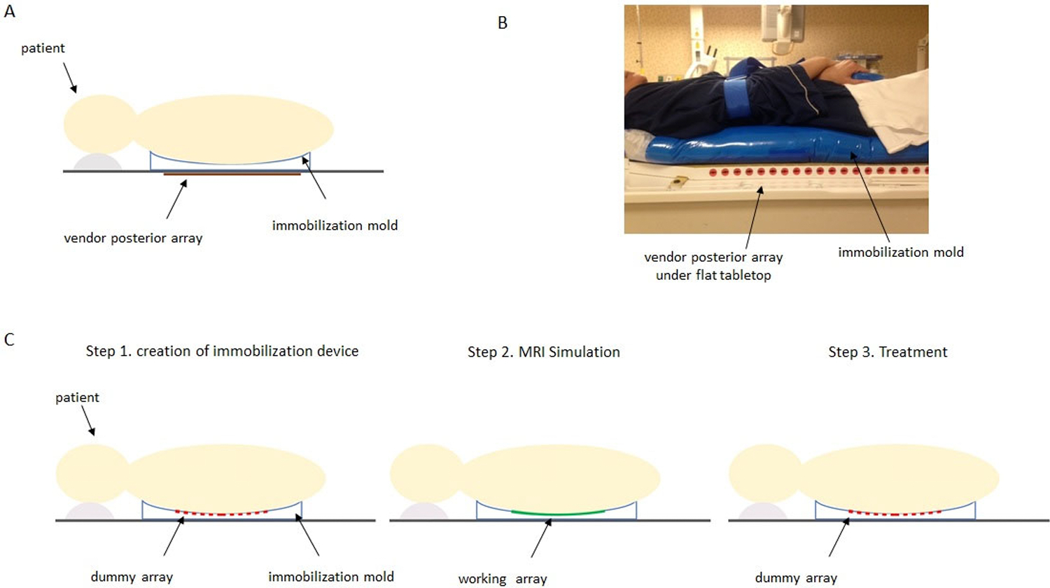
A) Diagram of subject set-up using the vendor’s in-table posterior array for imaging with the immobilization mold on the flat tabletop. B) Volunteer positioned in immobilization cradle on the flat MR tabletop for imaging with vendor array. The immobilization device consists of an Alpha Cradle (Smithers Medical Products, Inc., North Canton, OH, USA) and CDR frame (CDR Systems, Calgary, Alberta, CA). C) Proposed workflow using flexible array within immobilization mold. The immobilization device is made with the dummy version of the flexible array in place. In Step 2, MRI simulation is performed using the working flexible 32 channel array. Finally, in Step 3, the patient is treated with the dummy array in place.
The goal of this study is (a) to design a flexible custom MR spine coil that can be used in conjunction with the radiotherapy immobilization device for spine radiotherapy (b) to assess the image quality provided by the custom spine coil in comparison with the FDA approved, vendor provided posterior coil array when used for radiotherapy treatment planning
II. Methods and Materials
A. Flexible Receive Coil Design Concept for RT Workflow
A flexible custom-designed 32 channel receive-only spine coil array has been developed for a 3 Tesla Ingenia MR scanner (Philips Healthcare, Best, The Netherlands) in collaboration with MRCoils BV (Zaltbommel, The Netherlands). The custom coil array is flexible enough to be placed on top of the radiation therapy (RT) immobilization mold/cradle and conform to the patient’s shape. The workflow for incorporating this array is shown in Figure 1C. A unique step which we have developed in the RT workflow is to use a “dummy” version of the coil array when making the self-hardening immobilization mold and during treatment. This dummy array has the same dimensions and flexible element backing pieces as the working coil array, but is constructed from polycarbonate, contains no electronic elements and is radiation-transparent. It is placed under the patient when the mold is made so that the mold shape will accommodate the working array. During the MRI simulation, the working array is placed in the mold for imaging, and ultimately, during treatment, the dummy array will be placed in the mold so that patient simulation positioning is replicated.
B. Coil Array Specifications
The coil array was designed to encompass a sensitive volume of ≥ 30 cm in the SI dimension and ≥15 cm in the transverse dimension with a depth of penetration to include the thickness of a vertebra plus 2 cm (approximately 12 cm penetration depth at midline). The coil consists of 32 individual elements (Figure 2) with overall length of 42 cm and width of 26 cm.
Figure 2.
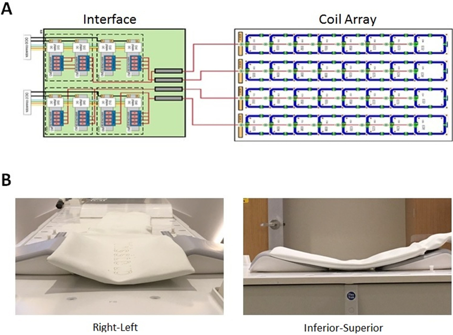
Schematic diagram of 32-channel custom spine array with interface to the scanner. B) photographs demonstrating flexibility of the array in right-left and inferior-superior dimensions.
The elements in the dimension along the magnet bore (vertical in the diagram) were overlapped to minimize mutual inductance. In the horizontal (right-left) dimension, a gap of 1.35 x width of the coil elements was employed for optimal SENSE [23] (parallel imaging) capability. To electrically detune the array during RF transmission, three capacitors on each array element are bypassed by parallel diodes. At each element’s feeding point, the coaxial cable is threaded and wound through a small vendor-designed printed-circuit board (PCB) to create an inductance. A capacitance was added to form a cable trap tuned to 127.8 MHz. The electrical isolation specified for each element was 15dB. Each coil element has a rigid backing which is flexibly linked to the backing of neighboring elements to permit molding of the coil to the shape of the patient. Four bundles containing 8 coaxial cables each are then passed through four additional ceramic cable traps manufactured by Philips and connected to low impedance preamplifiers in a custom-built interface box. Vendor proprietary hardware then interfaces the multichannel signals with the MRI system receiver hardware.
C. Custom array operation and phantom measurements
Initial testing on MR scanner utilized a 40 cm diameter cylindrical oil phantom (Figure S-2A). When the custom spine array is enabled, the vendor’s in-table posterior array is disengaged in software at the operator console. This causes the coil to be electronically detuned as well as physically moved within the table to a position where its elements do not overlap with those of the custom coil. Crosstalk between elements of the custom coil was measured by running an ultra-fast 3D gradient echo pulse sequence in the absence of RF and spatial encoding gradients and calculating a noise correlation matrix. Isolation of the custom coil from the permanent body coil was tested by mapping the body coil transmit B1 field while the custom coil was present and electronically detuned using an ultra-fast dual TR technique [24].
Signal-to-noise ratios were measured by running a two-dimensional sagittal multislice fast spin-echo pulse sequence (TR = 3000ms, TE = 120, echo train length = 24, 1 average, FOV = 420, slice thickness = 3, acquisition matrix = 504 x 384) and repeating the acquisition with the RF and gradient pulses turned off to generate a noise-only scan. A 40 cm diameter cylindrical phantom was placed on top of the custom array with approximately a 5 mm gap to avoid signal saturation directly adjacent to the array. For comparison, the phantom was raised 2.5 cm above the tabletop to simulate the effect of the immobilization mold on patient positioning and the imaging series was repeated. All scaling factors were made identical. To assess performance during SENSE acceleration, SNR measurements were performed with SENSE off and with SENSE acceleration factors of 2, 3, 4, 5, and 6. Noise values for all images were obtained by placing a large ROI in the real noise-only image and using the standard deviation of the ROI signal for the noise value. SNR values were calculated by dividing the signal magnitude in an ROI or along a profile line by the noise value. Coil array g factors were calculated using the formula:
where SNRfull is the SNR measured in the image where SENSE was not used, SNRSENSE is the SNR in the same ROI in an image obtained with SENSE, and R is the acceleration factor. Assuming perfect electrical isolation between array elements, the only source of decreased SNR during parallel imaging is the reduced number of phase-encode steps and the g factor should be 1. If the SNR is further decreased resulting in a g factor greater than one, the likely source is noise shared among array elements due to imperfect electrical isolation.
D. Normal Volunteer Imaging
Four normal volunteers of different body mass index (BMI) were scanned according to a protocol approved by our Institutional Review Board. MR images were acquired using the permanent body coil for transmission combined with 1) the custom 32-channel spine coil receive array and 2) the vendor provided 12-element posterior receive array. To simplify SNR comparisons, vendor’s anterior array was not employed. A custom spine immobilization mold was made for each volunteer by placing a plastic bag containing commercial polyurethane-foam material (Alpha Cradle, Smithers Medical Devices) on the flat table top, positioning the dummy array atop the mold, and then having the volunteer lie on top of the dummy array as the mold hardened. An example of the resulting immobilization device with the custom array in place is shown in Figure S-2b. Volunteer images were used to assess the extent of the field of view, SNR, acceleration capabilities, and presence of artifacts. Images included a T2-weighted two-dimensional multislice fast-spin-echo (FSE) axial series with SENSE acceleration [23], and a 3D T2-weighted sagittal tubo-spin-echo (TSE) series using either SENSE or CS-SENSE (Philips Healthcare, Best, The Netherlands), a proprietary algorithm which combines SENSE-based acceleration with sparse sampling and compressed sensing reconstruction [25]. Image acquisition details are shown in Table 1.
Table 1.
Pulse sequence parameters used in normal volunteer imaging. TSE: Turbo spin echo, CS: compressed sensing.
| Series Description | Voxel Size (mm3) matrix |
TE/TR (ms) | Acceleration Technique | Acceleration Factor | Averages | Scan Time |
|---|---|---|---|---|---|---|
| Axial T2 2D Multislice TSE | 0.9 x 0.9 x 3.0 316 x 232 x 42 |
95/4899 | SENSE | 2 (RL) | 2 | 2 min 56 s |
| Sagittal T2 3D TSE | 1.1 x 1.1 x 1.1 343 x 344 x 330 |
174/2700 | SENSE | 2 x 2 (RL, SI) |
1 | 9 min 54 s |
| Sagittal T2 3D TSE | 1.1 x 1.1 x 1.1 343 x 344 x 330 |
140/2700 | CS-SENSE | 7.3* | 1 | 4 min 49s |
Because CS-SENSE contains proprietary algorithms, information on the amount and type of acceleration in each dimension is unavailable.
III. Results
A. Phantom Results
The custom spine coil operated without malfunction and was compatible with parallel imaging acceleration. The noise correlation assessment showed at least 25dB isolation between all coil elements (See Figure 3a). The body coil transmit B1 field was not perturbed when the custom array was in place, indicating that the active decoupling circuitry in the custom array successfully prevented induction of currents by the body coil (Figure 3b–d).
Figure 3:
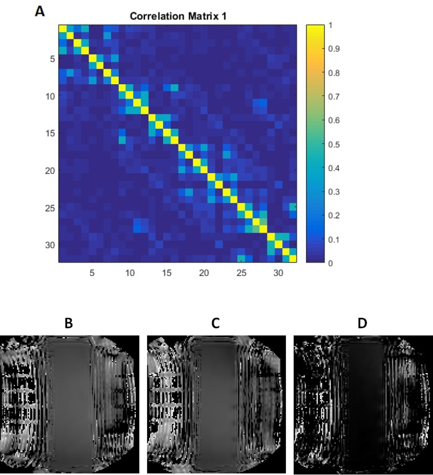
Custom array noise correlation matrix and body coil transmit maps. A) Noise correlation matrix for 32-channel array. The diagonal elements of the matrix quantify the total noise power of a given element while the off-diagonal elements describe the noise correlations between multiple elements. The noise correlation assessment showed at least 25dB isolation between all coil elements. For display purposes, values were normalized to a maximum value of 1.0. B) body coil transmit B1 field maps with no posterior array, C) body coil transmit map with 32 channel custom spine array in place and electronically detuned. D) difference between transmit maps B and C. The difference between transmit maps when the custom array was in place was negligible, indicating the absence of coupling between the body coil and the custom coil array.
Signal-to-noise ratio measurements obtained with the 40 cm cylinder phantom in “treatment position” are shown in Figure 4. Sagittal plane SNR maps (Figures 4A and 4B) were derived from signal and noise images. As seen in Figure 4C, the custom array demonstrated SNR which exceeded that of the vendor posterior array by a factor of 3.0 to 1.0 over the depth of the phantom (approximately 10 cm).
Figure 4.
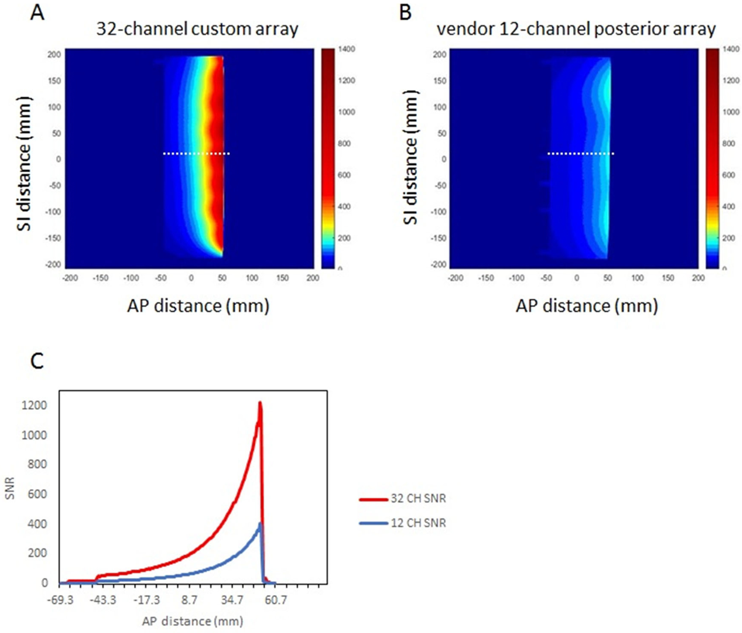
Signal-to-noise ratio (SNR) comparison between custom 32-channel spine array and vendor 12-channel posterior array. SNR maps are derived from sagittal 5 mm thick sections through a 4 cm diameter oil phantom. In each case, the phantom was positioned to reproduce the anterior-posterior patient-to-coil distance expected when the patient is lying in the immobilization mold. For the custom array, the phantom was placed 5 mm above the array. For the vendor array, the phantom was positioned 2.5 cm above the flat tabletop. A-B) SNR maps in the sagittal plane, C) signal-to-noise ratio profiles at the locations indicated by the dashed white lines
When the same fast spin-echo acquisition was repeated with increasing SENSE acceleration factors in the superior-inferior dimension, the vendor array began to demonstrate acceleration-related artifacts at SENSE factors greater than 3, due to the limited number of elements while the custom array did not show artifacts until acceleration was greater than 6. This is expected due to the larger number of coil elements in the SI dimension in the custom array. The g-factor results are shown in Table 2 indicating that both coils have acceptable noise losses when acceleration is used. For g-factor maps at SENSE factor = 2, see Figure S-3.
Table 2.
g factors calculated for multiple SENSE acceleration factors for the custom 32 channel array and the vendor posterior 12 channel array. SENSE acceleration was applied in the superior-inferior (SI) dimension. NA: the vendor array had 3 elements in the SI dimension; therefore SENSE = 4 was not tested.
| Acceleration factor | 32 Channel Flexible Array | Vendor 12 Channel Array |
|---|---|---|
| 0 | - | - |
| 2 | 1.00 | 1.01 |
| 3 | 1.05 | 1.06 |
| 4 | 0.97 | NA |
B. Volunteer Results
Four volunteers were scanned using the custom spine array. Two of the volunteers were scanned on multiple occasions so that the immobilization device positioning as well as the imaging parameters and acceleration factors could be optimized. Time on the table ranged from 30–90 minutes. In Figure 5, axial, two-dimensional multislice images obtained with both arrays using identical acquisition parameters are shown. While the spinal nerves were well-defined in both sets of images, the signal-to-noise ratio was clearly superior when the custom 32-channel array was used.
Figure 5.
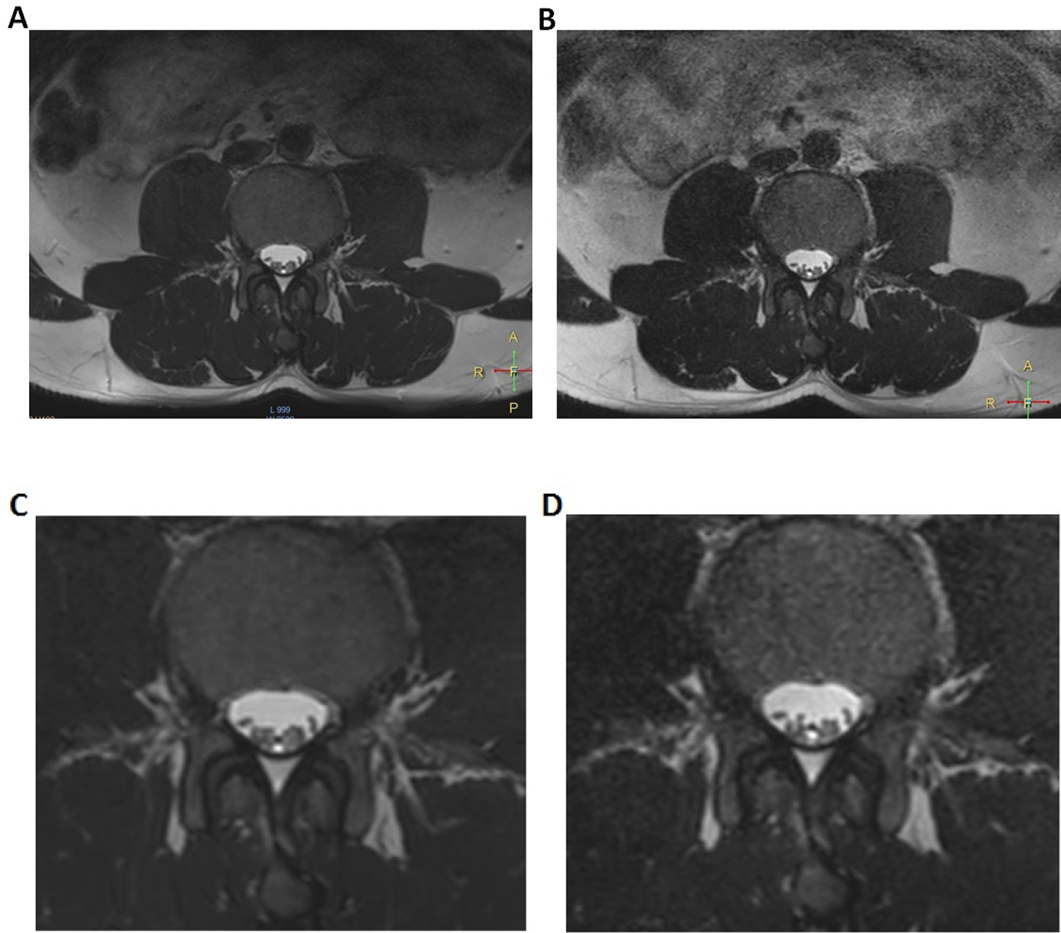
Axial T2-weighted multislice images obtained in a normal volunteer. Image A was obtained using the custom 32-channel array while image B is the nearest corresponding section obtained using the vendor’s posterior array. Images C and D are magnified subsections of A and B, respectively. Acquisition parameters are contained in Table 1.
To further test SNR and acceleration capabilities, three-dimensional isotropic data sets were obtained using SENSE acceleration in both RL and SI dimensions (Figure. 6). The usable superior-inferior field-of view for the custom spine array was approximately 28 cm encompassing 9 vertebrae in this subject. The improved SNR obtained with the 32-channel array within the immobilization device is evident. Further SENSE acceleration using the vendor posterior array resulted in artifacts. However, because SNR in the custom array images was more than adequate, an enhanced acceleration using a CS-SENSE factor of 7.3 was employed to scan the same matrix in 4 minutes 49 seconds (Figure S-4a).
Figure 6.
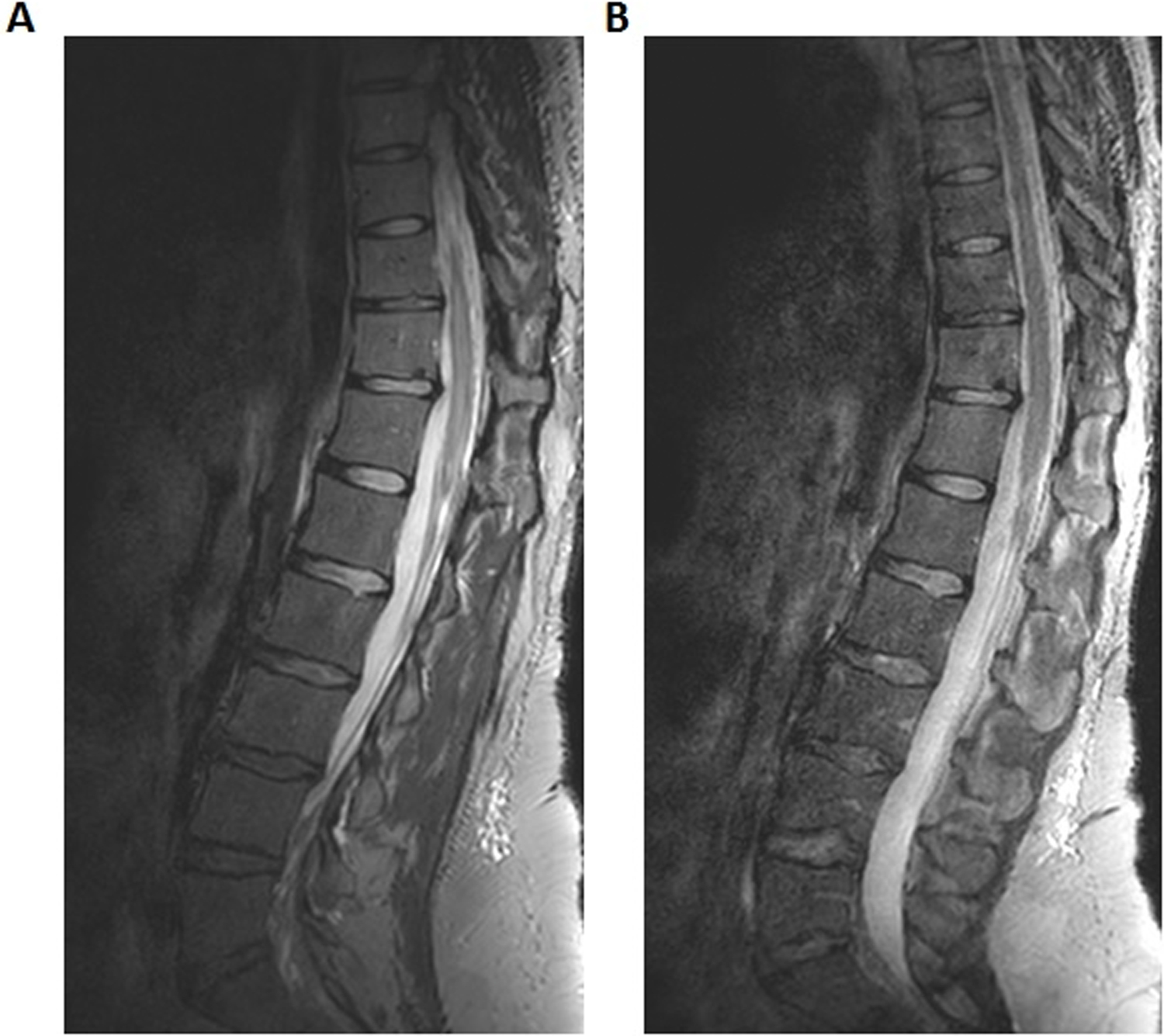
Three-dimensional sagittal images obtained using a 3D T2 Sagittal TSE pulse sequence with SENSE acceleration factors of 2 in RL and SI dimensions. A) Custom 32-channel array, B) Vendor posterior array. Voxel size was 1.1 x 1.1 x 1.1 mm3 and scan time was 9 minutes, 54 seconds. Full acquisition parameters are contained in Table 1.
The large number of elements and high SNR due to coil proximity to the subject enabled acquisition of a high quality, high-spatial-resolution three-dimensional image in a reasonable scan time. The same prescription could not be used successfully with the vendor array because of the lower number of coil elements (Figure S-4b). Figure 7 contains CS-SENSE 7.3 images reformatted in all three dimensions which could enable contouring of tissue volumes in multiple planes with equal resolution.
Figure 7.
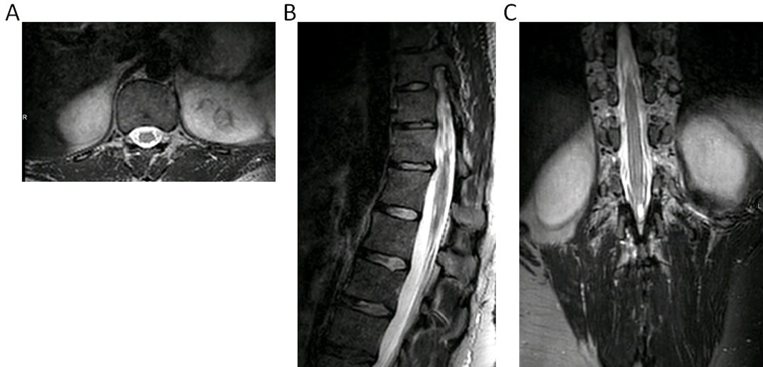
Planes extracted from a three-dimensional T2 Sagittal TSE data set obtained with the custom 32-channel array using compressed sensing combined with SENSE for a combined acceleration factor of 7.3. A) reformatted axial plane, B) sagittal plane, C) reformatted coronal plane. Voxel size was 1.1 x 1.1 x 1.1 mm3 and scan time was 4 minutes, 49 seconds for a 343 x 344 x 330 acquisition matrix. Full acquisition parameters are contained in Table 1.
Discussion
The current study assessed the feasibility of constructing a flexible 32-channel MR receiver array, incorporating it into the treatment immobilization device, and assessing its performance for spine imaging in anticipation of developing an MR-based spine SBRT workflow. The eventual goal is to compare CT myelogram-based spinal cord delineation with MR-based spinal cord delineation using custom-designed spine coil. Phantom experiments demonstrated that, as expected, the small distance between the custom coil array and the phantom generated highly superior SNR immediately adjacent to the custom array in addition to continued superiority over the vendor’s embedded posterior array to a depth greater than 10 cm. The noise correlation matrix and calculated g factors indicate that the array has noise performance comparable to the vendor array. In all four volunteers, a dummy coil was used to make a hardened foam immobilization cradle which could subsequently accommodate the working 32-channel array. Two-dimensional multislice and three-dimensional images demonstrated the excellent SNR of the flexible array as well as the acceleration advantage due to the high number of elements. The combination of SENSE-based acceleration and compressed SENSING permitted the acquisition of high resolution, isotropic imaging extending over 8 vertebrae in less than 5 minutes which will allow contouring of structures in multiple planes. While we were able to visualize nerve roots with excellent image quality, the ultimate test of the array will be in patients with tumors. The next step in our study will be to fully incorporate the custom array and the dummy array in a full treatment workflow in patients undergoing spine SBRT.
The particular needs of MRI receive coil design for radiation therapy are well-recognized and are beginning to be addressed [26–28]. The necessity for integration with treatment immobilization devices while maintaining high SNR accords well with flexible coil array designs. For example, application of the adaptive image receive or “AIR” coil design (GE Healthcare, Waukesha, WI) has been demonstrated in the head and neck imaging in treatment position [26]. These “flexible linked” resonator arrays permit bending of individual elements and changes in coil overlap while maintaining good element isolation and thus SNR. While not targeted specifically for RT applications, screen-printed flexible coil arrays also have the potential for use in treatment planning [29]. Two groups have reported fixed geometry coils tailored specifically for the spine. Zhao, et. al. built a 16-channel array on a fixed rigid mold which conformed to the shape of the neck and shoulders allowing close proximity of receiver to cervical spine [30]. Maus, et. al. developed an 8–12 channel array which could be wrapped around the dorsal region of a swine for image-guided targeting of epidural injections [31].
The flexible array does have some limitations. Individual elements are not as flexible as the GE AIR coil and the amount of overlap is fixed. However, because of the small individual size and large number of elements, the flexibility of the entire array was more than adequate for spine imaging while the rigidity of the elements provided structural support to be placed directly underneath the patient. This study was performed to demonstrate the feasibility and image quality advantage of incorporating a coil array within an immobilization device rather than using a standard, in-table posterior coil for spine imaging for RT treatment planning. We compared our array to the vendor posterior coil to provide a frame of reference with the expectation that the custom array with a higher number of elements and closer proximity to the subject would provide enhanced SNR and higher acceleration resulting in shorter acquisition time. This study does not suggest that the vendor coil is in any way inferior as a multipurpose diagnostic coil.
Conclusions
The 32-channel custom spine array present here provided high-quality images while keeping within the constraints of subject positioning in a radiation therapy immobilization mold, enabling seamless incorporation into the treatment planning workflow. In addition, the custom-designed form-fitting flexible spine coil array provided enhanced SNR and increased acceleration compared to the vendor’s posterior array. Future studies will compare MR-based spinal cord delineation using custom spine coil with the standard-of-care CT myelogram for spine radiotherapy planning.
Supplementary Material
Figure S-1: Typical CT myelogram showing spinal cord delineation for SBRT treatment planning. (a) CT myelogram is shown in the left image with contours shown in the right (magenta: spinal cord, blue/green: planning target volume contours). (b) A single fraction plan displayed in axial and sagittal planes showing the proximity of spinal cord to the prescription dose of 24 Gy. Both 24 Gy (green) and 14 Gy (blue) isodose lines are displayed.
Figure S-2. Custom 32-channel array experiment positions; A) beneath cylindrical phantom used for SNR measurements, B) in immobilization cradle.
Figure S-3. Geometry factor (g factor) maps obtained using the custom flexible array (A) and the vendor posterior array (B). SENSE acceleration factor = 2. Figures were obtained in the sagittal plane. White box indicates the cross section of the phantom. 1000 units corresponds to a g factor of 1. The maps were obtained using vendor proprietary software.
Figure S-4. Three dimensional sagittal T2-weighted TSE images obtained with combined SENSE and compressed sensing acceleration. A) custom 32-channel array, B) vendor posterior array. Voxel size was 1.1 x 1.1 x 1.1 mm3 and scan time was 4 minutes, 49 seconds for a 343 x 344 x 330 acquisition matrix. Full acquisition parameters are contained in Table 1.
Acknowledgements
The authors would like to acknowledge Dr. Lizet Dirks and Dr. Paul de Heer for their assistance in testing the coil. This research was partially supported by the NIH/NCI Cancer Center Support Grant/Core Grant (P30 CA008748).
Footnotes
Conflict of Interest
The authors have no conflicts to disclose.
References
- [1].Foote M, Letourneau D, Hyde et. al. Technique for stereotactic body radiotherapy for spinal metastases. Journal of clinical neuroscience : official journal of the Neurosurgical Society of Australasia 2011;18(2):276–279. [DOI] [PubMed] [Google Scholar]
- [2].Guckenberger M, Mantel F, Gerszten PC et al. Safety and efficacy of stereotactic body radiotherapy as primary treatment for vertebral metastases: a multi-institutional analysis. Radiation oncology 2014;9:226. [DOI] [PMC free article] [PubMed] [Google Scholar]
- [3].De Bari B, Alongi F, Mortellaro G et al. Spinal metastases: Is stereotactic body radiation therapy supported by evidences? Crit Rev Oncol Hematol 2016;98:147–158. [DOI] [PubMed] [Google Scholar]
- [4].Husain ZA, Thibault I, Letourneau D et al. Stereotactic body radiotherapy: a new paradigm in the management of spinal metastases. CNS Oncol 2013;2(3):259–270. [DOI] [PMC free article] [PubMed] [Google Scholar]
- [5].Lo SS, Chang EL, Ryu S et al. Best of International Stereotactic Radiosurgery Society Congress 2013: stereotactic body radiation therapy. Part I: spinal tumors. Future Oncol 2013;9(9):1299–1302. [DOI] [PubMed] [Google Scholar]
- [6].Lo SS, Sahgal A, Wang JZ et al. Stereotactic body radiation therapy for spinal metastases. Discov Med 2010;9(47):289–296. [PubMed] [Google Scholar]
- [7].Sahgal A, Bilsky M, Chang EL et al. Stereotactic body radiotherapy for spinal metastases: current status, with a focus on its application in the postoperative patient. J Neurosurg Spine 2011;14(2):151–166. [DOI] [PubMed] [Google Scholar]
- [8].Sahgal A, Ma L, Weinberg V et al. Reirradiation human spinal cord tolerance for stereotactic body radiotherapy. Int J Radiat Oncol Biol Phys 2012;82(1):107–116. [DOI] [PubMed] [Google Scholar]
- [9].Choi CY, Adler JR, Gibbs ICet. al. Stereotactic radiosurgery for treatment of spinal metastases recurring in close proximity to previously irradiated spinal cord. Int J Radiat Oncol Biol Phys 2010;78(2):499–506. [DOI] [PubMed] [Google Scholar]
- [10].Sahgal A, Weinberg V, Ma L et al. Probabilities of radiation myelopathy specific to stereotactic body radiation therapy to guide safe practice. Int J Radiat Oncol Biol Phys 2013;85(2):341–347. [DOI] [PubMed] [Google Scholar]
- [11].Al-Omair A, Smith R, Kiehl TR et al. Radiation-induced vertebral compression fracture following spine stereotactic radiosurgery: clinicopathological correlation. J Neurosurg Spine 2013;18(5):430–435. [DOI] [PubMed] [Google Scholar]
- [12].Sahgal A, Whyne CM, Ma L, Larson DA, Fehlings MG. Vertebral compression fracture after stereotactic body radiotherapy for spinal metastases. Lancet Oncol 2013;14(8):e310–320. [DOI] [PubMed] [Google Scholar]
- [13].Thariat J, Castelli J, Chanalet S et al. CyberKnife stereotactic radiotherapy for spinal tumors: value of computed tomographic myelography in spinal cord delineation. Neurosurgery 2009;64(2 Suppl):A60–66. [DOI] [PubMed] [Google Scholar]
- [14].Sandow BA, Donnal JF. Myelography complications and current practice patterns. AJR Am J Roentgenol 2005;185(3):768–771. [DOI] [PubMed] [Google Scholar]
- [15].Maly P, Sundgren P, Baath L, Golman K, Walday P. Adverse reactions in myelography. Acta Radiol Suppl 1995;399:230–237. [PubMed] [Google Scholar]
- [16].Bohn HP, Reich L, Suljaga-Petchel K. Inadvertent intrathecal use of ionic contrast media for myelography. AJNR Am J Neuroradiol 1992;13(6):1515–1519. [PMC free article] [PubMed] [Google Scholar]
- [17].Husband DJ, Grant KA, Romaniuk CS. MRI in the diagnosis and treatment of suspected malignant spinal cord compression. Br J Radiol 2001;74(877):15–23. [DOI] [PubMed] [Google Scholar]
- [18].Li KC, Poon PY. Sensitivity and specificity of MRI in detecting malignant spinal cord compression and in distinguishing malignant from benign compression fractures of vertebrae. Magn Reson Imaging 1988;6(5):547–556. [DOI] [PubMed] [Google Scholar]
- [19].Loughrey GJ, Collins CD, Todd SM, Brown NM, Johnson RJ. Magnetic resonance imaging in the management of suspected spinal canal disease in patients with known malignancy. Clin Radiol 2000;55(11):849–855. [DOI] [PubMed] [Google Scholar]
- [20].Toussaint A, Richter A, Mantel F et al. Variability in spine radiosurgery treatment planning - results of an international multi-institutional study. Radiation oncology 2016;11:57. [DOI] [PMC free article] [PubMed] [Google Scholar]
- [21].Hanvey S, McJury M, Tho LM et al. The influence of MRI scan position on patients with oropharyngeal cancer undergoing radical radiotherapy. Radiation oncology 2013;8:129. [DOI] [PMC free article] [PubMed] [Google Scholar]
- [22].Hayes CE, Axel L. Noise performance of surface coils for magnetic resonance imaging at 1.5 T. Med Phys 1985;12(5):604–607. [DOI] [PubMed] [Google Scholar]
- [23].Pruessmann KP, Weiger M, Scheidegger MB, Boesiger P. SENSE: sensitivity encoding for fast MRI. Magn Reson Med 1999;42(5):952–962. [PubMed] [Google Scholar]
- [24].Yarnykh VL. Actual flip-angle imaging in the pulsed steady state: a method for rapid three-dimensional mapping of the transmitted radiofrequency field. Magn Reson Med 2007;57(1):192–200. [DOI] [PubMed] [Google Scholar]
- [25].Lustig M, Donoho D, Pauly JM. Sparse MRI: The application of compressed sensing for rapid MR imaging. Magn Reson Med 2007;58(6):1182–1195. [DOI] [PubMed] [Google Scholar]
- [26].McGee KP, Stormont RS, Lindsay SA et al. Characterization and evaluation of a flexible MRI receive coil array for radiation therapy MR treatment planning using highly decoupled RF circuits. Phys Med Biol 2018;63(8):08NT02. [DOI] [PubMed] [Google Scholar]
- [27].Paulson ES, Erickson B, Schultz C, Allen Li X. Comprehensive MRI simulation methodology using a dedicated MRI scanner in radiation oncology for external beam radiation treatment planning. Med Phys 2015;42(1):28–39. [DOI] [PubMed] [Google Scholar]
- [28].Wong OL, Yuan J, Yu SK, Cheung KY. Image quality assessment of a 1.5T dedicated magnetic resonance-simulator for radiotherapy with a flexible radio frequency coil setting using the standard American College of Radiology magnetic resonance imaging phantom test. Quant Imaging Med Surg 2017;7(2):205–214. [DOI] [PMC free article] [PubMed] [Google Scholar]
- [29].Corea JR, Flynn AM, Lechene B et al. Screen-printed flexible MRI receive coils. Nature communications 2016;7:10839. [DOI] [PMC free article] [PubMed] [Google Scholar]
- [30].Zhao W, Cohen-Adad J, Polimeni JR et al. Nineteen-channel receive array and four-channel transmit array coil for cervical spinal cord imaging at 7T. Magn Reson Med 2014;72(1):291–300. [DOI] [PMC free article] [PubMed] [Google Scholar]
- [31].Maus TP, Felmlee JP, Unger MD, Beutler AS. MRI guidance technology development in a large animal model for hyperlocal analgesics delivery to the epidural space and dorsal root ganglion. J Neurosci Methods 2019;312:182–186. [DOI] [PMC free article] [PubMed] [Google Scholar]
Associated Data
This section collects any data citations, data availability statements, or supplementary materials included in this article.
Supplementary Materials
Figure S-1: Typical CT myelogram showing spinal cord delineation for SBRT treatment planning. (a) CT myelogram is shown in the left image with contours shown in the right (magenta: spinal cord, blue/green: planning target volume contours). (b) A single fraction plan displayed in axial and sagittal planes showing the proximity of spinal cord to the prescription dose of 24 Gy. Both 24 Gy (green) and 14 Gy (blue) isodose lines are displayed.
Figure S-2. Custom 32-channel array experiment positions; A) beneath cylindrical phantom used for SNR measurements, B) in immobilization cradle.
Figure S-3. Geometry factor (g factor) maps obtained using the custom flexible array (A) and the vendor posterior array (B). SENSE acceleration factor = 2. Figures were obtained in the sagittal plane. White box indicates the cross section of the phantom. 1000 units corresponds to a g factor of 1. The maps were obtained using vendor proprietary software.
Figure S-4. Three dimensional sagittal T2-weighted TSE images obtained with combined SENSE and compressed sensing acceleration. A) custom 32-channel array, B) vendor posterior array. Voxel size was 1.1 x 1.1 x 1.1 mm3 and scan time was 4 minutes, 49 seconds for a 343 x 344 x 330 acquisition matrix. Full acquisition parameters are contained in Table 1.


