Abstract
Background:
TMS neuronavigation with on-line display of the induced electric field (E-field) has the potential to improve quantitative targeting and dosing of stimulation, but present commercially available solutions are limited by simplified approximations.
Objective:
Developing a near real-time method for accurate approximation of TMS induced E-fields with subject-specific high-resolution surface-based head models that can be utilized for TMS navigation.
Methods:
Magnetic dipoles are placed on a closed surface enclosing an MRI-based head model of the subject to define a set of basis functions for the incident and total E-fields that define the subject’s Magnetic Stimulation Profile (MSP). The near real-time speed is achieved by recognizing that the total E-field of the coil only depends on the incident E-field and the conductivity boundary geometry. The total E-field for any coil position can be obtained by matching the incident field of the stationary dipole basis set with the incident E-field of the moving coil and applying the same basis coefficients to the total E-field basis functions.
Results:
Comparison of the MSP-based approximation with an established TMS solver shows great agreement in the E-field amplitude (relative maximum error around 5%) and the spatial distribution patterns (correlation > 98%). Computation of the E-field took ~100 ms on a cortical surface mesh with 120k facets.
Conclusion:
The numerical accuracy and speed of the MSP approximation method make it well suited for a wide range of computational tasks including interactive planning, targeting, dosing, and visualization of the intracranial E-fields for near real-time guidance of coil positioning.
Keywords: Transcranial magnetic stimulation, Dipole basis functions, Magnetic stimulation profile, Targeting, Dosing, Neuronavigation
1. Introduction
Transcranial magnetic stimulation (TMS) (Barker et al., 1985) has an important role in research of the healthy human brain. It is also FDA approved for treating depression (O’Reardon et al., 2007), obsessive-compulsive disorder (Carmi et al., 2019), migraine (Lipton et al., 2010), and presurgical localization of eloquent cortex (Picht et al., 2011), with more clinical applications under investigation. TMS employs time-varying magnetic fields (B-fields) to induce electric fields (E-fields) according to Maxwell-Faraday law, enabling painless and safe stimulation of electrically excitable tissue even at suprathreshold intensities (see, e.g., (Rossi et al., 2009)). While the B-field passes through the biological tissue essentially undisturbed, the E-field is influenced by tissue conductivity boundaries where a conservation condition holds for the TMS-induced currents in the pulse frequency range of interest (< 10 kHz). The intracranial total E-field distribution is therefore the sum of the incident E-field of the coil in free space and the secondary E-field determined by the tissue conductivity boundaries (Roth et al., 1990). The total E-field determines which areas are stimulated and which are not. Therefore, E-field modeling can be leveraged in neuronavigation where the electric field is visualized in the context of brain anatomy to facilitate coil positioning (see, e.g., (Ruohonen and Karhu, 2010)) for optimal effects of TMS. Furthermore, the E-field estimates can be utilized to normalize the dosing of the TMS such that the intended intensity at the target region is reached. The potential to improve quantitative targeting and dosing of TMS makes the E-field modeling a powerful tool for both research and clinical applications.
Several methods have been proposed to compute spatial distribution and intensity of TMS-induced E-fields. Spherically symmetric models approximate the head either using a globally or locally fitted sphere to approximate the shape of the skull (see, e.g., (Nummenmaa et al., 2013; Thielscher and Kammer, 2002)). While the spherical models are useful and computationally efficient due to availability of an analytical solution for the E-field, such models are not capable of capturing the full geometric complexities of individual skull shapes or intracranial tissue compartments including cerebrospinal fluid (CSF) or cortical gray/white matter boundaries (Chen and Mogul, 2009; Thielscher et al., 2011). To enable anatomically realistic modeling, several approaches have been proposed that employ volumetric meshing-based techniques such as the Finite Element Method (FEM) (Windhoff et al., 2013). More recently, a surface-based Boundary Element Method (BEM) utilizing Fast Multilevel Multipole (FMM) was proposed (Makarov et al., 2018) to enable handling high-resolution models. This approach has a favorable scaling of computational cost in comparison with FEM techniques when the level of geometrical detail is increased (Gomez et al., 2020; Htet et al., 2019). Despite the improvements in both BEM-FMM (Makarov et al., 2020) and FEM (Saturnino et al., 2019a), neither approach is directly applicable to the neuronavigation where the coil position is updated and the E-fields are visualized several times per second.
To the best of our knowledge, all currently available commercial neuronavigation systems employ spherical models. Recently, a BEM approach was presented to calculate the E-fields on a ‘medium-resolution’ model utilizing a Graphics Processing Unit (GPU) to maximize the speed of the computations (Stenroos and Koponen, 2019). For such approach, as FMM acceleration was not utilized, the scalability to full high-resolution models remains a challenge due to the memory constraints imposed by the GPU acceleration. Additionally, a deep learning-based approach was presented to retrieve the E-fields with a speed that is suitable for neuronavigation applications (Yokota et al., 2019). While highly innovative and promising, large MRI datasets are required for training of the deep neural network to avoid overfitting. Therefore, the generalizability of this approach across different TMS coil types, MRI acquisition strategies with variable image quality, as well as natural variability in the brain geometry across subject populations remains open.
Here, we present a novel general approach for fast approximation of the TMS-induced electric fields for high-resolution subject-specific models. We should emphasize at the outset that the method for evaluating TMS-induced E-fields can be freely chosen: The novel aspect of our work is in how to rapidly and efficiently approximate the E-fields of an arbitrary TMS coil by using a pre-computed basis set. With its superior computational efficiency, the BEM-FMM is ideally suited for this purpose as the problem is formulated in terms of the tissue conductivity boundary surfaces, enabling a large set of solutions to be pre-calculated and stored. Therefore, we employ the BEM-FMM method but obtain a significant speed gain by pre-calculating and storing of the E-field solutions and by taking into account the fundamental physical principles of the underlying problem.
Our method is based on approximating the E-fields of a moving coil with the fields from a stationary basis set. Similar to Huygens principle (Baker and Copson, 2003), the basis set is assumed to consist of magnetic dipoles residing on a fictitious surface surrounding the subject’s head, but the approach can be readily generalized to arbitrary basis functions and/or three-dimensional grids. The Huygens principle itself and the related methodology of using surface currents to model TMS coils is well known (Koponen et al., 2015; Roth et al., 1994). However, to the best of our knowledge the framework presented here to utilize a ‘global’ dipole basis set to rapidly and accurately approximate the E-fields of an arbitrary, moving TMS coil within a general volume conductor is novel. The key physical insight enabling fast on-line calculation is that the total E-field is determined by the incident field of the TMS coil and the tissue conductivity boundaries. Hence, if the dipole basis set can be used to ‘match’ the incident field of the TMS coil, the total E-fields of the same combination of dipoles will also match due to the principle of linear superposition. Consequently, in neuronavigation applications where the coil is rapidly moved, we only need to estimate the incident E-field of the coil and the best matching combination of the incident E-fields of the dipoles, and the same weights of the dipoles can be applied to the pre-calculated basis set to retrieve the total E-field. Moreover, since the dipole basis set is independent of the used TMS coil and can be utilized to characterize the field in any magnetic stimulation scenario, we call this fundamental solution set the ‘Magnetic Stimulation Profile’ (MSP) of the subject. The article is organized as follows: First, we present a theoretical account and implementation of the method illustrated by example cases. Then, we provide quantitative accuracy metrics across multiple subjects by using the full BEM-FMM solution as the ground truth. Finally, we present computational benchmarking results and conclude the article with a discussion on the presented method and its potential applications and possible further improvements.
2. Methods
2.1. Computational modeling of the E-fields
The head models employed in this study consist of the following conductivity boundaries: Skin/scalp, skull, cerebro-spinal fluid (CSF), grey matter (GM) amd white matter (WM) obtained from anatomical MRI data by SimNIBS software (Saturnino et al., 2019b; Thielscher et al., 2015). The conductivity is assumed to be homogeneous within each tissue compartment defined by the boundary surfaces. As pre-existing freely available MRI data was used for all the simulations, no IRB-approved human subject study protocol was required. Since the BEM-FMM algorithm is described in previous publications (Htet et al., 2019; Makarov et al., 2020, 2018), here we only give a brief synopsis of the approach.
The TMS-induced E-field is determined by the Maxwell–Faraday law of induction ∇ × E = −∂𝑩/∂t from which it follows that the total E-field has the general form E = −∂A/∂t − ∇ϕ. For biological tissue with relatively low conductivities, the first term involving the vector potential Einc = −∂A/∂t corresponds to the primary field (excitation) induced by the current in the coil, whereas the term involving the scalar potential Es = −∇ϕ is called the secondary field. The primary and secondary fields are coupled through the condition of volumetric quasi-neutrality ∇ ⋅ J = ∇ ⋅ (σE) = 0 and the secondary field is hence generated by charge accumulation at the conductivity boundaries to render the normal component of the current continuous (see, e.g., (Miranda et al., 2007)).
The BEM-FMM method operates directly with electric charges associated with the scalar potential ϕ. We discretize the total combined surface S of all conductivity boundaries into N small planar triangles ti, i = 1, …, N with centers ci, i = 1, …, N, outer normal vectors of every manifold tissue shell ni, i = 1, …, N, and triangle areas Ai, i = 1, …, N. The unknown surface charge density is constant for every triangle and equal to 𝜌i, i = 1, …, N. Purely parametric time dependence is eliminated via separation of variables. The formulation results in a system of linear equations for unknown induced charges at the boundaries that is solved iteratively. For the nth iteration:
| (1) |
| (2) |
where Einc and Es are the incident field of the coil and secondary field of charges induced at the interface of any two compartments with conductivities σin and σout, respectively, and ε0 is the permittivity of vacuum. The major burden of the iterative solution is the repeated computation of the electric field from a large ensemble of point charge sources at a large number of target points following Eq. (2). This is exactly the objective of FMM that enables rapid evaluation of the sums and massive acceleration for high-resolution head models.
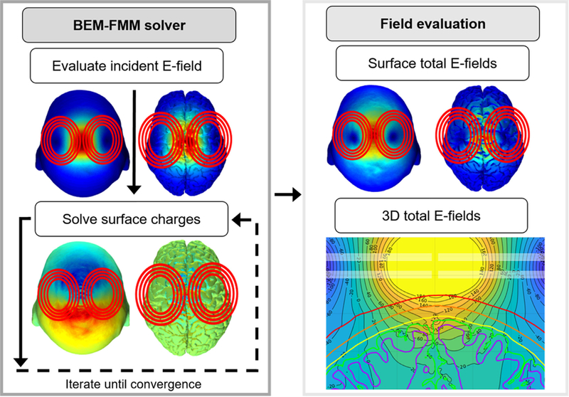
In practice, the equations are iteratively solved by the Generalized Minimal Residual Method (GMRES) (Saad and Schultz, 1986) and once the solution converges, the total E-field at any desired location of the space can be readily computed. The BEM-FMM approach is illustrated in Fig. 1. Computations were performed using MATLAB v 2019a (The MathWorks, Natick, MA) on an Intel Xeon E5–2360 with 128 GB of memory or with an Intel Xeon(R) Gold 6226R with 192 GB of memory.
Fig. 1.
The BEM-FMM approach. The incident E-field of the TMS coil is used to solve the surface boundary charges to satisfy the boundary conditions. The total E-field is then obtained as the sum of the incident E-field and the secondary E-field created by the surface charge density residing at the conductivity boundaries.
2.2. Matching the incident field of a moving coil with a set of stationary dipoles
Even with this optimized current version of the BEM-FMM approach, evaluation of the fields took 10 – 20 seconds (Makarov et al., 2020), leading to that the computational engine would not be able to keep up with the data stream from a neuronavigation system that typically employs frame rates between 5 −15 Hz. Here, we present a novel solution to overcome this limitation by utilizing a set of stationary dipole basis functions to rapidly approximate the fields of a moving TMS coil.
Physical motivation behind our approach is similar to the Huygens principle Baker and Copson, 2003): by using a basis set to approximate arbitrary surface current distributions, we can match the incident field of the moving coil with a weighted sum of the incident fields of stationary sources. The second key insight is based on the mathematics of the boundary value problem. If two coils produce identical incident fields, the total E-fields will also be identical as the solution is determined by the incident field and the tissue conductivity boundaries (see, Equations (1 & (2)). By linear superposition, this extends readily to the case of the dipole basis set.
For practical purposes, the dipole basis set can be selected such that it produces a flexible way to approximate the incident field of TMS coils. Here, instead of using surface currents we employ three Cartesian magnetic dipoles at each vertex of a discretized surface to increase degrees of freedom in the basis set as the incident E-field patterns of orthogonal dipoles will also be orthogonal. The incident fields of the dipole basis vector with unit amplitude are computed for desired locations and assembled into a matrix , where each column corresponds to the incident field from a dipole computed at the conductivity boundary surfaces. Then, for arbitrary dipole amplitudes m the incident field at any conductivity boundary surface of interest is given by:
| (3) |
where Ainc is a sub-matrix of corresponding to the surface of interest.
Now, given an incident field pattern Einc that is a vector defined at each location of the surface of interest or ‘matching region’, we can find optimal basis coefficients as the regularized minimum-norm solution:
| (4) |
and
| (5) |
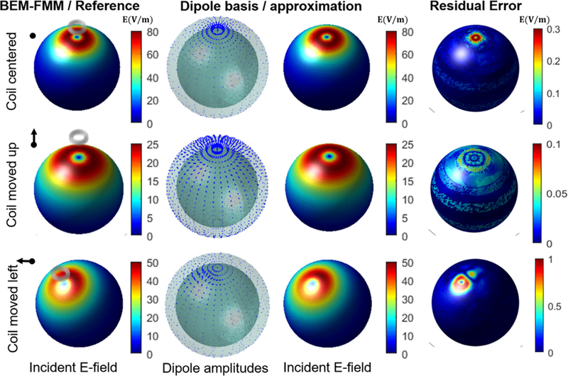
The regularization parameter λ was set to the 1000th highest singular value in the matrix (approximately 30% of the total number of dipole basis functions) for both sphere and anatomically realistic head models used in this study. To illustrate the capabilities of the dipole basis approximation, we compared the incident E-fields computed on a spherical surface for the dipole basis set and a circular TMS coil as shown in Fig. 2.
Fig. 2.
The incident E-field of a circular TMS coil on a spherical surface calculated by the BEM-FMM and the corresponding dipole approximation. Each row shows the results as the position of the coil changes. The amplitude of the dipole basis set changes according to the coil position in the expected fashion. The residual error shows the difference in the E-field amplitude between the full BEM-FMM and the dipole approximation. Note the different scales in the error bars of the residual plots.
As illustrated in Fig. 2, the amplitude and orientation distribution of the dipole basis changes when the coil is moved vertically or horizontally. The dipole basis set produces a highly accurate approximation of the incident E-field of the TMS coil with maximum residual error between 0.37%−2% among various coil positions. The computation here was done to illustrate the matching of the incident field of the TMS coil with the dipole basis. However, as described later in Eq. (6), by applying exactly the same linear combination of the dipoles for the total E-field basis functions results in an approximation of the corresponding total field.
2.3. Grid interpolation for fast evaluation of the incident field of a TMS coil
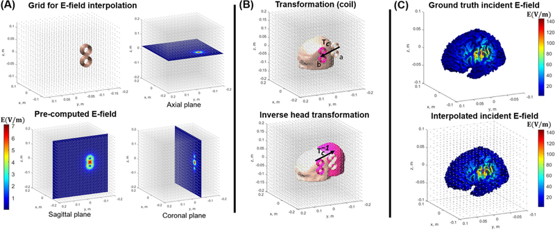
The incident E-field must be re-calculated every time the TMS coil position is changed. Although the calculation of incident E-field using the FMM approach is already quite fast (<1 s) (Htet et al., 2019; Makarov et al., 2020) we need to further speed up the process to reach near real-time performance. To this end, we propose an approach utilizing pre-calculation, interpolation, and spatial invariance of the incident E-field. It follows from the basic formula for the vector potential of a current element (see, e.g., (Makarov et al., 2018)) that the E-field of a TMS coil is translationally (and rotationally) invariant in free space and consequently moving the TMS coil along a certain direction is equivalent to moving the subject’s head in the opposite direction. This observation can be utilized in calculating a high-resolution map of the incident field of a TMS coil once, creating an interpolating function and storing the results. Subsequently, the incident field at the conductivity boundaries can be obtained by applying the process as follows. We position the TMS coil inside a dense 3D spatial grid as illustrated in Fig. 3 (A). The incident E-field of the coil is calculated on all the grid points and an interpolating function is created. Here, the MATLAB function “griddedInterpolant” was used to define the that utilizes a trilinear interpolation based on the incident E-field values at eight corners of each sub-cube within the full grid. Now as the coil moves from location “a” to “b” with the matrix Tc as shown in Fig. 3 (B), we transform the head surface model using and obtain the incident E-field at any conductivity boundary by using . The Tc is a rigid transformation matrix of the form , where Rc is the 3D rotation matrix and T0 is the translation vector from point “a” to “b”. The comparison between the interpolated and numerically exact results in Fig. 3 (C) shows that this approach indeed produces a highly accurate approximation.
Fig. 3.
(A) The grid interpolation approach for fast valuation of the incident E-field. We employ a cubic grid with 9 million points as the interpolation is extremely fast. The E-field magnitude is shown at different cross-sectional planes. (B) Moving the coil from point a to point b (top row, transformation matrix Tc) is equivalent of the subject’s head moving in the opposite direction (bottom row, transformation matrix Tc−1). (C) The resulting E-field from interpolation approach is shown on the WM surface (bottom row) along with the full BEM-FMM ground truth result (top row).
2.4. Linking the incident and total E-fields: The magnetic stimulation profile
To enable the rapid approximation scheme, we need to calculate the total E-fields of the dipole basis functions by using the BEM-FMM approach (up to 3000 dipole basis functions in this study). This is the most time-consuming part as obtaining one dipole solution takes ~ 20 seconds. However, this operation needs to be done only once per subject and, importantly, is independent of the TMS coil geometry. As illustrated in the Results section, this enables us to approximate any TMS coil and is therefore inherent to the subject’s anatomy (assuming a sufficient basis set is used). Due to this property, we call this fundamental solution the MSP of the subject. After calculating the total E-fields of the dipole basis set and assembling them in a matrix , we may obtain the approximate total E-field by one interpolation step and two simple matrix operations. Assuming that we have obtained an Einc of the TMS coil through the interpolation process described above, we estimate the dipole coefficients by , where W is given by equation (4). Then, the approximate total E-field is simply given by:
| (6) |
where Atot is again a sub-matrix of corresponding to a surface of interest.
This “linearized” approach eliminates the need for any iterative solver to be applied after the MSP of the subject has been calculated and allows for near real-time visualization of the total E-field of the moving TMS coil on the subject’s head model. The approach also decouples the TMS coil model and the MSP, enabling both to be independently pre-calculated, stored and subsequently linked through incident fields.
2.5. Near real-time E-field calculation pipeline
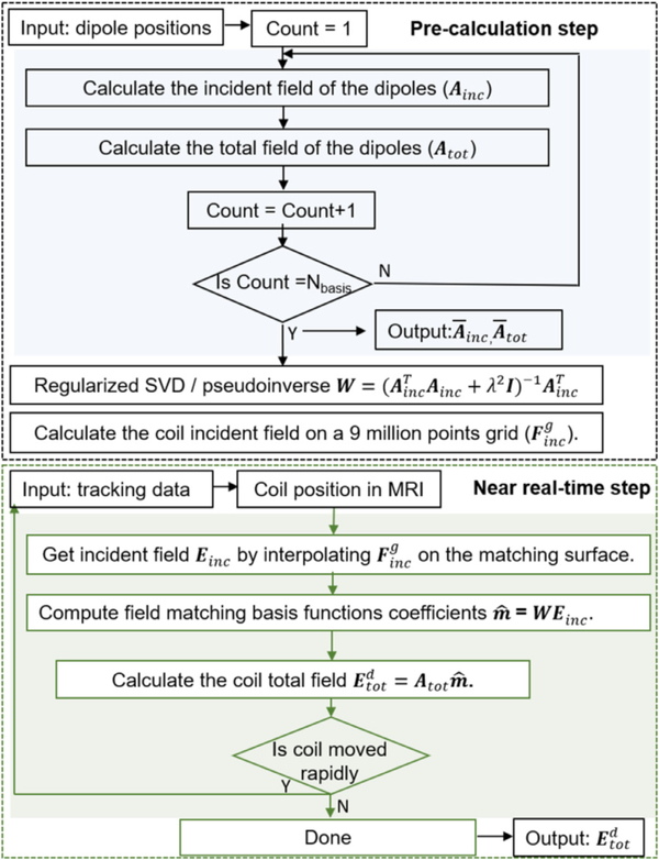
Near real-time visualization of the induced E-field requires a frame rate of 5 – 15 Hz, meaning every time the coil moves the total E-field must be calculated within 70 – 200 ms. This can be readily attained by the MSP-based approach. Fig. 4 shows the full E-field calculation pipeline which consists of a pre-calculation block and the near real-time block. The first step in the pre-calculation pipeline is performed to obtain the Ainc with Nd dipole basis functions (MSP step). The remaining pre-calculation steps are to compute the pseudo-inverse of the dipole basis set (W) according to equation (4) and finally to calculate the incident E-field of any desired TMS coil on a 3D cubic grid of Nc points using the FMM-based coil modeling approach (Htet et al., 2019; Makarov et al., 2018). In the near real-time step, first the incident E-field of the coil placed at an arbitrary location is calculated by interpolating the grid E-field on a desired brain surface (e.g., WM or GM). In the subsequent step, we compute the matching coefficients of dipole basis set using equation (5). Finally, the total E-field of the coil is obtained by equation (6). These steps are repeated when coil position changes and since the total computation time of these steps is around 100 ms a near real-time visualization of the total E-field was achieved by the proposed method.
Fig. 4.
Computational flowchart of the MSP dipole approximation for near real-time E-field calculation and navigation.
2.6. Quantitative accuracy metrics
To compare the accuracy of the MSP approach with the ground truth BEM-FMM solutions (Makarov et al., 2018) we use Correlation Coefficient (CC), Relative Error (RE), and Relative Maximum Error (RME) as the metrics (Stenroos and Koponen, 2019). Assuming Eref is the ground truth total E-field on a surface calculated by running the BEM-FMM until convergence (the GMRES solution converged to a residual of 0.00001 in 20 iterations (Makarov et al., 2020)) and EM is the total E-field computed by MSP dipole approximation, the accuracy metrics are defined as below:
| (7) |
| (8) |
| (9) |
In equation (9) for RME, represents the N highest values of Eref and this metric is used to estimate how accurately the peak E-field amplitudes are estimated (in this study, we used N = 10).The CC metric quantifies the similarity in the shape of the E-field distribution methods and is invariant with respect to a global scaling. The RE and RME metrics also take into account the differences both in the global and local values of the E-field amplitudes. The rationale of using such accuracy metrics is to quantify how well the E-fields calculated by MSP approach resemble the corresponding ground truth BEM-FMM solutions across different subjects and brain targets. However, we also provide several detailed visual comparisons to qualitatively assess the accuracy of the MSP approximation.
3. Results
3.1. Using the dipole basis MSP for general-purpose TMS approximation
As discussed in the Methods section, the subject-specific MSP can be used to approximate the E-field from any TMS coil positioned at an arbitrary location in space. To illustrate the capability of the MSP to approximate different coil types we used models of two commercially available TMS coils (MagVenture Cool-B35 and Cool D-B80). The Cool-B35 is a highly focal small-diameter coil whereas the Cool D-B80 offers high depth penetration so in this sense they represent extreme cases that one might encounter for practical studies (Cortes et al., 2013; Ishkhanyan et al., 2020; Kreuzer et al., 2019; Pavon et al., 2019).
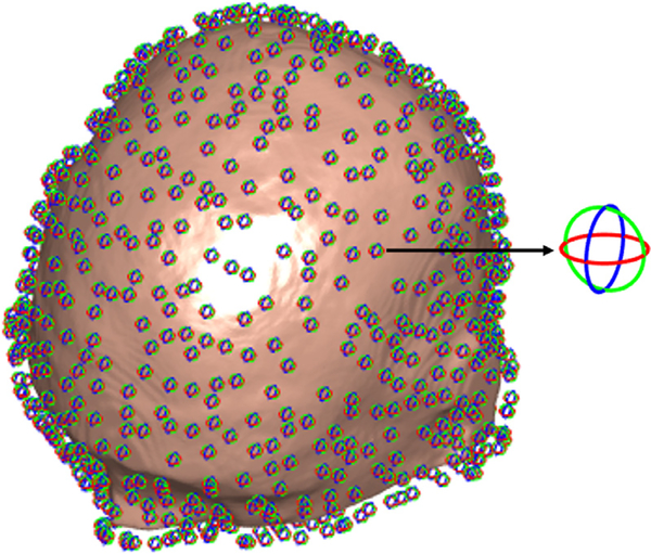
We calculated the incident and total E-fields of the coils using the BEM-FMM solution as a ground truth and compared the consistency with the MSP dipole basis approximation visually. We placed 3000 dipole basis functions (1000 locations with three orthogonal dipoles each) uniformly at 2 mm distance from the skin surface as shown in Fig. 5. The results in Fig. 6 show that the grid interpolation of incident E-field on the WM surface mesh and the coil incident E-field obtained by the FMM produce highly similar patterns in both cases. Moreover, the total E-fields ‘just outside’ the WM surface that now account for the full conductivity profile of the head also show striking similarity between the MSP dipole basis and BEM-FMM both in terms of the amplitude and the spatial distribution patterns. These results clearly show that the MSP is capable of approximating the E-fields irrespective of the coil type.
Fig. 5.
Magnetic dipole distribution represented by equivalent current loops around the subject’s head model with 2 mm distance from the scalp to the dipoles. Three orthogonal dipoles illustrated by red, green, and blue loops are placed at each location.
Fig. 6.
(A) The incident and total E-field of Cool-B35 coil computed by the BEM-FMM solver (top row) compared with the dipole basis approximation with the MSP approach (bottom row). (B) Corresponding results for the Cool D-B80 coil. The color-coded vector map shows the estimated dipole basis amplitudes for both coil types.
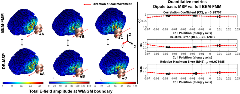
As another example, we simulated a case where the coil moves along a straight line adjacent to the head with coil orientation fixed parallel to the trajectory as shown in Fig. 7. The spatial distribution of the total E-fields again shows a high degree of similarity between the full BEM-FMM and the MSP dipole basis approximation (Fig. 7 (A)). In addition, we calculated the quantitative error metrics and plotted the results as a function of the coil position (Fig. 7 (B)). The results of the accuracy metrics show an inverted u-shaped profile indicating that the approximation accuracy decreases slightly when the coil is farther away and not fully tangential to the scalp. Since in most real TMS sessions the coil is both nearly tangential to and in close proximity of the scalp, the MSP dipole basis approach is well suited for accurate realtime E-field neuronavigation applications. A higher magnification version of Fig. 7 (A) is shown in Appendix Fig. A1 for enhanced visualization of the differences between the spatial E-field profiles.
Fig. 7.
(A) Comparison between the BEM-FMM solver and the dipole basis MSP approximation of the total E-field for representative coil positions along the line of simulated coil movement. (B) The accuracy metrics of CC, RE and RME plotted as a function of the coil position.
3.2. Quantification of the MSP accuracy across the stimulation targets and subjects
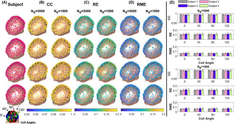
To further analyze the accuracy of the dipole basis MSP approximation, we simulated a TMS coil (MagVenture Cool-B35) at 256 different scalp locations. For each location, the coil was assumed to be tangential to scalp and then oriented at 0, 45, 90 and 135 degrees with respect to the anterior-posterior axis in the tangent plane. The total E-field for every coil location/orientation was calculated using the dipole basis MSP approximation method and the full BEM-FMM solver. For the ground truth BEM-FMM method used for benchmarking, the solution converged to a residual of 0.00001 in 20 iterations; increasing the number further does in general not affect the overall accuracy (Makarov et al., 2020). We compared the results of the two methods using the accuracy metrics specified in the Methods section using the WM as the surface of interest. The simulations and subsequent accuracy assessments were performed on four individual subject’s head meshes each comprising of approximately 1M facets.
Figure 8 shows the accuracy metric results for different subjects for two cases of 3000 and 1500 dipole basis function sets. From Fig. 8 (B) we observe that the CC metric is very high (>0.98) across all subjects and coil orientations, indicating that the E-field patterns produced by the dipole basis MPS are spatially consistent with the ground truth for both dipole basis set sizes. The RE metric that is measured on the full surface with over 250k triangular elements shown in Fig. 8 (C) is on average in the range of 5~15% for both dipole basis sizes, indicating that there are some differences in the electric field amplitudes between the two methods. However, the average RME that quantifies differences of the largest E-field values at the ‘hot spot’ was about 5.1% and 5.7% for 3000 and 1500 dipoles cases, respectively, as shown in Fig. 8 (D). The higher degree of consistency in the CC and RME relative to the RE indicates that the differences are predominantly in the smaller values of the E-fields that are less critical especially for the near real-time guidance applications. As illustrated in Fig. 8 (E), the accuracy metrics are comparable for various coil orientations and number of dipole functions among all subjects indicating no significant differences in the overall performance.
Fig. 8.
(A) A total of 256 coil positions were defined around the scalp surface of each subject. The inset shows the four coil orientations used. (B-D) The spatial profiles of the error metrics CC, RE and RME averaged across the four coil orientations at each location for both 3000 and 1500 dipole basis function sets. (E) The mean and std of the error metrics shown across subjects and coil orientations.
3.3. Computational performance evaluation
The BEM-FMM requires 0.8 s to calculate the incident E-field of a dipole and approximately 20 s to obtain the total E-field (roughly 2 s for each iteration of GMRES with 10 iteration for convergence to the residual of 0.0001). However, we can compute the total E-fields of dipoles in parallel to speed up the pre-calculation step. When using MATLAB Parallel Computing Toolbox assigned with 12 workers, this approach reduced the pre-calculation time by a factor of 3. For this study, for the main accuracy comparisons presented above we used 1M facet head models with 3000 dipole basis functions (1000 locations with three orthogonal dipoles each) with 10 GMRES iterations. However, cutting down the number of GMRES iterations and reducing the number of dipoles by half for the MSP pre-calculation would reduce the computation times further without significant increase in the error metrics.
We evaluated the computational runtimes for both the MSP and the near real-time step on a more typical, mid-range, desktop PC system as well as a high-performance CPU system. For more accurate and informative comparisons, both computer systems were running Windows OS to exclude possible differences of compiling the FMM library as well as running GMRES/MATLAB on different platforms. The mid- and high-performance systems used were a Xeon E5–2360 / 128 GB RAM and a Xeon(R) Gold 6226R / 192 GB RAM, respectively. Table 1 shows the average runtimes on the mid-range and high-performance CPUs for the pre-calculation step of the dipole basis MSP approximation pipeline for different numbers of basis functions and GMRES iterations used on 1M facet head meshes. Similarly, in Table 2, the speed of the near real-time step on these two systems is compared for different numbers of dipole basis functions and mesh triangulation densities.
Table 1.
The computational benchmarking of the pre-calculation step for different GMRES iteration schemes and dipole basis set configurations on mid and high-performance CPUs
| Number of Dipoles Nd and GMRES iterations Ni | Pre-calculation step Xeon E5-2360 / 128 GB |
Pre-calculation step Xeon(R) Gold 6226R / 192 GB |
||||
|---|---|---|---|---|---|---|
| Ainc, Atot | W | Ainc, Atot | W | |||
|
| ||||||
| Nd = 3000, Ni = 10 | 18.2 hrs | 116 s | 15 s | 10.3 hrs | 74 s | 4 s |
| Nd = 3000, Ni = 5 | 12.2 hrs | 116 s | 15 s | 5.8 hrs | 74 s | 4 s |
| Nd = 1500, Ni = 10 | 10 hrs | 33 s | 15 s | 5.7 hrs | 15 s | 4 s |
| Nd = 1500, Ni = 5 | 5.5 hrs | 33 s | 15 s | 2.8 hrs | 15 s | 4 s |
Table 2.
The near real-time computational benchmarking for different dipole basis set sizes on standard and high-performance CPUs (reported times are in milliseconds).
| Number of facets | Nd | Near real-time step Xeon E5-2360 / 128 GB |
Near real-time step Xeon(R) Gold 6226R / 192 GB |
||||||
|---|---|---|---|---|---|---|---|---|---|
| Einc | Total time | Einc | Total time | ||||||
|
| |||||||||
| 120 K | 3000 | 8 | 180 | 182 | 370 | 5 | 8 | 80 | 165 |
| 90 K | 3000 | 5 | 132 | 134 | 269 | 5 | 68 | 66 | 139 |
| 60 K | 3000 | 4 | 92 | 92 | 188 | 3 | 47 | 44 | 94 |
| 120 K | 1500 | 8 | 85 | 85 | 178 | 4 | 45 | 42 | 91 |
| 90 K | 1500 | 5 | 67 | 66 | 138 | 3 | 38 | 34 | 75 |
| 60 K | 1500 | 4 | 46 | 47 | 97 | 2 | 25 | 23 | 50 |
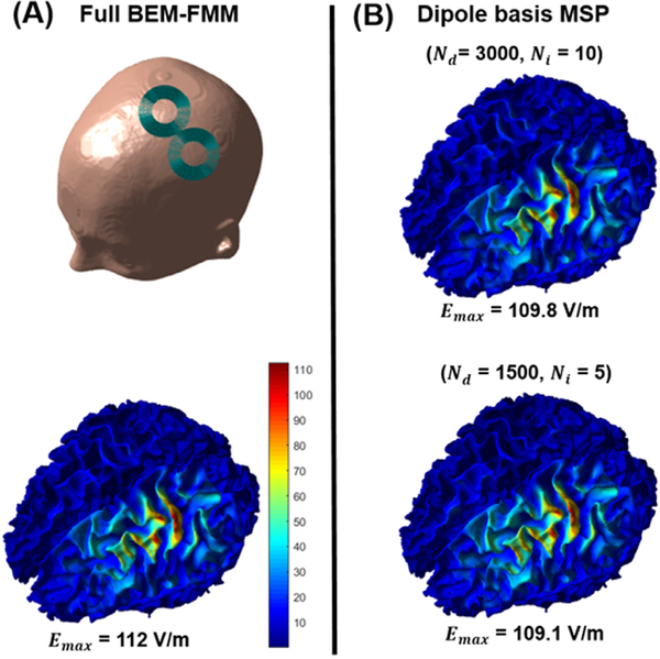
The dipole set pre-calculation using BEM-FMM takes approximately 18 hours with parallel processing utilized for the 3000 dipole set with 10 GMRES iterations on the mid-performance CPU. However, this time can be further reduced to 5.5 hours using only 1500 dipoles and 5 iterations of the GMRES without visual degradation of results as shown in Fig. 9. Additionally, the pre-calculation time can be cut down to less than 3 hours for the practical laboratory usage case in which a high-performance CPU (Xeon(R) Gold 6226R / 192 GB RAM) is used.
Fig. 9.
(A) The simulated Cool-B35 coil position (top row) and the ground truth total E-field of the calculated with BEM-FMM and 20 GMRES iterations (bottom row). (B) The corresponding E-field result obtained by dipole basis MSP approximation with full 3000 dipole basis set and 10 GMRES iterations (top row) and the reduced 1500 dipole set with 5 GMRES iterations (bottom row).
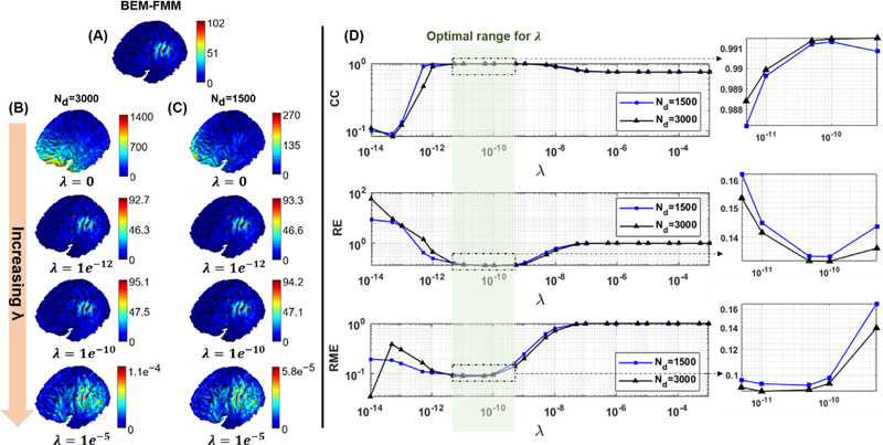
Depending on the density of the surface mesh triangulation we can achieve the 100 ms calculation benchmarks for both 3000 and 1500 dipole basis sets on a higher-end CPU (Xeon(R) Gold 6226R / 192 GB RAM) system. The mid-range system (E5–2360 / 128 GB RAM) can perform the near real-time calculations under 100 ms for the case of 1500 dipoles on a mesh with 60K facets that would also be practically sufficient for the interactive E-field visualization. In general, as shown in Fig. 8 and Appendix Fig. B1, the reduced 1500 dipole basis set yields very similar accuracy metrics as the 3000 dipole set as long as the regularization parameter λ is selected within an optimal range to avoid possible overfitting/underfitting problems (see, Appendix B). Overall, the results show that near real-time computations run in the ‘frame rate’ range of 2.7–5.5 Hz and 6–10 Hz on moderate and high-end CPUs, respectively, depending on the mesh resolution. The corresponding numbers are 5.6–10 Hz and 11–20 Hz for the 1500 dipole basis set.
The matrices needed for the near real-time step Atot and W require ~16 GB of memory each for 3000 dipole basis set, and is less than 1 GB so from a RAM perspective ~ 32 GB would be sufficient. The amount of allocated cache memory to perform near real-time operations are determined by different factors such as the method of initializing the matrices by the operating system, the amount of free cache assigned to the task, the cache hit and miss ratio, etc. However, to characterize the necessary minimal overhead during the runtime, we estimated the peak used memory using the MATLAB ”profiler” function on the high-end system as follows: The computation of Einc, , and for a 3000 dipole basis set on a 120K faceted mesh requires 9 MB, 11.1 MB and 13.3 MB, respectively. Reducing the number of dipoles to 1500 decreases the required memory for matrix operations to 9 MB, 5.6 MB and 7.4 MB, respectively. On a mid-range performance system, the required memory for computation of Einc, , and with the 3000 dipole basis set was 15.5 MB, 17.3 MB and 19.4 MB, respectively, while for the 1500 dipole case the corresponding numbers were 15.5 MB, 12 MB and 14.1 MB. Note that the amount of memory needed for the interpolation step remains constant for both 3000 and 15000 dipole functions since the size of is fixed and independent of the number of dipoles.
4. Discussion
We propose a new fast method to calculate the induced E-field of a rapidly moving TMS coil on high-resolution head models utilizing the BEM-FMM engine. The method is based on defining a set of stationary magnetic dipoles as local basis functions for each subject. This fundamental basis set depends solely on the subject’s anatomy and hence we consider this the MSP of the subject. Furthermore, the incident E-field (i.e., the field in free space) of any coil depends solely on the wire winding geometry and the relative position/orientation of the coil. Our key observation is that the MSP of the subject and the coil can be connected through the incident E-fields (that is, the fields in free space) since their values at the conductivity boundaries also determine the total E-field. The basic physical principles of TMS modeling are well established and related recent work employing surface currents basis exists in the field of MRI to assess the “ultimate SNR” of receive coils as well as to design to minimize peripheral nerve stimulation (Davids et al., 2020a, 2020b; Guérin et al., 2017). The related methodologies of using surface current distributions have been proposed for designing TMS coils (Roth et al., 1994) as well as for practical optimization of coil designs (Koponen et al., 2015) and their numerical modeling (Gomez et al., 2020). A minor theoretical difference is that in principle the surface current distributions correspond to using equivalent magnetic dipole distributions that are radially oriented (to restrict the corresponding current flow along the surface), while in our method all three cartesian dipole orientations are included to efficiently approximate the TMS coil with arbitrary position / orientation. This is clearly visible in Fig. 2 for the case when the coil is not tangential to the surface, and all three components are employed to accurately ‘match’ the E-fields. However, the main novelty is the combination of fast and memory-efficient BEM-FMM approach for the MSP pre-calculation and the incident field matching process for the moving coil presented here to reach near real-time performance. The proposed approach enables, for the first time, a straightforward implementation for rapid visualization of the E-fields on high-resolution cortical meshes for TMS neuronavigation as the near real-time computational step comprises of a single interpolation and two matrix multiplications.
Another method using auxiliary dipoles has been concurrently developed and recently published to accelerate the computational targeting of TMS (Gomez et al., 2021). The method utilizes the principle of reciprocity and a local set of dipoles to rapidly estimate total E-field distributions to facilitate targeting. Apart from using dipoles, this method is very different from the MSP approach presented here in terms of the computational strategy: The use of the reciprocity and a set of dipoles around the target area enables relatively fast estimation of the desired coil position/orientation, but this approximation is inherently local as both the dipole basis set and the E-fields are only estimated in the vicinity of the region of interest. On the other hand, our MSP approach utilizes the BEM-FMM method and a global basis set surrounding the entire head to approximate the E-fields of an arbitrary moving TMS coil inside a general volume conductor model of the head. The main downside is that the pre-computation takes several hours even with a modern high-performance CPU system. However, this step needs to be done only once per subject and can be included as a part of automatic pre-processing pipeline. Furthermore, as the BEM-FMM solution provides both the incident fields and the conductivity boundary surface charge distributions responsible for the secondary fields, with a single further application of the FMM algorithm the E-fields can be estimated anywhere in the 3D space if desired (see, Fig. 1), rendering the method a highly flexible general-purpose modeling tool.
Standard optical tracking cameras (e.g., Polaris Spectra, NDI, Northern Digital Inc, Canada) used in TMS navigation systems provide frame rates up to ~60 Hz. However, in order to avoid abrupt visual change in coil positions, the commercial TMS neuronavigator tracking data is smoothed and updated at rates of 10–15 Hz to continuously visualize the coil positions (LOCALITE GmbH, Bonn, Germany, Personal Communication). For our approach, near real-time step takes around 100 ms for a full WM mesh with 120K facets making it fast enough to keep up with the data stream with a constant processing delay that will not significantly hamper the operator performing the coil positioning. Comparison of the MSP dipole approximation with the BEM-FMM results indicates a high similarity in the intensity and spatial distributions of the calculated E-fields as was quantified by the error metrics across multiple stimulation locations and subjects. Furthermore, since the correlation and maximum E-field intensity metrics indicate that the differences arise predominantly from the small values outside the hot spot, the method is well suited especially for the ‘free-hand’ neuronavigation guidance applications where the peripheral values are typically ignored.
Due to the linearized nature of the near real-time step, further increases in the computational speed can be obtained simply by down-sampling the surface meshes. A significant advantage offered by the MSP-basis function approach is that this down-sampling can be performed after computing the E-field distributions with high numerical accuracy to avoid accumulation of errors. Furthermore, the E-fields can be also re-sampled to be defined on the surface vertices instead of faces, resulting in further reductions in the time needed to complete the real-time step. For ultimate computational speed, it may be possible to reduce mesh complexity, so they fit in the limited memory of a GPU for an even faster frame refresh rate. The exact trade-offs in performance vs. spatial sampling for practical TMS navigation applications will require further development including dedicated 3D rendering system.
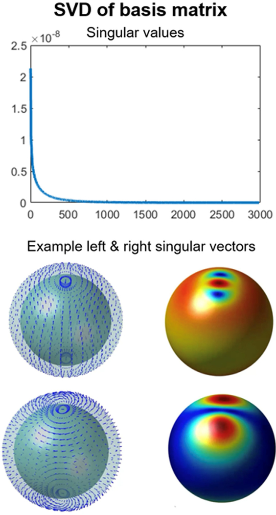
Obtaining the MSP of a subject requires several hours of CPU time and must be done in advance. However, when running multiple BEM-FMM solvers in parallel the total computation time is reduced by a factor of 3. The most obvious way to reduce the pre-computation time further is to use a smaller number of the dipole basis functions. This will also reduce the accuracy of the approximation to some degree, but our initial results shown in Fig. 9 indicate that ~500 locations each with three orthogonal dipoles may be sufficient. On the other hand, the number of dipole basis functions can be also reduced by applying the Singular Value Decomposition (SVD) to Ainc. With this approach, the spatially overlapping local dipole basis functions can be compressed to a smaller number of orthonormal global basis functions comprising of the singular vectors. This significantly reduces the computational cost of calculating the MSP of each subject without losing significant information as the SVD basis set can be constructed prior to running the full BEM-FMM algorithm for the total E-fields Atot (the SVD approach for the spherical model is illustrated in Appendix Fig. C1).
Apart from the interactive guidance for “computational neuronavigation”, the dipole basis MSP approximation method can be used to assist in planning a TMS study. For example, the MSP-approach can be used to rapidly calculate the induced E-field at a given target location for various coil positions to select the optimal one based on user-specified criteria (see, e.g., (Nummenmaa et al., 2014)). During the experiment, snapshots of the E-fields at the timepoints of the delivered TMS stimuli can be stored for comparison with biophysical markers such as reaction times or electrophysiological responses. These types of ‘E-field data’ have been used for off-line analysis by several studies (see, e.g., (Ahveninen et al., 2013), (Raij et al., 2018)) but the near real-time capability would make this approach available also for closed-loop TMS investigations (Bergmann et al., 2012; Kraus et al., 2016; Meincke et al., 2016) and computationally more intensive pulse-specific offline analyses.
In addition to enhancing existing approaches, we anticipate the MSP-basis approach to be useful for development of new TMS technologies that utilize E-field modeling. For instance, a recent technological development project aims at rendering a holographic brain MRI on top of the patient’s head using the augmented reality headset (Sathyanarayana et al., 2020) for a novel type of neuronavigation system. The MSP approach may be particularly useful for such application where the computational resources available for the real-time step are limited by the Augmented Reality (AR) headset hardware and a lightweight and simple ‘linearized’ implementation is preferred. We also anticipate the ongoing multichannel TMS technology development (Han et al., 2004; Jiang et al., 2013; Navarro de Lara et al., 2020) to benefit from the proposed approach as the E-fields of several coils need to be rapidly evaluated for computational targeting. Future work includes optimizing the MSP basis set selection such that it provides maximal accuracy with the smallest number of basis functions as well as further improvements on the numerical efficiency of the BEM-FMM algorithm.
5. Conclusion
The presented dipole basis MSP approach provides a general-purpose methodology to rapidly evaluate TMS-induced E-fields using a high-resolution subject-specific head model. The approach can be adopted for interactive guidance for TMS targeting and dosing when used in conjunction with a neuronavigation system. Other possible future applications include stimulation experiment planning to optimize targeting/dosing, offline analysis with pulse-specific E-field estimates, as well as providing a near real-time E-field data stream for closed-loop TMS setups.
Acknowledgments
We want to thank Henrik Corfitzen and Yordan Todorov (MagVenture, Farum, Denmark) for TMS coil specifications and Martin Bublat and Patrik Kunz (Localite, Bonn, Germany) for discussions about neuronavigation tracking systems. The research was supported by NIH R00EB015445, R01MH111829, P41EB030006, R21MH116484, and 5R01NS104585 and the Rappaport Foundation.
Appendix A. High resolution results for dipole basis MSP comparison with BEM-FMM
Fig. A1.
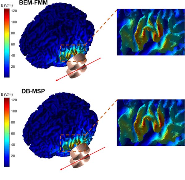
Total E-field calculated by BEM-FMM and dipole basis MSP on the WM surface with a zoom-in view of the ‘hot spot’.
Appendix B. Effect of the regularization parameter value on the dipole basis approximation
Fig. B1.
(A) The reference total E-field calculated by the BEM-FMM method. (B) The DB-MSP approximations for increasing values of λ for the 3000 dipole basis set. (C) Corresponding results for 1500 dipole basis set. (D) Effects of the regularization parameter on the accuracy metrics. When the value of λ is between 5e−12 and 5e−10 all the metrics remain within a reasonable range. Increasing λ to be more than 1e−9 still provides an acceptable spatial distribution for the real-time visualization of the E-field in terms of CC, however the intensity of the approximated E-field is reduced due to the bias caused by over-regularization. Similarly, choosing a smaller value of λ tends to cause a numerical instability in the approximation and a high degree of inconsistency both in the spatial distribution and intensity of the E-field.
Appendix C. Reducing computational cost using singular values decomposition
Fig. C1.
The singular values of the dipole basis set (top row) can be used to identify the required number of global basis functions (bottom row) to reduce the computational burden without losing information.
Footnotes
Declaration of competing interest
M.D., B.G., J.M., B.R., and M.S.H declare no competing interests. S.N.M is partially employed by NEVA Electromagnetics, LLC, Yarmouth Port, MA, that is a for-profit company with commercial interest in electromagnetic human modeling and neuromodulation device development. L.N. is a named inventor in a TMS-related patent (US9924889). A.N., M.D., S.N.M., and T.R. are named inventors in TMS-related patent applications.
Data and code availability statement
The general-purpose TMS modeling MATLAB package used for computational simulations is freely available to download from: https://tmscorelab.github.io/TMS-Modeling-Website/. The additional MATLAB analysis scripts for the specific models supporting the findings of this study are available from the corresponding author A.N. on request. The human head models employed in this study are freely available for download from: https://www.nevaelectromagnetics.com/high-resolution-head-models
Restrictions apply to the availability of the models of commercial MagVenture coils, which were used under permission of MagVenture (Farum, Danemark).
References
- Ahveninen J, Huang S, Nummenmaa A, Belliveau JW, Hung A-Y, Jääskeläinen IP, Rauschecker JP, Rossi S, Tiitinen H, Raij T, 2013. Evidence for distinct human auditory cortex regions for sound location versus identity processing. Nat. Commun. 4, 1–8. [DOI] [PMC free article] [PubMed] [Google Scholar]
- Baker BB, Copson ET, 2003. The mathematical theory of Huygens’ principle. American Mathematical Soc. [Google Scholar]
- Barker AT, Jalinous R, Freeston IL, 1985. Non-invasive magnetic stimulation of human motor cortex. Lancet (London, England) doi: 10.1016/s0140-6736(85)92413-4, https://doi.org/. [DOI] [PubMed] [Google Scholar]
- Bergmann TO, Mölle M, Schmidt MA, Lindner C, Marshall L, Born J, Siebner HR, 2012. EEG-guided transcranial magnetic stimulation reveals rapid shifts in motor cortical excitability during the human sleep slow oscillation. J. Neurosci. 32, 243–253. [DOI] [PMC free article] [PubMed] [Google Scholar]
- Carmi L, Tendler A, Bystritsky A, Hollander E, Blumberger DM, Daskalakis J, Ward H, Lapidus K, Goodman W, Casuto L, Feifel D, Barnea-Ygael N, Roth Y, Zangen A, Zohar J, 2019. Efficacy and Safety of Deep Transcranial Magnetic Stimulation for Obsessive-Compulsive Disorder: A Prospective Multicenter Randomized Double-Blind Placebo-Controlled Trial. Am. J. Psychiatry 176, 931–938. doi: 10.1176/appi.ajp.2019.18101180, https://doi.org/. [DOI] [PubMed] [Google Scholar]
- Chen M, Mogul DJ, 2009. A structurally detailed finite element human head model for simulation of transcranial magnetic stimulation. J. Neurosci. Methods 179, 111–120. doi: 10.1016/j.jsneumeth.2009.01.010, https://doi.org/. [DOI] [PubMed] [Google Scholar]
- Cortes M, Elder J, Rykman A, Murray L, Avedissian M, Stampas A, Thickbroom GW, Pascual-Leone A, Krebs HI, Valls-Sole J, 2013. Improved motor performance in chronic spinal cord injury following upper-limb robotic training. NeuroRehabilitation 33, 57–65. [DOI] [PMC free article] [PubMed] [Google Scholar]
- Davids M, Guérin B, Klein V, Wald LL, 2020a. Optimization of MRI Gradient Coils with Explicit Peripheral Nerve Stimulation Constraints. IEEE Trans. Med. Imaging.. [DOI] [PMC free article] [PubMed] [Google Scholar]
- Davids M, Guérin B, Wald LL, 2020b. Assembly of a PNS predicting “P-matrix” on a Huygens’ surface for rapid PNS assessment of 2D or 3D gradient coil windings. In: Proc. 28th Annu. Meet. ISMRM. Sydney, Aust.. [Google Scholar]
- Gomez LJ, Dannhauer M, Koponen LM, Peterchev A V, 2020. Conditions for numerically accurate TMS electric field simulation. Brain Stimul 13, 157–166. [DOI] [PMC free article] [PubMed] [Google Scholar]
- Gomez LJ, Dannhauer M, Peterchev A V. Fast computational optimization of TMS coil placement for individualized electric field targeting. Neuroimage 228, 117696. [DOI] [PMC free article] [PubMed] [Google Scholar]
- Guérin B, Villena JF, Polimeridis AG, Adalsteinsson E, Daniel L, White JK, Wald LL, 2017. The ultimate signal-to-noise ratio in realistic body models. Magn. Reson. Med. 78, 1969–1980. [DOI] [PMC free article] [PubMed] [Google Scholar]
- Han BH, Chun IK, Lee SC, Lee SY, 2004. Multichannel Magnetic Stimulation System Design Considering Mutual Couplings among the Stimulation Coils. IEEE Trans. Biomed. Eng. 51, 812–817. doi: 10.1109/TBME.2004.824123, https://doi.org/. [DOI] [PubMed] [Google Scholar]
- Htet AT, Saturnino GB, Burnham EH, Noetscher GM, Nummenmaa A, Makarov SN, 2019. Comparative performance of the finite element method and the boundary element fast multipole method for problems mimicking transcranial magnetic stimulation (TMS). J. Neural Eng. 16. doi: 10.1088/1741-2552/aafbb9, https://doi.org/. [DOI] [PMC free article] [PubMed] [Google Scholar]
- Ishkhanyan B, Michel Lange V, Boye K, Mogensen J, Karabanov A, Hartwigsen G, Siebner HR, 2020. Anterior and posterior left inferior frontal gyrus contribute to the implementation of grammatical determiners during language production. Front. Psychol. 11, 685. [DOI] [PMC free article] [PubMed] [Google Scholar]
- Jiang R, Jansen BH, Sheth BR, Chen J, 2013. Dynamic multi-channel TMS with reconfigurable coil. IEEE Trans. neural Syst. Rehabil. Eng. a Publ. IEEE Eng. Med. Biol. Soc. 21, 370–375. doi: 10.1109/TNSRE.2012.2226914, https://doi.org/. [DOI] [PubMed] [Google Scholar]
- Koponen LM, Nieminen JO, Ilmoniemi RJ, 2015. Minimum-energy coils for transcranial magnetic stimulation: Application to focal stimulation. Brain Stimul 8, 124–134. doi: 10.1016/j.brs.2014.10.002, https://doi.org/. [DOI] [PubMed] [Google Scholar]
- Kraus D, Naros G, Bauer R, Khademi F, Leão MT, Ziemann U, Gharabaghi A, 2016. Brain state-dependent transcranial magnetic closed-loop stimulation controlled by sensorimotor desynchronization induces robust increase of corticospinal excitability. Brain Stimul 9, 415–424. [DOI] [PubMed] [Google Scholar]
- Kreuzer PM, Downar J, de Ridder D, Schwarzbach J, Schecklmann M, Langguth B, 2019. A comprehensive review of dorsomedial prefrontal cortex rTMS utilizing a double cone coil. Neuromodulation Technol. Neural Interface 22, 851–866. [DOI] [PubMed] [Google Scholar]
- Lipton RB, Dodick DW, Silberstein SD, Saper JR, Aurora SK, Pearlman SH, Fischell RE, Ruppel PL, Goadsby PJ, 2010. Single-pulse transcranial magnetic stimulation for acute treatment of migraine with aura: a randomised, double-blind, parallel-group, sham-controlled trial. Lancet. Neurol. 9, 373–380. doi: 10.1016/S1474-4422(10)70054-5, https://doi.org/. [DOI] [PubMed] [Google Scholar]
- Makarov SN, Noetscher GM, Raij T, Nummenmaa A, 2018. A quasi-static boundary element approach with fast multipole acceleration for high-resolution bioelectromagnetic models. IEEE Trans. Biomed. Eng. 65, 2675–2683. [DOI] [PMC free article] [PubMed] [Google Scholar]
- Makarov SN, Wartman WA, Daneshzand M, Fujimoto K, Raij T, Nummenmaa A, 2020. A software toolkit for TMS electric-field modeling with boundary element fast multipole method: An efficient MATLAB implementation. J. Neural Eng. doi: 10.1088/1741-2552/ab85b3, https://doi.org/. [DOI] [PubMed] [Google Scholar]
- Meincke J, Hewitt M, Batsikadze G, Liebetanz D, 2016. Automated TMS hotspot-hunting using a closed loop threshold-based algorithm. Neuroimage 124, 509–517. [DOI] [PubMed] [Google Scholar]
- Miranda PC, Correia L, Salvador R, Basser PJ, 2007. Tissue heterogeneity as a mechanism for localized neural stimulation by applied electric fields. Phys. Med. Biol. 52, 5603–5617. doi: 10.1088/0031-9155/52/18/009, https://doi.org/. [DOI] [PubMed] [Google Scholar]
- Navarro de Lara LI, Daneshzand M, Mascarenas A, Paulson D, Pratt K, Okada Y, Raij T, Makarov SN, Nummenmaa A, 2020. A 3-axis coil design for multichannel TMS arrays. Neuroimage, 117355. [DOI] [PMC free article] [PubMed] [Google Scholar]
- Nummenmaa A, McNab JA, Savadjiev P, Okada Y, Hämäläinen MS, Wang R, Wald LL, Pascual-Leone A, Wedeen VJ, Raij T, 2014. Targeting of white matter tracts with transcranial magnetic stimulation. Brain Stimul 7, 80–84. [DOI] [PMC free article] [PubMed] [Google Scholar]
- Nummenmaa A, Stenroos M, Ilmoniemi RJ, Okada YC, Hämäläinen MS, Raij T, 2013. Comparison of spherical and realistically shaped boundary element head models for transcranial magnetic stimulation navigation. Clin. Neurophysiol. Off. J. Int. Fed. Clin. Neurophysiol. 124, 1995–2007. doi: 10.1016/j.clinph.2013.04.019, https://doi.org/. [DOI] [PMC free article] [PubMed] [Google Scholar]
- O’Reardon JP, Solvason HB, Janicak PG, Sampson S, Isenberg KE, Nahas Z, McDonald WM, Avery D, Fitzgerald PB, Loo C, Demitrack MA, George MS, Sackeim HA, 2007. Efficacy and safety of transcranial magnetic stimulation in the acute treatment of major depression: a multisite randomized controlled trial. Biol. Psychiatry 62, 1208–1216. doi: 10.1016/j.biopsych.2007.01.018, https://doi.org/. [DOI] [PubMed] [Google Scholar]
- Pavon JH, Schneider-Garces N, Begnoche J, Raij T, 2019. Effects of paired associative stimulation asynchrony on modulating cortico-cortical connectivity. Brain Stimul. Basic, Transl. Clin. Res. Neuromodulation 12, 582. [Google Scholar]
- Picht T, Schmidt S, Brandt S, Frey D, Hannula H, Neuvonen T, Karhu J, Vajkoczy P, Suess O, 2011. Preoperative functional mapping for rolandic brain tumor surgery: comparison of navigated transcranial magnetic stimulation to direct cortical stimulation. Neurosurgery 69, 581–588. doi: 10.1227/NEU.0b013e3182181b89, [DOI] [PubMed] [Google Scholar]
- Raij T, Nummenmaa A, Marin M-F, Porter D, Furtak S, Setsompop K, Milad MR, 2018. Prefrontal cortex stimulation enhances fear extinction memory in humans. Biol. Psychiatry 84, 129–137. [DOI] [PMC free article] [PubMed] [Google Scholar]
- Rossi S, Hallett M, Rossini PM, Pascual-Leone A, 2009. Safety, ethical considerations, and application guidelines for the use of transcranial magnetic stimulation in clinical practice and research. Clin. Neurophysiol. Off. J. Int. Fed. Clin. Neurophysiol. 120, 2008–2039. doi: 10.1016/j.clinph.2009.08.016, https://doi.org/. [DOI] [PMC free article] [PubMed] [Google Scholar]
- Roth BJ, Cohen LG, Hallett M, Friauf W, Basser PJ, 1990. A theoretical calculation of the electric field induced by magnetic stimulation of a peripheral nerve. Muscle Nerve 13, 734–741. doi: 10.1002/mus.880130812, https://doi.org/. [DOI] [PubMed] [Google Scholar]
- Roth BJ, Momen S, Turner R, 1994. Algorithm for the design of magnetic stimulation coils. Med. Biol. Eng. Comput. 32, 214–216. [DOI] [PubMed] [Google Scholar]
- Ruohonen J, Karhu J, 2010. Navigated transcranial magnetic stimulation. Neurophysiol. Clin. 40, 7–17. doi: 10.1016/j.neucli.2010.01.006, https://doi.org/. [DOI] [PubMed] [Google Scholar]
- Saad Y, Schultz MH, 1986. GMRES: A generalized minimal residual algorithm for solving nonsymmetric linear systems. SIAM J. Sci. Stat. Comput. 7, 856–869. [Google Scholar]
- Sathyanarayana S, Leuze C, Hargreaves B, Daniel B, Wetzstein G, Etkin A, Bhati MT, McNab JA, 2020. Comparison of head pose tracking methods for mixed-reality neuronavigation for transcranial magnetic stimulation. In: Fei B, Linte CA (Eds.), Medical Imaging 2020: Image-Guided Procedures. Robotic Interventions, and Modeling. SPIE, pp. 147–154. doi:10.1117/12.254791710.1117/12.2547917https://doi.org/https://doi.org/. [Google Scholar]
- Saturnino GB, Madsen KH, Thielscher A, 2019a. Electric field simulations for transcranial brain stimulation using FEM: an efficient implementation and error analysis. J. Neural Eng. 16, 66032. [DOI] [PubMed] [Google Scholar]
- Saturnino GB, Puonti O, Nielsen JD, Antonenko D, Madsen KH, Thielscher A, 2019b. Simnibs 2.1: A comprehensive pipeline for individualized electric field modelling for transcranial brain stimulation. In: Brain and Human Body Modeling. Springer, Cham, pp. 3–25. [PubMed] [Google Scholar]
- Stenroos M, Koponen LM, 2019. Real-time computation of the TMS-induced electric field in a realistic head model. Neuroimage 203, 116159. doi: 10.1016/j.neuroimage.2019.116159, https://doi.org/. [DOI] [PubMed] [Google Scholar]
- Thielscher A, Antunes A, Saturnino GB, 2015. Field modeling for transcranial magnetic stimulation: a useful tool to understand the physiological effects of TMS? In: 2015 37th Annual International Conference of the IEEE Engineering in Medicine and Biology Society (EMBC), pp. 222–225. [DOI] [PubMed] [Google Scholar]
- Thielscher A, Kammer T, 2002. Linking physics with physiology in TMS: a sphere field model to determine the cortical stimulation site in TMS. Neuroimage 17, 1117–1130. doi: 10.1006/nimg.2002.1282, https://doi.org/. [DOI] [PubMed] [Google Scholar]
- Thielscher A, Opitz A, Windhoff M, 2011. Impact of the gyral geometry on the electric field induced by transcranial magnetic stimulation. Neuroimage 54, 234–243. doi: 10.1016/j.neuroimage.2010.07.061, https://doi.org/. [DOI] [PubMed] [Google Scholar]
- Windhoff M, Opitz A, Thielscher A, 2013. Electric field calculations in brain stimulation based on finite elements: An optimized processing pipeline for the generation and usage of accurate individual head models. Hum. Brain Mapp. 34, 923–935. doi: 10.1002/hbm.21479, https://doi.org/. [DOI] [PMC free article] [PubMed] [Google Scholar]
- Yokota T, Maki T, Nagata T, Murakami T, Ugawa Y, Laakso I, Hirata A, Hontani H, 2019. Real-time estimation of electric fields induced by transcranial magnetic stimulation with deep neural networks. Brain Stimul 12, 1500–1507. doi: 10.1016/j.brs.2019.06.015, https://doi.org/. [DOI] [PubMed] [Google Scholar]
Associated Data
This section collects any data citations, data availability statements, or supplementary materials included in this article.
Data Availability Statement
The general-purpose TMS modeling MATLAB package used for computational simulations is freely available to download from: https://tmscorelab.github.io/TMS-Modeling-Website/. The additional MATLAB analysis scripts for the specific models supporting the findings of this study are available from the corresponding author A.N. on request. The human head models employed in this study are freely available for download from: https://www.nevaelectromagnetics.com/high-resolution-head-models
Restrictions apply to the availability of the models of commercial MagVenture coils, which were used under permission of MagVenture (Farum, Danemark).


