

Abstract
Machines operating in aqueous environments may be subjected to cavitation damage during operation. This study aims to evaluate the cavitation resistance of WC-10Co4Cr and WC-20CrC-7Ni coatings under cavitation erosion conditions with additional electrochemical effects. The coatings were deposited on AISI 1040 steel substrates using a high velocity air fuel thermal spray process. The microstructure of the coatings was observed by a scanning electron microscope, while their phase composition was analyzed using an energy-dispersive microanalysis system. In addition, the microhardness of the coatings and substrate was measured, and the surface topography of the eroded surface layers was observed using a 3D optical profilometer. The results revealed that the cavitation resistance of the WC-20CrC-7Ni coatings was better than that of the WC-10Co4Cr coatings. The observation of the structure and surface topography made it possible to identity the reasons for the differences between the cavitation resistance of both coatings: The WC-20CrC-7Ni coatings had a finer grain structure, lower pore density, and lower as-sprayed surface roughness. These differences, along with the presence of a high Cr and Ni content in the feedstock powder, that increased the coating corrosion resistance, contributed to improving the cavitation resistance and reducing the material loss of the WC-20CrC-7Ni coatings.
Keywords: cavitation erosion resistance, HVAF coatings, microstructure, surface topography, ultrasonic vibration method, WC-10Co4Cr, WC-20CrC-7Ni
Introduction
Hydro turbine blades, valves, pump impellers, and marine ship propellers are critical components of machines operating in aqueous environments. They are often exposed to cavitation damage during operation (Ref 1).
A series of small holes or pits are formed in the component’s surface due to the frequent formation and collapse of cavitation bubbles (cavities) near the surface, causing material damage (Ref 2-6). High pressure shock waves and liquid micro-jets can be produced during the collapse of cavitation bubbles, resulting in plastic deformation, fatigue, and, consequently, material loss (Ref 7-10). The shock wave pressure emitted during the collapse process can reach as high as 1500 MPa (Ref 2, 11). The velocities of liquid micro-jets exceed 120 m/s (Ref 12-14).
One of the most effective ways to combat cavitation damage is covering the surfaces of components with coatings (Ref 1). Various coatings and surface engineering techniques are used to prevent cavitation erosion or reduce it as much as possible. Ceramic-metallic (cermet) coatings are extensively used in thermal spraying to prepare dense-protective coatings with a high level of hardness to serve in a wide range of industrial applications requiring resistance against wear, corrosion (Ref 15-22), and cavitation (Ref 23-28). Cermet coatings are generally constituted of a combination of hard materials, e.g., WC and Cr3C2, with one or more matrix metal, e.g., Co and Ni (Ref 15, 29).
A matrix with a tungsten carbide, e.g., WC-Co with 12 or 17% Co, has previously been used to improve wear resistance (Ref 21) and increase cavitation erosion resistance (Ref 30, 31). Moreover, adding Cr to the matrix, e.g., WC-CoCr, WC-CrCNi, and Cr3C2-NiCr coatings, can improve the corrosion resistance and reduce the cavitation erosion of these coatings (Ref 15, 23, 25, 32-34). At the same time, the effect of corrosion can reach 50-60% of the total loss of WC-Co-Cr HVOF coating under corrosion-erosion conditions (Ref 35).
Some studies have been published on the comparative wear behavior of WC-12Co-4Cr and WC-20Cr3C2-7Ni HVOF coatings. In particular, these coatings were compared by a dry sliding wear test (Ref 36). Feedstock powders used in this study were manufactured by agglomeration and sintering. Comparative dry sliding wear tests of WC-12Co-4Cr and WC-20Cr3C2-7Ni coatings were performed at room temperature, 400 °C, 600 °C, and 750 °C. Of course, the nature of loading during dry sliding wear tests and during cavitation is different. However, the value of the specific load in both cases is of the same level, namely 1050 (Ref 36) and 1500 MPa (see above), respectively. This allows comparing the test results.
At dry sliding wear tests, the hardness of the coatings was roughly the same, 11.2 and 10.7 GPa, respectively, but the rate of wear varies greatly (Ref 36). At room temperature, the volumetric wear loss of the WC-20Cr3C2-7Ni coating was two times higher, which is due to the abrasion of a softer Ni-based matrix by a counterbody. A similar ratio in dry sliding wear conditions at room temperature was shown by Song et al. (Ref 37). Here, the wear of the WC-20Cr3C2-7Ni coating was 1.8-3 times higher, depending on the applied load.
At the same time, increasing of the test temperature up to 750 °C leads to reverse wear ratio. The WC-20Cr3C2-7Ni coating showed 10 times greater wear resistance compared to the WC-CoCr coating due to the accelerated high-temperature oxidation of the Co matrix (Ref 36).
Similar to the case of dry sliding wear at the room temperature, the cavitation resistance of the WC-12Co-4Cr coating in deionized water (neutral media) exceeds this parameter for the WC-20Cr3C2-7Ni coating by a factor of 2.6 (Ref 38). However, in actual conditions (for example, river water, and tap water), the pH of media differs from neutral by 1-1.5 units.
High velocity air fuel (HVAF) spraying has been increasingly used in industry and research over the last decade (Ref 39). Past studies have reported higher hardness, density, elastic modulus, fracture toughness, and compressive stresses for HVAF-sprayed coatings in comparison with high velocity oxygen-fuel (HVOF) ones (Ref 40-43). Cavitation erosion tests have demonstrated that 86WC-10Co4Cr and Cr3C2-25NiCr HVAF coatings perform better than HVOF ones (Ref 21).
The purpose of this study is to compare the cavitation erosion resistance of WC-20CrC-7Ni and WC-10Co4Cr HVAF coatings in a weakly alkaline environment, which is typical for operating conditions of the critical components of machines operating in aqueous environments.
Experimental Procedure
Materials and Spraying Process
Commercial agglomerated and sintered thermal spray powders were used as feedstock materials for coating manufacturing. They include TAS WC-340 (further WC-CoCr) and TAS WC-390 (further WC-CrC-Ni) powders (C&M Technologies GmbH, Germany) (Table 1). Both powders were deposited on AISI 1040 steel (wt.%: Fe bal.; 0.40 C; 0.28 Si; 0.60 Mn according to our chemical analysis) via HVAF (SB9500-gun, Uniquecoat Technologies, VA, USA). Prior to applying the coatings, the AISI 1040 steel specimens were grit-blasted by steel particles with an average size of 0.3 mm using an air pressure of 0.5 MPa. The HVAF spraying parameters are listed in Table 2. After spraying, all specimens were ground under the same conditions using diamond grinding wheel to maintain a uniform surface for each. The coating thickness, as sprayed and as ground, was checked using digital coating thickness gauge. Also, cross sections of specimens were made to measure the thickness of coatings according to the standard ISO 1463 (Ref 44).
Table 1.
Nominal chemical composition, wt.% (mean values), and particle size distributions of the powders
| Powder | C | Co | Cr | Ni | Fe | W | Particle size, µm |
|---|---|---|---|---|---|---|---|
| WC-CoCr | 5.34 | 9.91 | 3.94 | 0.07 | 0.07 | 80.67 | − 25 +10 |
| WC-CrC-Ni | 6.24 | 0.27 | 21.30 | 7.02 | 0.09 | 65.08 | − 38 +10 |
Table 2.
Parameters of the HVAF spraying process
| Parameter | Value |
|---|---|
| Air pressure, MPa | 0.61 |
| Spraying distance, mm | 180 |
| Main fuel gas–propane 1, MPa | 0.58 |
| Secondary fuel gas–propane 2, MPa | 0.45 |
| Carrier gas flow rate–nitrogen, L/min | 68 |
| Powder feed rate, g/min | 200 |
| Traverse speed of the gun, m/s | 1.0 |
| Nozzle length/inside diameter, mm | 220/22 |
| Powder injector inside diameter, mm | 1.5 |
| Coating thickness per pass, μm | 40 |
Test Specimen and Cavitation Testing
The ultrasonic vibration method (ultrasonic generator with 500 W power and a frequency of 20 kHz) was used as the main tool for evaluating the resistance of the WC-CoCr and WC-CrC-Ni coatings to cavitation erosion. The test specimens were prepared according to the requirements of ASTM G32–10 (Ref 45), as shown in Fig 1(a). However, the test scheme used in the current work was different from that described in the standard. Usually, the specimen is immersed in a liquid during the test, while in this case, the cavitation effect was achieved due to the contact of the specimen end face with the jet of a test media (Ref 46). The liquid supply system included main reservoir (30 litters) located at a height of 1 m relative to the feeding nozzle exit. This provides sufficient head for liquid to flow upward from a 6-mm-diameter nozzle to a height of several millimeters. The liquid drains into a collection tank (not shown) with a water pump maintaining a certain liquid level within the main reservoir and providing continuous circulation of the liquid. The sample, fixed to the end of the vibratory horn, was placed at a distance of 2 ± 0.1 mm above the nozzle exit. Tap water was used as a liquid. Its pH value 7.5 corresponds to a weakly alkaline solution, which brings testing conditions closer to a real operating situation. A voltage of 8.5 V was applied between the test specimen and the nozzle acting as a counter electrode to accelerate the cavitation process (Fig. 1b). The current resulted from applying this voltage was measured using an ammeter in accordance with the electrical circuit shown in Fig. 1(c). According to Ohm’s law, the resistance was calculated from the measured current and voltage data.
Fig. 1.

Cavitation testing details: (a) test specimen (dimensions in mm), (b) a close up view of the specimen setup, (c) current measuring method
The change in material surface behavior due to test acceleration was not taken into account in this study. However, the damage caused by this combination is referred to as cavitation erosion-corrosion, which contributes to increasing the mass loss significantly (Ref 47, 48).
The cavitation resistance of the coatings was evaluated as the average result of three tested specimens. The testing duration was 330 min, divided into several periods. The first two periods were 15 min long, while the others were divided into five equal periods (60 min each). Cleaning the test specimens with acetone and drying them in warm air for 30-40 s were repeated before and after each period in order to weigh the specimens via a laboratory mechanical balance (VLR-200, Gosmetr, Russia) with maximum weight of 200 grams and an accuracy of 0.5 mg.
The mass loss of the tested specimens was initially determined, since the cavitation tests were interrupted at period intervals to weigh the specimens. The difference between the initial weight and the measured weight represents the mass loss at each test interval. Due to the two coatings having somewhat different densities, the volume loss criterion was adopted in comparing their cavitation wear resistance. Thus, the mass losses of cavitated specimens were converted into volumetric one according to the following equation:
where V—specimen volume loss; m—specimen mass loss; ρ—density of material.
The density of steel AISI 1040 was taken as 7850 kg/m3 (Ref 49), while the density of the coatings was calculated via measuring the mass and volume of the coatings. The volume was measured by immersing the separated coating in the water.
Surface Characterization
The microstructure of the initial material was observed via a scanning electron microscope (SEM) Tescan VEGA II XMU (Tescan, Czech Republic) with an energy-dispersive microanalysis system (EDS). The WC particle’s size of the coatings was estimated by image analysis for 10 SEM micrographs of the etched structure. The etchant was a saturated solution of ferric chloride in concentrated hydrochloric acid. The eroded surfaces of the two HVAF coatings (WC-CoCr and WC-CrC-Ni) and the AISI 1040 steel were observed via SEM as well. Regarding to porosity, it was evaluated according to reference scales of standard method ASTM E-2119 (Ref 50) for the same SEM micrographs used to estimate the grain size of coatings. The phase composition was identified by using a PANalytical Empyrean x-ray diffractometer, Malvern Panalytical, Netherland/Great Britain (XRD, 40 kV, 30 mA, Cu-Kα radiation; scanning within 2θ = 25-125°). The Vickers microhardness was measured by means of a Shimadzu HMV-G21DT microhardness tester (Shimadzu, Japan) as an average value of 10 indentations under a load of 0.49 and 4.9 N with a confidence level of 0.95. A Wyko NT 1100 3D optical profilometer (Veeco, AZ, USA) was used to evaluate the surface topography of the two coatings and AISI 1040 steel. The roughness parameters Ra and Rt were used in the evaluation. Ra represents the arithmetic mean deviation of the surface roughness, whereas Rt shows the maximum height of the roughness profile, according to ISO 4287 (Ref 51). The roughness parameters were measured before and after the cavitation tests as an average of five readings.
Results and Discussion
Initial Microstructural SEM Analysis, Microhardness, and Roughness Parameters
Figure 2 visualizes the SEM micrographs of the feedstock materials, and Table 1 provides chemical composition and powder particle’s size distribution. Both the WC-CrC-Ni and the WC-CoCr powders exhibit the typical spherical morphology of agglomerated and sintered feedstock powders with some surface porosity. The initial coating thickness (as sprayed) was of 380 ± 20 µm, while after grinding, it was of 280 ± 20 µm.
Fig. 2.

SEM micrographs of spraying feedstock powders: (a) WC-CoCr, (b) WC-CrC-Ni
Figure 3 shows the cross-sectional images of the initial microstructure of the WC-CoCr and WC-CrC-Ni coatings. Both coatings have dense structures, and no delamination was revealed on the coating–substrate border. However, it is observed that the WC-CrC-Ni coating showed lower porosity than the WC-CoCr coating (Fig. 3a, b). The microstructure of the WC-CrC-Ni coating is characterized by a fine WC particle size (no more than 3.4 µm, Fig. 3d), while the microstructure of the WC-CoCr coating is coarser (WC particles size up to 4.7 µm, Fig. 3c). The presence of pores, 0.8 ± 0.1% (A3 in Fig. 3c), can also be seen in the structure of the WC-CoCr coating. Such pores are almost completely absent in the structure of the WC-CrC-Ni coating, less than 0.1% (B4 in Fig. 3d). Obviously, the difference in particles size and porosity is due to the smaller particle size of the WC-CrC-Ni feedstock powder.
Fig. 3.

SEM cross-sectional microstructures of the coatings at low and high magnification: (a, c) WC-CoCr and (b, d) WC-CrC-Ni
Additionally, because of the increase in the share of chromium carbide, the melting point of WC-CrC-Ni is lower than that of WC-CoCr, namely 1250 versus 1495 C° (Ref 52, 53). This increases the duration of the WC-CrC-Ni droplet being in the liquid state comparing to WC-CoCr, which creates favorable conditions for extracting gases from the melt and, accordingly, reducing porosity.
In the WC-CoCr coating, blocky tungsten carbide particles with rounded edges (A1 in Fig. 3c) were detected in the CoCr matrix (A2 in Fig. 3c). The tungsten carbide particles are distributed relatively evenly, and no fractured carbide particles were observed.
Luo et al. have shown that the dissolution of WC in the matrix during HVOF/HVAF spraying is strongly reduced when compared to plasma spraying (Ref 54). X-ray analysis (Fig. 4a) points to the dissolution of WC-CoCr coating components into each other and formation of complex carbides (Co, Cr)2W4C (η-phase). As confirmed by other researchers, η-phases are often contained in coatings with a Co/CoCr matrix (Ref 55-57), and η-phase-containing coating withstands corrosive attack better than pure WC-Co (Ref 58). The EDS analysis reveals that some tungsten carbides demonstrate a stoichiometric composition closer to W2C than WC (A1 in Fig. 3c, Table 3). Such decarburization transformation in the structure of WC-CoCr HVOF/HVAF coatings usually occurs because of carbon burning from the WC during the deposition process (Ref 54, 55, 59-61). However, W2C was not revealed by x-ray analysis. This is probably because its volume concentration is insufficient for detection by the x-ray method. W2C is harder than WC (30 GPa and 24 GPa, respectively), but has a much lower elastic modulus of 420 GPa (compared to 680 GPa in case of WC) (Ref 62). Thus, W2C is more prone to degradation by cavitation due to its higher brittleness.
Fig. 4.

XRD patterns of the coatings: (a) WC-CoCr, (b) WC-CrC-Ni
Table 3.
Results of the EDS analysis of the HVAF coatings
| Coatings | Points in Fig. 2 | Elements, at.% | ||||
|---|---|---|---|---|---|---|
| W | C | Co | Cr | Ni | ||
| WC-CoCr | A1 | 64.73 | 27.88 | 5.55 | 1.84 | … |
| A2 | 6.08 | 5.73 | 43.47 | 44.72 | … | |
| WC-CrC-Ni | B1 | 60.54 | 22.21 | … | 2.65 | 14.60 |
| B2 | 24.31 | 13.83 | … | 46.09 | 15.77 | |
| B3 | 3.61 | 17.23 | … | 74.43 | 4.73 | |
In contrast to the WC-CoCr coating, the WC-CrC-Ni coating does not contain complex carbides of the M6C type (η-phase), despite many researchers observe different NixWyC phases, especially Ni2W4C in the structure of WC-Ni or WC-NiCrBSi composite coatings (Ref 63-66). According to the EDS analysis, the structure also contains chromium carbides and decarburized tungsten carbides (B1, B3 in Fig. 3d, Table 3), whose stoichiometric composition is similar to W2C and Cr23C6, respectively. As discussed previously, a small amount of decarburized tungsten carbides could form during spraying process, but the phase volume is below the detection limit of x-ray diffractometer. Their existence in the structure of WC-Ni hardfacing coating is also reported in (Ref 67). Despite the fact that the powder contains chromium carbides and the EDS analysis of the WC-CrC-Ni coating also showed a high chromium content in the matrix, it was not possible to obtain a diffraction pattern that would clearly correspond to any of the chromium carbides by x-ray diffraction analysis (Fig. 4b). This might be probably associated with the complete melting of carbide particles during HVAF, mutual dissolution of powder elements, and extremely nonequilibrium crystallization conditions, as well as residual compressive stresses in the coating. All could significantly affect the lattice parameters of the forming phases and lead to a shift in the peaks of the x-ray diffraction pattern from the equilibrium state. Taking into account the above reasons and the relatively weak intensity of x-ray lines in the 2θ angle range from 37 to 45 degrees, the result obtained can be explained by the formation of a mixed structure consisting of phases of the (Cr, W)2C, Cr3C2, Cr7C3 (Ref 68).
The microhardness and the roughness parameters (Ra and Rt) of the two coatings and AISI 1040 steel are listed in Table 4. The values shown in the table were measured before the cavitation tests. The microhardness values of both coatings (WC-CoCr and WC-CrC-Ni) were measured on the cross section after grinding for two different loads (HV0.05 and HV0.5). Differences in microhardness at each load are within the measurement error. Higher level of mean hardness at lower loads can be more affected by the location of the indentation.
Table 4.
Average roughness parameters (Ra and Rt) and HV microhardness of the studied materials before cavitation tests
| Material | Ra, µm | Rt, µm | HV0.05 | HV0.5 |
|---|---|---|---|---|
| WC-CoCr coating | 0.63 ± 0.20 | 4.5 ± 1.0 | 1170 ± 180 | 950 ± 60 |
| WC-CrC-Ni coating | 0.36 ± 0.05 | 3.7 ± 0.6 | 1160 ± 190 | 850 ± 90 |
| AISI 1040 substrate | 0.65 ± 0.05 | 5.8 ± 0.5 | 320 ± 20 | … |
Cavitation Testing
The electrical current measured during the cavitation test was of 6.5 ± 0.1 µA, and the electrical resistance of the test media calculated according to Ohm’s law was found to be of 1.3 kΩ. No appreciable change of current was observed during the cavitation tests. Figure 5 illustrates the cavitation erosion results represented by cumulative volume loss for each material. Taking into account the calculated densities of WC-CoCr and WC-CrC-Ni coatings (14050 kg/m3 and 13150 kg/m3, respectively), the cumulative losses of the materials after 330 min of cavitation were of 23.8, 7.3, and 6.2 mm3 (correspond to 187, 103, and 82 mg) for the AISI 1040 steel, WC-CoCr, and WC-CrC-Ni coatings, respectively. The cavitation wear comparison of the two coatings based on volume loss is more meaningful due to the relatively different densities.
Fig. 5.

Cumulative material loss during the cavitation tests of the WC-CoCr, WC-CrC-Ni coatings and AISI 1040 substrate
The mass loss increments obtained at the end of each weighing interval during the cavitation tests and the calculated values of volume losses for all tested materials are shown in Table 5. It can be seen that the coatings WC-CoCr and WC-CrC-Ni are characterized by the same steady-state erosion rate values during the last period of the test, specifically 1.2 mm3/h. The overall volume loss for the AISI 1040 steel is about 3.3-3.8 times higher compared to the above coatings. The maximum thickness loss rates (converted by dividing over the nominal area of each eroded specimen), as required by ASTM G32 standard, were the following: 32 µm/h at 210 min, 8.1 µm/h at 270 min, and 7.25 µm/h at 270 min in case of AISI 1040 steel, WC-CoCr, and WC-CrC-Ni coatings, respectively.
Table 5.
Mass/volume loss increments of the WC-CoCr, WC-CrC-Ni coatings, and AISI 1040 steel during cavitation tests (average of three measurements)
| Time, min | AISI 1040 steel | WC-CoCr coating | WC-CrC-Ni coating | |||||
|---|---|---|---|---|---|---|---|---|
| Mass loss, mg | Volume loss, mm3 | Mass loss, mg | Volume loss, mm3 | Deviation, mm3 | Mass loss, mg | Volume loss, mm3 | Deviation, mm3 | |
| 0 | 0.00 | 0.00 | 0.00 | 0.00 | ± 0.00 | 0.00 | 0.00 | ± 0.00 |
| 15 | 4.55 | 0.58 | 2.00 | 0.14 | ± 0.08 | 3.75 | 0.29 | ± 0.02 |
| 30 | 3.00 | 0.38 | 3.95 | 0.28 | ± 0.14 | 2.05 | 0.16 | ± 0.06 |
| 90 | 27.50 | 3.50 | 18.65 | 1.33 | ± 0.27 | 9.60 | 0.73 | ± 0.44 |
| 150 | 31.35 | 3.99 | 21.65 | 1.54 | ± 0.35 | 13.60 | 1.13 | ± 0.45 |
| 210 | 50.20 | 6.39 | 16.90 | 1.20 | ± 0.26 | 16.45 | 1.25 | ± 0.45 |
| 270 | 36.30 | 4.62 | 22.70 | 1.62 | ± 0.49 | 20.35 | 1.45 | ± 0.28 |
| 330 | 34.75 | 4.43 | 17.15 | 1.22 | ± 0.64 | 15.90 | 1.21 | ± 0.49 |
It should be emphasized that in conditions of neutral environment cavitation erosion resistance of WC-CoCr coatings is 2.6 times high compared to WC-CrC-Ni (Ref 38). These comparative results indicate that the ratio of the cavitation resistance of WC-CoCr and WC-CrC-Ni coatings could be strongly influenced by the appearance of a weakly alkaline environment.
Toma et al. (Ref 15) points that the addition of Cr improves the erosion and corrosion resistance of WC-based coatings and other cermet coatings by raising the corrosion resistance of the matrix. In these circumstances, the enhanced chromium content may be a reason of better resistance of WC-CrC-Ni. It has also been reported that the presence of Ni in the matrix (especially with Cr-like WC-NiCr and WC-CrC-Ni coatings) improves the corrosion behavior of cermet coatings and, consequently, increases cavitation (pitting) resistance (Ref 33). Applying to oxidation of WC-CrC-Ni coatings at 750 °C, Bolelli et al. showed that a thin and uniform (NiWO4-CrWO4) oxide scale forms on the surface of WC-CrC-Ni coatings at 750 °C (Ref 36). It protects the Ni-based matrix from oxidation. Study of solid Ni-Cr based alloys confirms it. The combination of Ni and 20-40 Cr tends mainly toward similar protective spinel NiCr2O4 formation during oxidation at high temperature (Ref 69). This process is distinguished by a low concentration of cation vacancies, which therefore limits the rate of movement of metal element atoms to the surface, as well as penetration of oxygen, nitrogen, sulfur, and other aggressive elements from the environment into the alloy (Ref 70). Spinel NiCr2O4 tends to improve the corrosion resistance of the matrix. In the contrary, WC-CoCr experiences catastrophic oxidation and loses its functionality (Ref 36).
Moreover, the fine structure of the WC-CrC-Ni coating (Fig. 3b) leads to an increase in the specific surface area of carbide particles, and thus, the cracks propagation energy required. This, in turn, increases their resistance against chipping and, therefore, against cavitation in comparison with the coarser WC-CoCr coating. In the same context, Pugsley and Allen (Ref 71) showed that the grain size of coating affects the cavitation erosion resistance, since the erosion resistance increases with decrease in grain size. In terms of solid steel, Bregliozzi et al. have reported that finer grain size in the structure corresponds to greater cavitation resistance due to an increase in the surface density of the grain boundary. This provides a dominant supporting action against cavitation (Ref 72).
In addition, the presence of porosity in cermet coatings significantly lowers cavitation erosion resistance. Comparing the two coatings, the density of porosity (number of pores per unit of area) in the structure of the WC-CrC-Ni (Fig. 3b) is very low, and very small pores (less than 0.5 µm) can be observed. Sugiyama et al. (Ref 73) have reported that porosity affects the cavitation erosion resistance of thermally sprayed cermet coatings, namely the cavitation erosion resistance is inversely proportional to the density of pores. Thus, the WC-CoCr coating is more susceptible to cavitation damage due to a higher porosity in the coating structure (Fig. 3a) (pores with a diameter of ~ 0.5-3.0 µm).
Though the zero wetting angle in the “WC-Co” and “WC-Ni” systems (Ref 74), the wetting angles between the “WC-WC grain boundaries” and the Co matrix are nonzero. This phenomenon was noted by Warren (Ref 75) and was named pseudo-incomplete wetting in Straumal studies (Ref 76). It can be assumed that such a decrease in wetting contributes to the spalling of WC carbides from the Co matrix, in spite of the larger share of the metallic matrix in WC-10Co-4Cr vs WC-20CrC-7Ni.
In addition to the previously discussed factors of increased cavitation resistance of WC-CrC-Ni coatings, the higher ductility of the Ni-based matrix may also have an effect. As known, nickel elongation is 38-42%, while the elongation of cobalt is an order of magnitude lower, approximately 3% (Ref 77).
Eroded Surface Examination
Figure 6 and 7 shows the SEM micrographs and 3D-topography profiles of the eroded surfaces for both coatings and the AISI 1040 steel after 330 min of cavitation exposure. The WC-CoCr coating is characterized by many large and relatively deep cavities, which are located at a distance of 50 µm from each other (Fig. 6a). One also can see microcrack propagation between the cavities as marked by the arrows in Fig. 6(a). With regard to the WC-CrC-Ni coating, surface mostly consists of relatively flat areas and separate smaller pores. Microcracking of the WC-CrC-Ni coating tends to be near the voids (marked by arrow-1, Fig. 6b) and along the borders of flat areas with dimensions exceeding 50 µm (marked by arrow-2, Fig. 6b). AISI 1040 steel experienced significant extent of failure mainly concentrated at the interfaces in the form of deep cracks network, as shown in Fig. 6(c).
Fig. 6.

SEM top-view micrographs of the eroded surfaces of coatings: (a) WC-CoCr, (b) WC-CrC-Ni and substrate (c) AISI 1040 steel after 330 min of exposure to cavitation: different appearance of erosion
Fig. 7.

3D topographical images of the top-view of eroded surfaces of coatings: (a) WC-CoCr, (b) WC-CrC-Ni and substrate (c) AISI 1040 steel after 330 min of exposure to cavitation indicating the extent of surface deformation
3D images of the cavities (Fig. 7) confirm the SEM observations. Indeed, examining the microrelief of WC-CoCr coating, one can notice relatively deep pits at the bottom of cavitation craters (Fig. 7a), while the craters on the WC-CrC-Ni surface have flat bottom (Fig. 7b). This fact could explain the almost 1.5 times higher values of the average surface roughness (Ra) and maximum peak-to-valley roughness (Rt) of WC-CoCr (Table 6). Detachment of the surface layer of WC-CoCr coating leads to revealing pre-existing porosity under surface, which explains the considerable distinctions in the surface appearance of coatings (Fig. 6a, b), despite a similar volume loss and wear rate.
Table 6.
Average roughness parameters (Ra and Rt) of the eroded surfaces after 330 min of exposure to cavitation
| Material | Ra, µm | Rt, µm |
|---|---|---|
| WC-CoCr coating | 3.8 ± 0.9 | 30.0 ± 8.0 |
| WC-CrC-Ni coating | 2.8 ± 0.6 | 22.0 ± 7.0 |
| AISI 1040 steel | 4.9 ± 0.5 | 38.0 ± 10.0 |
AISI 1040 steel exhibits the non-uniform fracture pattern (Fig. 7c) due to lower cavitation resistance of ferritic phase compared to pearlitic one. Typically, fracture occurs at the interface and is further enhanced by corrosive conditions, resulting in the highest values of Ra and Rt (Table 6) in comparison with the two coatings.
Cross-Sectional SEM Micrographs of the Eroded Coatings
The cross-sectional SEM micrographs of the WC-CoCr and WC-CrC-Ni eroded coatings (after cavitation erosion tests) with magnified details are shown in Fig. 8 and 9. Generally, failure begins to form beneath the surface of the two coatings. With respect to the WC-CoCr coating layer, some visible evidence indicates a greater tendency toward damage. This evidence includes the large damage area, depth, and size of the pits formed beneath the coating surface. Cracks were observed to develop along the boundaries of particles in the near-surface layers of the coating (Fig. 8a). When cracks joined and emerged to the surface, the material was detached and a crater was formed at the place of separation (Fig. 8b).
Fig. 8.
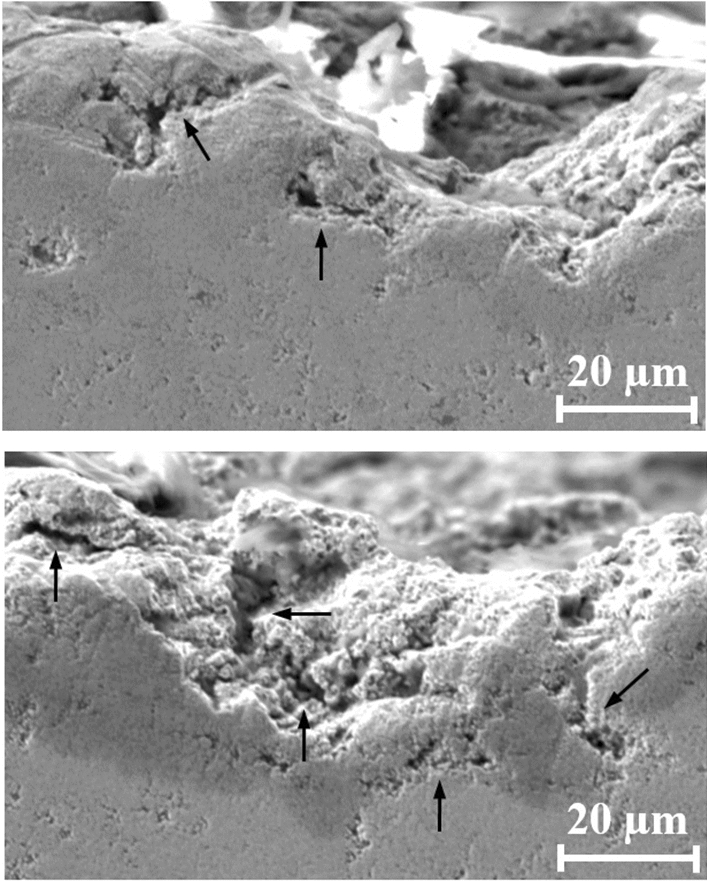
SEM cross-sectional micrographs of the eroded WC-CoCr coating after 330 min of exposure to cavitation: longitudinal and transverse cracks beneath of the coating surface
Fig. 9.
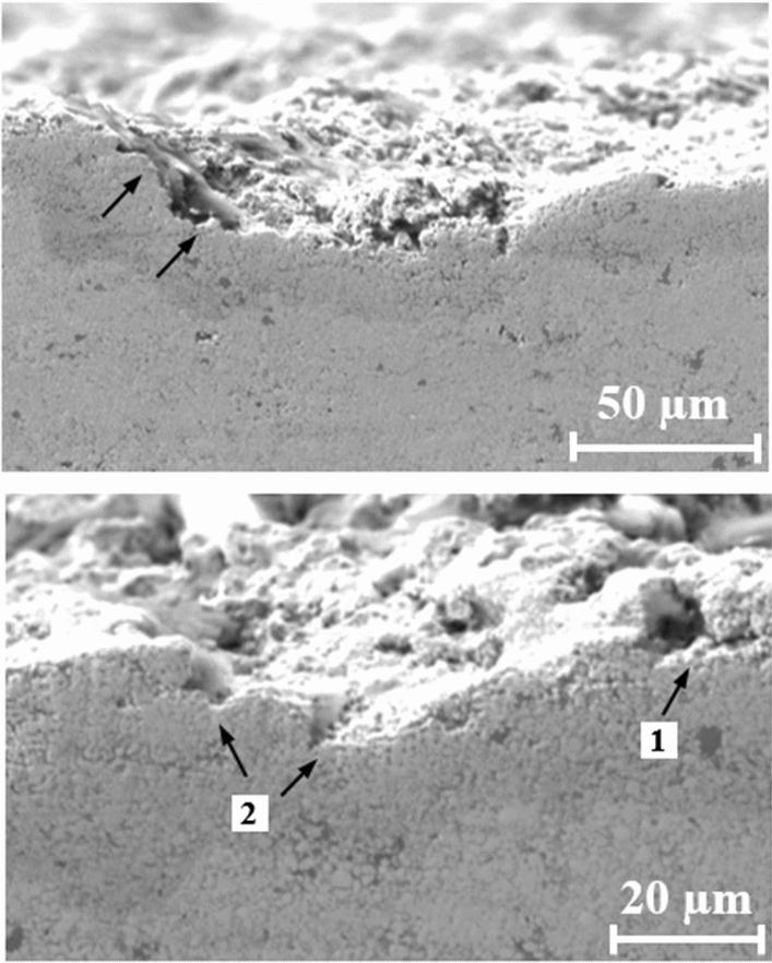
SEM cross-sectional micrographs of the eroded WC-CrC-Ni coating after 330 min of exposure to cavitation: development of cracks along “matrix-WC particles” boundary
Regarding the WC-CrC-Ni coating layer surface, the damaged area is 2-3 times smaller, and the pits are smaller by an order of magnitude. It can be observed that the development of cracks occurs along “matrix-WC particles” boundary. This is confirmed by the angular shape of the trajectory of the fractured surface (marked by arrows (Fig. 9a)). The defects in the coatings act as powerful sites of crack propagation (marked by arrow-1, (Fig. 9b)). Furthermore, when the developed microcracks connect together (marked by arrow-2, (Fig. 9b)), the detachment of the coating surface particles occurs.
According to studies of solid superalloys (Ref 69, 70), it can also be assumed that the increased corrosion resistance of the Ni-Cr matrix also lessened the cavitation damage of the coating, but this should be the subject of further research.
Conclusions
The cavitation tests in weakly alkaline environment revealed that volume loss of the WC-CoCr coating was greater than that of the WC-CrC-Ni coating. The study of the structure, phase composition, and surface topography was combined with the analysis of the results of third-party studies. They showed that the reasons for the lower susceptibility of WC-CrC-Ni coating to erosion cavitation damage comparing to WC-CoCr coating are as follows:
A finer structure and lower porosity, which leads to the reduction in material loss of this coating and, consequently, reduced cavitation damage;
The lower average values of roughness parameters of the WC-CrC-Ni coating’s surface;
In case of the WC-CrC-Ni coating, the hardening of the matrix due to the dissolution of Cr is combined with an increased plasticity of the matrix base. It helps to prevent chipping of the carbides from the matrix.
The combination of Cr and Ni in the WC-CrCNi coating results in improved corrosion resistance. As in the previous paragraph, it helps to prevent chipping of the carbides from the matrix.
Acknowledgments
The work was completed within state assignments from FASO Russia for IMP UB RAS on the subjects No. AAAA-A18-118020190116-6, № AAAA-A19-119070490049-8 and for IES UB RAS on the subject No. AAAA-A18-118020790147-4. The present study was supported by project № IRA-SME-66316 cladHEA+ (M-ERA.NET Call 2019-II) and M-ERA.Net ETAG18012 DuraCer. The experimental research was carried out using the equipment of the Plastometriya Collective Use Center of IES UB RAS.
Footnotes
This article is an invited paper selected from presentations at the 2021 International Thermal Spray Conference, ITSC2021, that was held virtually May 25-28, 2021 due to travel restrictions related to the coronavirus (COVID-19) pandemic. It has been expanded from the original presentation.
Publisher's Note
Springer Nature remains neutral with regard to jurisdictional claims in published maps and institutional affiliations.
References
- 1.R. Singh, S.K. Tiwari and S.K. Mishra, Cavitation Erosion in Hydraulic Turbine Components and Mitigation by Coatings: Current Status and Future Needs, J. Mater. Eng. Perform., 2012, 21(7), p 1539–1551. [Google Scholar]
- 2.C.E. Brennen, Cavitation and Bubble Dynamics, Oxford University Press, Oxford, 1995, p 80 [Google Scholar]
- 3.A. Karimi and J.L. Martin, Cavitation Erosion of Materials, Int. Met. Rev., 1986, 31(1), p 1–26. [Google Scholar]
- 4.Y.K. Zhou, J.G. He and F.G. Hammitt, Cavitation Erosion of Diesel Engine Wet Cylinder Liners, Wear, 1982, 76(3), p 321–328. [Google Scholar]
- 5.M. Dular, O.C. Delgosha and M. Petkovšek, Observations of Cavitation Erosion Pit Formation, Ultrason. Sonochem., 2013, 20(4), p 113–1120. [DOI] [PubMed] [Google Scholar]
- 6.J.F. Santa, L.A. Espitia, J.A. Blanco, S.A. Romo and A. Toro, Slurry and Cavitation Erosion Resistance of Thermal Spray Coatings, Wear, 2009, 267(1–4), p 160–167. [Google Scholar]
- 7.C.F. Naudé and A.T. Ellis, On the Mechanism of Cavitation Damage by Non hemispherical Cavities Collapsing in Contact with a Solid Boundary, J. Basic Eng. Trans. ASME, 1961, 83(4), p 648–656. [Google Scholar]
- 8.S. Hattori and N. Mikami, Cavitation Erosion Resistance of Stellite Alloy Weld Overlays, Wear, 2009, 267(11), p 1954–1960. [Google Scholar]
- 9.J.F. Santa, J.A. Blanco, J.E. Giraldo and A. Toro, Cavitation Erosion of Martensitic and Austenitic Stainless Steel Welded Coatings, Wear, 2011, 271(9–10), p 1445–1453. [Google Scholar]
- 10.M. Duraiselvam, R. Galun, V. Wesling, B.L. Mordike, R. Reiter and J. Oligmüller, Cavitation Erosion Resistance of AISI 420 Martensitic Stainless Steel Laser-Clad with Nickel Aluminide Intermetallic Composites and Matrix Composites with TiC Reinforcement, Surf. Coat. Technol., 2006, 201(3–4), p 1289–1295. [Google Scholar]
- 11.E.A. Brujan, T. Ikedab and Y. Matsumoto, Shock Wave Emission from a Cloud of Bubbles, Soft Matter, 2012, 8(21), p 5777–5783. [Google Scholar]
- 12.W. Lauterborn and H. Bolle, Experimental Investigation of Cavitation Bubble Collapse in the Neighborhood of a Solid Boundary, J. Fluid Mech., 1975, 72(2), p 391–399. [Google Scholar]
- 13.M.S. Plesset and R.B. Chapman, Collapse of an Initially Spherical Vapor Cavity in the Neighborhood of a Solid Boundary, J. Fluid Mech., 1971, 47(2), p 283–290. [Google Scholar]
- 14.M. Dular, B. Bachert, B. Stoffel and B. Širok, Relationship Between Cavitation Structures and Cavitation Damage, Wear, 2004, 257(11), p 1176–1184. [Google Scholar]
- 15.D. Toma, W. Brandl and G. Marginean, Wear and Corrosion Behaviour of Thermally Sprayed Cermet Coatings, Surf. Coat. Technol., 2001, 138(2–3), p 149–158. [Google Scholar]
- 16.L.M. Berger, P. Ettmayer, P. Vuoristo, T. Mäntylä and W. Kunert, Microstructure and Properties of WC-10%Co-4% Cr Spray Powders and Coatings: Part 1. Powder Characterization, J. Therm. Spray Technol., 2000, 10(2), p 311–325. [Google Scholar]
- 17.M. Factor and I. Roman, Use of Microhardness as a Simple Means of Estimating Relative Wear Resistance of Carbide Thermal Spray Coatings: Part 2. Wear Resistance of Cemented Carbide Coatings, J. Therm. Spray Technol., 2002, 11(4), p 482–495. [Google Scholar]
- 18.C. Lyphout, K. Sato, S. Houdkova, E. Smazalova, L. Lusvarghi, G. Bolelli and P. Sassatelli, Tribological Properties of Hard Metal Coatings Sprayed by High-Velocity Air Fuel Process, J. Therm. Spray Technol., 2016, 25(1–2), p 311–345. [Google Scholar]
- 19.C. Lyphout and S. Björklund, Internal Diameter HVAF Spraying for Wear and Corrosion Applications, Therm. Spray Technol., 2015, 24(1–2), p 235–243. [Google Scholar]
- 20.S.F. Wayne and S. Sampath, Structure/Property Relationships in Sintered and Thermally Sprayed WC-Co, J. Therm. Spray Technol., 1992, 1(4), p 307–315. [Google Scholar]
- 21.R. Schwetzke and H. Kreye, Microstructure and Properties of Tungsten Carbide Coatings Sprayed with Various High-Velocity Oxygen Fuel Spray Systems, J. Therm. Spray Technol., 1999, 8(3), p 433–439. [Google Scholar]
- 22.P.S. Babu, Y. Madhavi, L.R. Krishna, D.S. Rao and G. Padmanabham, Thermally-Sprayed WC-Based Cermet Coatings for Corrosion Resistance Applications, JOM, 2018, 70, p 2636–2649. [Google Scholar]
- 23.Q. Wang, Z. Tang and L. Cha, Cavitation and Sand Slurry Erosion Resistances of WC-10Co-4Cr Coatings, J. Mater. Eng. Perform., 2015, 24(6), p 2435–2443. [Google Scholar]
- 24.R.K. Kumar, M. Kamaraj, S. Seetharamu, T. Pramod and P. Sampathkumaran, Effect of Spray Particle Velocity on Cavitation Erosion Resistance Characteristics of HVOF and HVAF Processed 86WC-10Co4Cr Hydro Turbine Coatings, J. Therm. Spray Technol., 2016, 25(6), p 1217–1230. [Google Scholar]
- 25.S. Hong, Y. Wua, J. Zhang, Y. Zheng, Y. Zheng and J. Lin, Synergistic Effect of Ultrasonic Cavitation Erosion and Corrosion of WC–CoCr and FeCrSiBMn Coatings Prepared by HVOF Spraying, Ultrason. Sonochem., 2016, 31, p 563–569. [DOI] [PubMed] [Google Scholar]
- 26.H. Zhang, Y. Gong, X. Chen, A. McDonald and H. Li, A Comparative Study of Cavitation Erosion Resistance of Several HVOF-Sprayed Coatings in Deionized Water and Artificial Seawater, J. Therm. Spray Technol., 2019, 28, p 1060–1071. [Google Scholar]
- 27.X. Ding, Y. Huang, C. Yuan and Z. Ding, Deposition and Cavitation Erosion Behavior of Multimodal WC-10Co4Cr Coatings Sprayed by HVOF, Surf. Coat. Technol., 2020, 392, p 125757. [Google Scholar]
- 28.J. Liu, T. Chen, C. Yuan and X. Bai, Performance Analysis of Cavitation Erosion Resistance and Corrosion Behavior of HVOF-Sprayed WC-10Co-4Cr, WC-12Co, and Cr3C2-NiCr Coatings, J. Therm. Spray Technol., 2020, 29, p 798–810. [Google Scholar]
- 29.L.-M. Berger, Binary WC– and Cr3C2–Containing Hardmetal Compositions for Thermally Sprayed Coatings, IOP Conf. Ser. Mater. Sci. Eng., 2016, 118(1), p 1–8. [Google Scholar]
- 30.Z. Ding, Y. Zhang and H. Zhao, Resistance of HVOF nanostructured WC-12Co Coatings to cavitation erosion, Thermal Spray 2007: Global Coating Solutions, Vol 1. B.R. Marple et al., Ed., . ASM International, . Materials Park, Ohio, USA, 2007, p 633–637 [Google Scholar]
- 31.G. Hou, X. Zaho, H. Zhou and J. Lu, Cavitation Erosion of Several Oxy-Fuel Sprayed Coatings Tested in Deionized Water and Artificial Seawater, Wear, 2014, 311(1–2), p 81–92. [Google Scholar]
- 32.V.A.D. Souza and A. Neville, Linking Electrochemical Corrosion Behaviour and Corrosion Mechanisms of Thermal Spray Cermet Coatings (WC-CrNi and WC/CrC-CoCr), Mater. Sci. Eng. A, 2003, 352(1–2), p 202–211. [Google Scholar]
- 33.X. Ding, X.-D. Cheng, C.-Q. Yuan, J. Shi and Z.-X. Ding, Structure of Micro-nano WC-10Co4Cr Coating and Cavitation Erosion Resistance in NaCl Solution, Chin. J. Mech. Eng., 2017, 30, p 1239–1247. [Google Scholar]
- 34.N. Espallargas, J. Berget, J.M. Guilemany, A.V. Benedetti and P.H. Suegama, Cr3C2–NiCr and WC–Ni Thermal Spray Coatings as Alternatives to Hard Chromium for Erosion-Corrosion Resistance, Surf. Coat. Technol., 2008, 202(8), p 1405–1417. [Google Scholar]
- 35.V.A.D. Souza and A. Neville, Corrosion and Synergy in a WC Co Cr HVOF Thermal Spray Coating—Understanding their Role in Erosion–Corrosion Degradation, Wear, 2005, 259(1–6), p 171–180. [Google Scholar]
- 36.G. Bolelli, L.-M. Berger, M. Bonetti and L. Lusvarghi, Comparative Study of the Dry Sliding Wear Behaviour of HVOF-Sprayed WC–(W, Cr)2C–Ni and WC–CoCr Hard Metal Coatings, Wear, 2014, 309, p 96–111. [Google Scholar]
- 37.B. Song, J.W. Murray, R.G. Wellman, Z. Pala and T. Hussain, Dry Sliding Wear Behaviour of HVOF Thermal Sprayed WC-Co-Cr and WC-CrxCy-Ni Coatings, Wear, 2020, 442–443, p 203114. [Google Scholar]
- 38.A. Kanno, K. Takagi and M. Arai, Influence of Chemical Composition, Grain Size, and Spray Condition on Cavitation Erosion Resistance of High-Velocity Oxygen Fuel Thermal-Sprayed WC Cermet Coatings, Surf. Coat. Technol., 2020, 394, p 125881. 10.1016/j.surfcoat.2020.125881 [Google Scholar]
- 39.S. Kuroda, M. Watanabe, K. Kim and H. Katanoda, Current Status and Future Prospects of Warm Spray Technology, J. Therm. Spray Technol., 2011, 20(4), p 653–676. [Google Scholar]
- 40.Yu.S. Korobov, Comparative Analysis of Supersonic Gas-Flame Methods of Coating Application, Metallurgist, 2006, 50(3–4), p 158–162. [Google Scholar]
- 41.G. Bolelli, L.-M. Berger, T. Börner, H. Koivuluoto, L. Lusvarghi, C. Lyphout, N. Markocsan, V. Matikainen, P. Nylén, P. Sassatelli, R. Trache and P. Vuoristo, Tribology of HVOF- and HVAF-Sprayed WC–10Co4Cr Hardmetal Coatings: A Comparative Assessment, Surf. Coat. Technol., 2015, 265, p 125–144. [Google Scholar]
- 42.I. Hulka, D. Utu, V.A. Serban, M. Dan, V. Matikainen and P. Vuoristo, Corrosion Behavior of WC-Ni Coatings Deposited by Different Thermal Spraying Methods, Chem. Bull. Politeh. Univ. (Timisoara), 2015, 60(2), p 60–65. [Google Scholar]
- 43.V. Matikainen, H. Koivuluoto, P. Vuoristo, J. Schubert and S. Houdkova, Effect of Nozzle Geometry on the Microstructure and Properties of HVAF-Sprayed WC-10Co4Cr and Cr3C2-25NiCr Coatings, J. Therm. Spray Technol., 2018, 27(4), p 680–694. [Google Scholar]
- 44.Metallic and oxide coatings – Measurement of coating thickness – Microscopical method, ISO 1463, 2003.
- 45.Standard Test Method for Cavitation Erosion Using Vibratory Apparatus, G32-10, ASTM, 2011, p 1–19.
- 46.V.I. Shumyakov, Yu.S. Korobov, H.L. Alwan, N.V. Lezhnin, A.V. Makarov, M.S. Deviatiarov, Installation for Cavitation Erosion Test, Patent, No. 2710480, 2019 (in Russian).
- 47.A.R. Mayer, K. Bertuol, I.B.A.F. Siqueira, A. Chicoski, R.F. Váz, M.J. de Sousa and A.G.M. Pukasiewicz, Evaluation of cavitation/corrosion synergy of the Cr3C2-25NiCr coating deposited by HVOF process, Ultrason. Sonochem., 2020, 69, p 105271. [DOI] [PubMed] [Google Scholar]
- 48.Q.N. Song, Y. Tong, N. Xu, S.Y. Sun, H.L. Li, Y.F. Bao, Y.F. Jiang, Z.B. Wang and Y.X. Qiao, Synergistic Effect Between Cavitation Erosion and Corrosion for Various Copper Alloys in Sulphide-Containing 3.5% NaCl solutions, Wear, 2020, 450–451, p 203258. [Google Scholar]
- 49.P.M. Polivanov, and E.P. Polivanova. Tables for calculating the mass of parts and materials: Handbook. 13th edition, 2006 (In Russian).
- 50.Test Methods for Determining Area Percentage Porosity in Thermal Sprayed Coatings, ASTM E 2119, 2002.
- 51.Geometrical Product Specifications (GPS) - Surface texture: Profile method - Terms, definitions and surface texture parameters, ISO 4287, 1997.
- 52.L.-M. Berger, R. Trache, F.-L. Toma, S. Thiele, J. Norpoth and L. Janka, Development of Cost-Effective Hardmetal Coating Solutions for High-Temperature Applications, Part One: Feedstock Powders, Cost-Effectiveness and Coating Properties, Therm. Spray Bull., 2015, 8(2), p 126–136. [Google Scholar]
- 53.DSMTS-0113.7 – WC 10Co 4Cr Sintered and Crushed Powders, Material Product Data Sheet, Oerlikon Metco, 2017, p 3.
- 54.X.T. Luo, R.C. Seshadri and G.J. Yang, Micro-nanostructured cermet coatings, Adv. Nanomater. Coat. Therm. Spray, 2019 10.1016/B978-0-12-813870-0.00004-8 [Google Scholar]
- 55.D. Kekes, P. Psyllaki and M. Vardavoulias, Wear Micro-Mechanisms of Composite WC-Co/Cr - NiCrFeBSiC Coatings. Part I: Dry Sliding, Tribol. Ind., 2014, 36(4), p 361–374. [Google Scholar]
- 56.M. Vostřák, Š Houdková, M. Bystrianský and Z. Česánek, The Influence of Process Parameters on Structure and Abrasive Wear Resistance of Laser Clad WC-NiCrBSi Coatings, Mater. Res. Express, 2018, 5(9), p 096522. [Google Scholar]
- 57.J.E. Cho, S.Y. Hwang and K.Y. Kim, Corrosion Behavior of Thermal Sprayed WC Cermet Coatings Having Various Metallic Binders in Strong Acidic Environment, Surf. Coatings Technol., 2006, 200, p 2653–2662. [Google Scholar]
- 58.Y. Wu, S. Hong, J. Zhang, Z. He, W. Guo, Q. Wang and G. Li, Microstructure and Cavitation Erosion Behavior of WC–Co–Cr Coating on 1Cr18Ni9Ti Stainless Steel by HVOF Thermal Spraying, Int. J Refract. Met. H, 2012, 32, p 21–26. [Google Scholar]
- 59.F.-W. Bach, A. Laarmann and T. Wenz, Modern Surface Technology, Wiley-VCH Verlag GmbH & Co. KGaA, Weinheim, 2006, p 338 [Google Scholar]
- 60.M. Jalali Azizpour and M. Tolouei-Rad, The Effect of Spraying Temperature on the Corrosion and Wear Behavior of HVOF Thermal Sprayed WC-Co Coatings, Ceram. Int., 2019, 45, p 13934–13941. [Google Scholar]
- 61.J.A. Picas, M. Punset, E. Rupérez, S. Menargues, E. Martin and M.T. Baile, Corrosion Mechanism of HVOF Thermal Sprayed WC-CoCr Coatings in Acidic Chloride Media, Surf. Coat. Technol., 2019, 371, p 378–388. [Google Scholar]
- 62.Q. Wang, S. Zhang, Y. Cheng, J. Xiang, X. Zhao and G. Yang, Wear and Corrosion Performance of WC-10Co4Cr Coatings Deposited by Different HVOF and HVAF Spraying Processes, Surf. Coat. Technol., 2013, 218, p 127–136. [Google Scholar]
- 63.P.S. Babu, B. Basu and G. Sundararajan, Processing–Structure–Property Correlation and Decarburization Phenomenon in Detonation Sprayed WC–12Co Coatings, Acta Mater., 2008, 56, p 5012–5026. [Google Scholar]
- 64.P.B. Kenway, and P.J. Duke, X-ray Optics and Microanalysis 1992. In: Proceedings of the 13th INT Conference, 31 August-4 September 1992, Inst. Phys. Conf. Ser. No. 130, Manchester, UK, p 1-680.
- 65.C. Guo, J. Zhou, J. Chen, J. Zhao, Y. Yu and H. Zhou, High Temperature Wear Resistance of Laser Cladding NiCrBSi and NiCrBSi/WC-Ni Composite Coatings, Wear, 2011, 270, p 492–498. [Google Scholar]
- 66.K.-H. Shi, K.-C. Zhou, Z.-Y. Li, D. Zhang and X.-Q. Zan, Microstructure and Formation Process of Ni-Pool Defect in WC−8Ni Cemented Carbides, Trans. Nonferrous Met. Soc. China, 2015, 25, p 873–878. [Google Scholar]
- 67.L.-M. Berger, Application of Hardmetals as Thermal Spray Coatings, Int. J. Refract Met. H, 2015, 49, p 350–364. [Google Scholar]
- 68.L.-M. Berger, S. Saaro, T. Naumann, M. Kasparova and F. Zahalka, Influence of Feedstock Powder Characteristics and Spray Processes on Microstructure and Properties of WC-(W, Cr)2C-Ni Hardmetal coatings, Surf. Coat. Technol., 2010, 205, p 1080–1087. [Google Scholar]
- 69.B. Cheniti, D. Miroud, P. Hvizdoš, J. Balko, R. Sedlák, T. Csanádi, B. Belkessa and M. Fides, Investigation of WC Decarburization Effect on the Microstructure and Wear Behavior of WC-Ni Hardfacing Under dry and Alkaline Wet Conditions, Mater. Chem. Phys., 2018, 208, p 237–247. [Google Scholar]
- 70.L.L. Zhukov, I.M. Plemyannokova, M.N. Mironova, D.S. Barkaya, and Yu.V. Shumkov, Alloys for heaters, Metallurgy, Moscow, 1985, p 144 (in Russian).
- 71.V.A. Pugsley and C. Allen, Microstructurer/Property Relationships in the Cavitation Erosion of Tungsten Carbide–Cobalt, Wear, 1999, 233–235, p 93–103. [Google Scholar]
- 72.G. Bregliozzi, A. Di Schino, S.I.-U. Ahmed, J.M. Kenny and H. Haefke, Cavitation Wear Behaviour of Austenitic Stainless Steels with Different Grain Sizes, Wear, 2005, 258(1–4), p 503–510. [Google Scholar]
- 73.K. Sugiyama, S. Nakahama, S. Hattori and K. Nakano, Slurry Wear and Cavitation Erosion of Thermal-Sprayed Cermets, Wear, 2005, 258, p 768–775. [Google Scholar]
- 74.G.V. Samsonov and G.M. Vinitsky, Handbook of Refractory Compounds, Metallurgy, Moscow, 1976, p 560 (in Russian).
- 75.R. Warren and M.B. Waldron, Microstructural development during liquid-phase sintering of cemented carbides. I. Wettability and grain contact, Powder Metall., 1972, 15(30), p 166–201. [Google Scholar]
- 76.A.B. Straumal, Complete, incomplete and pseudo-incomplete wetting of grain’s boundaries of solid and liquid phases, Thesis for the degree of Candidate of Science, MISIS, Moscow, 2017, p 115 (in Russian).
- 77.A.V. Bobylev, Mechanical and Technological Properties of Metals: Handbook, Metallurgy, Moscow, 1987, p 208 (in Russian).