

Abstract
Phenyltelluroxane clusters of the composition [{(PhTe)19O24}2I18(solv)] (1) are formed during the hydrolysis of [PhTeI3]2 or the oxidation of various phenyltellurium(II) compounds with iodine under hydrolytic conditions. The compounds consist of two half‐spheres with a {(PhTe)19O24}9+ network, which are connected by 18 iodine atoms. The spherical clusters can accommodate solvent molecules such as pyridine or methanol in the center of two rings formed by iodine atoms. The presence of other metal ions during the cluster formation results in a selective replacement of the central {PhTe}3+ units of each half‐sphere as has been demonstrated with the isolation of [{(PhTe)18({Ca(H2O)2}O24}2I16] (2) and [{(PhTe)18({Y(NO3)(H2O)}O24}2I16] (3). A crownether‐like coordination by six oxygen atoms of the telluroxane network is found for the {Ca(H2O}2}2+ and {Y(NO3)(H2O)}2+ building blocks. Mass spectrometric studies show that considerable amounts of the intact clusters are transferred to the gas phase without dissociation.
Keywords: clusters, mass spectrometry, tellurium, telluroxanes, X-ray diffraction
Large telluroxane clusters are formed during the hydrolysis of [PhTeI3]2 or the oxidation of [PhTe]2 with iodine under hydrolytic conditions. They consist of two half‐spheres with {(PhTe)19O24}9+ networks, which are connected by 18 iodine atoms. The central {PhTe}3+ units of each half‐sphere can be replaced by other metal ions. Mass spectrometry shows that the intact clusters are transferred to the gas phase without dissociation.
Introduction
Organotellurium oxides or telluroxanes represent a class of compounds, which has attracted an increasing interest during the recent years. Two excellent reviews comprise synthetic routes, general structural patterns and applications of this class of compounds having at least one covalent tellurium‐oxygen bond.[1, 2] But these recent summaries make also obvious that hitherto relatively little is known about the structural chemistry particularly of larger telluroxanes. Telluroxanes are commonly prepared by hydrolysis of organotellurium(IV) halides and a strict control of the reaction conditions is required for the preparation of defined molecular products and to avoid polymerization. This means that frequently starting materials with sterically hindered organic residues or additional oxygen or nitrogen donor atoms have been used. Following such an approach, well defined dimeric, trimeric, hexameric, heptameric or octameric units have been isolated and characterized by crystallography.[2, 3, 4, 5, 6, 7, 8] Some examples are shown in Scheme 1.
Scheme 1.

Examples of well‐defined molecular telluroxanes stabilized by bulky substituents or additional donor atoms.[3, 5, 6, 7, 10]
Two larger, well‐defined telluroxanes comprising twelve and nineteen tellurium atoms have been serendipitously obtained from unintended reactions. The anionic cluster compound [{(iPrTe)12O16Br4{Li(THF)Br}4}Br]− is formed by a reaction of lithium hex‐1‐ynyl tellurolate with isopropyl bromide in THF by partial air oxidation and hydrolysis,[9] while a bowl‐shaped cluster described as [(PhTe)19O24Br5]4+ is formed by the disproportionation of the selone adduct [(1,3‐dibutylbenzimidazolin‐2‐selone)TePh](PhTeBr2) in acetonitrile with subsequent hydrolysis.[10] Even when the used starting materials and the intended reactions applied for the formation of the two large tellurium clusters are completely different, there is a striking similarity: both mixtures finally contain organotellurium(IV) bromides and traces of water as a starting point for a controlled hydrolysis and the self‐assembly of defined, charged {TeIV xOy} networks, and they contain bromide ions, which seem to play a role in the stabilization of the established 3‐dimensional structures. A third example of such reactions, the accidental formation of the spherical compound [{(PhTe)19O24}2I18(pyridine)] (1 a) from a reaction of N‐{3‐(phenyltellanyl)propyl}picolinamide (I) with elemental iodine in CH2Cl2,[11] lead us to more detailed studies about the essential compounds and a rational synthetic approach to such clusters (Scheme 2).
Scheme 2.

Formation of the [{(PhTe)19O24}2I18] telluroxane clusters.
Results and Discussion
In the context of our studies on transition metal complexes with tellurium‐containing ligands,[12, 13, 14, 15] we synthesized some telluroethers such as N‐{3‐(phenyltellanyl)propyl}picolinamide (I) or 3‐(phenyltellanyl)propylamine (II) as building blocks for chelating ligands. The oxidation of compound I with elemental iodine did not yield the expected tellurium(IV) diiodide, but gave a red‐brown, crystalline substance of the composition [{(PhTe)19O24}2I18(pyridine)] (1 a). Single crystals of the product were obtained from a CH2Cl2/CHCl3/MeOH (3:8:3) mixture. They consist of large, spherical clusters with an almost planar layer of eighteen iodine atoms between two half‐shells each composed from a {(PhTe)19O24}9+ network (Figure 1). The phenyltellurium units of the {(PhTe)19O24}9+ subunits establish two concentric oxygen‐bridged ring systems comprising twelve and six {PhTe}3+ building blocks with the remaining subunit in its center. Also the iodine atoms are arranged in two rings comprising twelve and six members, respectively.
Figure 1.

a) Structure of 1 a (the central pyridine ring is omitted for clarity) and b) top‐view to one {(PhTe)19O24}9+ half‐shell of 1 a with the central layer of iodine atoms and the central pyridine ring.[36]
The iodine atoms of the outer ring establish electrostatic interactions with the tellurium atoms of the outer ring systems of both half‐shells. Te−I distances between 3.093 and 3.795 Å are found between the iodine atoms I1 to I12 and their adjacent tellurium atoms in both half spheres, which corresponds to “normalized contacts” NC of 0.76 and 0.94 (NC =DTeI/(rTe + rI), DTeI is the experimentally determined distance between the tellurium and iodine atoms and rTe and rI correspond to the van der Waals radii of the elements). NC is a useful indicator to estimate the strength of contacts in compounds with “long‐range interactions” and has been applied for the evaluation of compounds with halogen bonds by Metrangolo and Resnati.[16] Unlike the absolute values of the bond lengths, this parameter allows a direct comparison between “long‐range” interactions with donor‐acceptor pairs. This means for the compounds under study that the bonding forces for the “outer‐sphere” Te−I bonds are in the magnitude of those of the iodine atoms in the triiodide ions in (Me3NC6H12NMe3)I3.[17] But also many Te−I bonds fall into this range, for example, those in [PhTeI3]2, [TeI(thiourea)]2 or [Me2PhTeI]2.[18, 19, 20, 21] Due to the spherical structure of the cluster, the distances of the inner, six‐membered ring of iodine atoms to their adjacent tellurium atoms are clearly longer (3.808–4.150 Å), but most of them are still within the sum of the van der Waals radii of tellurium and iodine.[22] DFT calculations confirm the mainly electrostatic nature of these interactions. Average energies of −13 kJ mol−1 (Te–Iouter ring) and −8 kJ mol−1 (Te–Iinner ring) have been derived for the tellurium‐iodine interactions. Additionally, some hydrogen bonds between ortho H atoms of outer‐sphere phenyl rings and iodine atoms support the formation of the cluster. They are evident from a detailed inspection of the solid‐state structures, but are also reflected by the appearance of bond critical points in the DFT calculations. Details are discussed in the Supporting information.
The center of the sphere of compound 1 a is occupied by a molecule of pyridine. It clearly comes from the decomposition of the starting material I and is located in the center of the inner ring of iodine atoms. Hydrogen bonds are established between the pyridine and the inner ring of iodine atoms (Figure 1 b), which allows the unambiguous assignment of the nitrogen atom since the detected N⋅⋅⋅I distance is clearly longer than the C(H)⋅⋅⋅I ones. It is interesting to note that the incorporation of pyridine into the spheres of [{(PhTe)19O24}2I18] only succeeds when the cluster is prepared by the decomposition of I. All our attempts to prepare 1 a via the more rational approaches starting from [PhTeI]4 or [PhTeI3]2 (vide infra) with the addition of small amounts of pyridine only resulted in co‐crystallization of the solvent in the voids between the large clusters.
With respect to the ready and reproducible formation of 1 a from the telluroether I, it is not surprising that a similar reaction of 3‐(phenyltellanyl)propylamine (II) with iodine results in the related cluster 1 b. All basic structural features discussed above for 1 a also apply for 1 b, with the exception that of course no pyridine is embedded in the central layer of iodine atoms.
It is evident that the synthesis of such large, but well‐defined cluster compounds from less defined degradation reactions of particular organotellurium compounds is not satisfactory. Thus, we tested more rational and reliable approaches to the compounds of type 1. Having in mind that for the assembly of the {(PhTe)19O24}9+ half‐shells only {PhTe}3+ building blocks and water are required, we performed reactions starting from diphenylditelluride with water and different amounts of iodine. It is known that Ph2Te2 reacts with one equivalent of I2 under formation of [PhTeI]4,[23, 24] while a similar reaction with three equivalents of iodine gives [PhTeI3]2.[18] The subsequent addition of water (and in the case of [PhTeI]4 exposure to air) gave the clusters 1 as red‐brown crystalline solids. It turned out that the direct hydrolysis of previously isolated (or by the oxidation of diphenyl ditelluride with 3 equivalents of I2 in situ‐produced) [PhTeI3]2 is less favorable. It forms the cluster compounds 1 b and 1 c, but with a number of side‐products and the required purification operations lower the yields. Best results and yields of about 50 % of the pure clusters are obtained, when diphenyl ditelluride is reacted with only one equivalent iodine and the in situ‐produced [PhTeI]4 is subsequently heated in a CH2Cl2/MeOH/H2O mixture on air. Pure crystalline products of 1 b and 1 c are obtained, when the obtained red‐brown solid is crystallized from a CH2Cl2/CHCl3/MeOH (3:8:3) mixture. The incorporation of MeOH in the void between the iodine atoms is observed when the reaction is performed in MeOH/H2O without the addition of CH2Cl2.
As in the cluster 1 a, iodine‐tellurium interactions and hydrogen bonds connect the two half‐spheres of 1 b and 1 c.
To prove the existence of the cluster after dissolving in CH2Cl2 and the ionization process, the [{(PhTe)19O24}2I18] cluster (1 b) was studied by ESI mass spectrometry. Ions of the intact [{(PhTe)19O24}2I18] cluster are present in a CH2Cl2 solution of the compound and are transferred into the gas phase without decomposition.
The (+)‐ESI mass spectrum is dominated by a peak group with a charge state of +3 with an m/z range of approximately 3400 to 3520, showing the [M−3 I]3+ ion as the major peak. Not only the organic residues, but mainly the 38 tellurium atoms of the two half‐shells lead to a theoretical isotopic pattern with more than 80 single peaks of significant abundance (>1 %). This results in an impressively peak‐rich mass spectrum. Figure 2 shows the “+3” charge state region of the spectrum and the assignment of the peaks as well as a comparison with calculated isotopic patterns is summarized in Table 1. The situation is complicated by the fact that a few I− ions are exchanged by Br− (presumably coming from a minor impurity of the used I2) or Cl− (abstracted from the solvents used). Up to three exchanges in total, max. 2 exchanges for Br− and max. one for Cl− are observed. A second group of peaks of slightly lower abundance is found between m/z 5150 and 5350, showing the [M−2 I]2+ ion and the derivatives formed by exchange of I− by Br− or Cl− (see Supporting information). In both charge states, addition of CH2Cl2 can be observed, presumably located in the inner void of the cluster.
Figure 2.

ESI‐MS spectrum of the “+3” charge state region of 1 b. Black: experimental data, red: simulations.[26] For assignment see Table 1.
Table 1.
Comparison of the experimental and calculated isotopic patterns of the “+3” ion region in the mass spectra of 1 b.
|
Ion |
Chemical Formula |
m/zexp |
m/zcalc |
Δ m/z [ppm] |
|---|---|---|---|---|
|
[M−3 I]3+ |
(C228H190O48I15Te38)3+ |
3483.703 |
3483.733 |
8.6 |
|
[M−4 I+Br]3+ |
(C228H190O48I14Te38Br)3+ |
3467.721 |
3467.737 |
4.6 |
|
[M−4 I+Cl]3+ |
(C228H190O48I14Te38Cl)3+ |
3453.421 |
3453.393 |
8.1 |
|
[M−5 I+2 Br]3+ |
(C228H190O48I13Te38Br2)3+ |
3452.408 |
3452.367 |
11.9 |
|
[M−5 I+Br+Cl]3+ |
(C228H190O48I13Te38BrCl)3+ |
3437.425 |
3437.379 |
13.3 |
|
[M−6 I+2 Br+Cl]3+ |
(C228H190O48I12Te38Br2Cl)3+ |
3422.066 |
3422.096 |
8.8 |
|
[M−5 I+2 Cl]3+ |
(C228H190O48I13Te38Cl2)3+ |
3422.442 |
3422.398 |
12.8 |
|
[M−3 I+(CH2Cl2)]3+ |
(C229H192O48I15Te38Cl2)3+ |
3512.050 |
3511.998 |
14.8 |
|
[M−3 I+H+Br]3+ |
(C228H191O48I15Te38Br)3+ |
3510.679 |
3510.708 |
8.3 |
|
[M−4 I+Br+(CH2Cl2)]3+ |
(C229H192O48I14Te38BrCl2)3+ |
3495.693 |
3495.721 |
7.8 |
Another hint for the stability of the clusters 1 in solution is given with their NMR spectra. 1H spectra show the expected variety of aromatic protons in the range between 6.5 and 8.2 ppm due to the slightly varying environments of the PhTe groups inside the telluroxane network. All our attempts to measure well‐resolved 125Te NMR spectra failed. This comes not completely unexpected with regard to the limited solubility of the cluster compounds and the low natural abundance (≈7 %) and less favorable NMR properties of 125Te (≈0.2 % receptivity relative to 1H). A comparison with the behavior of the related bromide cluster [(PhTe)19O24Br5]4+, however, let us interpret this finding as another proof of the stability of the compounds 1 in solution. For [(PhTe)19O24Br5]Br4, one single, intense 125Te NMR signal has been observed at 1516 ppm, which has been described as a proof of the rapid decomposition of [(PhTe)19O24Br5]Br4 in solution.[10]
The obviously higher stability of the clusters 1 compared to the related bromide compound of ref. [10] is not related to the composition of the tellurium‐oxygen networks in both compounds. The arrangement of the tellurium atoms, the Te−O bond lengths and the connectivity patterns are almost identical in both compounds. Figure 3 shows the Te−O network of one half‐shell of cluster 1 b. It is evident that, with the exception of Te31, all tellurium atoms undergo additional bonding interactions with the atoms of the central layer of iodine atoms as has been discussed before for 1 a. The phenyltellurium unit of Te31 is bonded in the center of six oxygen atoms, the arrangement of which reminds of the crown ether 18‐crown‐6. The related Te−O distances vary within a large range (1.926(9)–3.343(9) Å), but their arrangement (two short, two medium and two long bonds) is similar to the situation in the only other crown‐ether complex with a TeIV ion, [(18‐crown‐6)Te(Cl)(μ‐O)2Te(Cl)(18‐crown‐6)][SbCl6]2, where the Te−O(crown ether) distances are 2.549/2.582, 2.651/2.751 and 2.886, 4.164 Å.[26]
Figure 3.

Te−O network of 1 b with designation of Te−I interactions with the central layer of iodine atoms. Dotted lines indicate Te−O (blue) and TeI (purple) interactions larger than 3.220 Å and 3.636 Å, respectively (90 % of the sum of the van der Waals radii). Solid lines represent shorter bonds.[36]
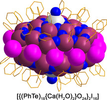
The unique bonding situation of the “PhTe31 groups” in the cluster is also reflected by its reactivity. Unlike all other phenyltellurium building blocks in compound 1 b, this central unit can be replaced by metal ions and, thus, “functionalized” telluroxane clusters can be formed. The introduction of Ca2+ ions in the central positions of the half‐shells is readily possible by exposing the (PhTe)2/I2/H2O reaction mixture to a Ca2+ source such as CaO. The color of the solution becomes brighter and finally colorless crystals of the composition [{(PhTe)18{Ca(H2O)2}O24}2I16] (2) can be isolated. The molecular structure of the compound is shown in Figure 4.
Figure 4.

a) Structure of 2 and b) top‐view to one {(PhTe)18{Ca(H2O)2}O24}8+ half‐shell with the central layer of iodine atoms (the atom I12 and its symmetry related positions possess an occupancy of 0.5.).[36]
Unlike the atom Te31 and its expression in the second half‐sphere in the compounds 1 a–1 c, which are non‐centrically embedded between the six oxygen atoms of the central ring (Figure 3), the Ca2+ ions in the [{(PhTe)18{Ca(H2O)2}O24}2I16] networks are located on a twofold axis and show very similar Ca−O bonds between 2.479(7) and 2.538(3) Å. These values are somewhat shorter than in 18‐crown‐6 complexes with Ca2+ ions (2.538–2.684 Å), where the metal ions are nine‐coordinate with three additional water ligands.[27, 28, 29, 30] The calcium ions in 2 are eight‐coordinate with only two axial H2O ligands in a hexagonal‐bipyramidal coordination environment. Due to the formal replacement of two {PhTe}3+ groups by two {Ca(H2O)2}2+ units, the charge of the cluster is reduced. Charge compensation is done by an only partial occupation of the positions of the iodine atoms of the inner ring (see Figure 4 b).
An unexpected feature of compound 2 is the fact that it is nearly colourless, particularly in contrast to the brown compounds of type 1 with a central PhTe3+ unit. DFT calculations show that main contributions within the near UV‐Visible/absorption region of both complexes can be attributed to charge‐transfer bands of iodine‐centered p‐orbitals into Te−O anti‐bonding or Te‐centered empty p‐orbitals. Both compounds show a large degree of delocalization in their HOMO and LUMO orbitals. The degree of delocalization of the ground state LUMO is similar in both compounds. However, the ground state HOMO of [{(PhTe)19O24}2I18] (1 b) is delocalized over the whole layer of iodine atoms. Contrarily, the HOMO of [{(PhTe)18{Ca(H2O)2}O24}2I16] (2) is rather concentrated on the outer iodide ring, while the LUMO is still centered on the inner telluroxane ring. The overall more prominent delocalization of the electron density in [{(PhTe)19O24}2I18] (1 b) results in smaller HOMO–LUMO gaps between the ground‐state and the excited states compared to [{(PhTe)18{Ca(H2O)2}O24}2I16] (2). Consequently, the HOMO and LUMO geometric arrangement and energy difference in 1 b are much more favorable for a charge transfer compared to [{(PhTe)18{Ca(H2O)2}O24}2I16] (2). This results in a shift of the corresponding absorption from the visible part of the spectrum into the near UV range, and can explain the fact that compound 2 appears almost colorless, while the compounds 1 with phenyltellurium‐centered half‐shells have a brownish color. More details are outlined in the Supporting Information.
All telluroxanes under study form highly porous structures with large voids between the cluster units. Figure 5 depicts the channel structure inside compound 2. The peripheral phenyl substituents enclose hydrophobic voids with a mean diameter of 7.4 Å. They are filled with diffuse solvent molecules. The remaining percentage of the voids is 11 % in 2. This is somewhat more than in the previously discussed [{(PhTe)19O24}2I18] compounds (approximately 9 %).[31]
Figure 5.

View along the crystallographic c‐axis of compound 2 depicting large hydrophobic voids between the cluster units.[36]
Mass spectrometric studies confirm that also the calcium modified telluroxane cluster is stable in solution and can be transferred into the gas phase. The regions of the “+3” and “+2” ions are dominated by the [{(PhTe)18{Ca(H2O)}O24}2I13]3+ (i.e. [M−3 I−2 H2O]3+) and [{(PhTe)18{Ca(H2O)}O24}2I14]2+ (i.e. [M−2 I−2 H2O]2+) ions as well as by the corresponding ions with one water molecule more or less and/or partial addition of the solvent used, CH2Cl2. This clearly shows that the integrity of the clusters is preserved after dissolving in dichloromethane and ionization by electrospray. Species with minor abundance can be attributed to an exchange of one I− ion by Cl− (coming from the solvent). More details are given in the Supporting Information.
The concept for the synthesis of compound 2 can be extended to other metal ions such as lanthanides or “group 3” elements. Addition of M3+ nitrates to the above described (PhTe)2/I2/H2O reaction mixture gives telluroxane clusters with two central {MIII(NO3)(H2O)}2+ units. Their aqua ligands point to the center of the cluster, while the bidentate bonded nitrato ligands are located in their outer sphere. Charge balance is done as in the case of compound 2 by the partial occupation of the central layer of iodine atoms giving a composition of [{(PhTe)18{MIII(NO3)(H2O)}O24}2I16].
Figure 6 illustrates the structure of [{(PhTe)18{Y(NO3)(H2O)}O24}2I16] (3) with two peripheral nitrato ligands. The Y3+ ions are nine‐coordinate with Y−O(network) bonds all being between 2.387(9) and 2.456(9) Å. These values perfectly fit with the corresponding Y−O(crown ether) bond lengths in [Y(Cl(H2O)2(18‐crown‐6)]2+.[32] But unlike the situation in the crown ether, the oxygen donors in 3 are embedded in the telluroxane networks. Thus, they form an almost planar hexagonal plane (maximum deviation from a mean‐least‐square plane: 0.056 Å). The Y3+ ion is situated 0.242 Å above this plane.
Figure 6.

Molecular structure of [{(PhTe)18{Y(NO3)(H2O)}O24}2I16] (3).[36]
As already described for the compounds 1 and 2, also the intact cluster [{(PhTe)18{Y(NO3)(H2O)}O24}2I16] is transferred to the gas phase during the mass spectrometric ionization procedure. The spectra are dominated by doubly charged ions with m/z values between 5100 and 5400. The following molecular compositions have been assigned with changing intensities: [M−2 I]2+, [M−I+H]2+, [M+2 H]2+. Additionally, corresponding complexes with up to two molecules of dioxane and/or CHCl3 are visible: [M−2 I+(C4H8O)]2+, [M−2 I+(C4H8O)2]2+, [M−I+H+(C4H8O)]2+, [M−I+H+(C4H8O)2]2+, [M+2 H+(C4H8O)]2+ and [M+2 H+(C4H8O)2]2+ as well as [M−3 I−H2O+Cl+CCl3H]2+, [M−3I+Cl+CCl3H]2+,. [M−2 I−H2O+CCl3H]2+, [M−2 I+CCl3H]2+, [M−I+H+C4H8O2+CCl3H]2+ and [M−I+H+C4H8O2+CCl3H−H2O]2+. Dioxane has been used for recrystallization and has also been detected crystallographically as co‐crystallized solvent. Its binding mode in the mass‐spectrometrically detected ions, however, is not yet clear. It could be additionally coordinated to the Y3+ ions or incorporated in the central void of the cluster as has been observed for compounds 1 a and 1 c, but the detection of cluster species with two dioxane molecules makes the first option more probable. Chloroform was used to dissolve the sample before the analysis and presumably is filling the void between the telluroxane bowls. Additionally, peaks of ions formed by the loss of one water molecule are seen. A more detailed discussion of the mass spectrometric study on 3 a is found in the Supporting Information.
More examples of [{(PhTe)18{MIII(NO3)(H2O)}O24}2I16] clusters have been prepared with La3+(4), Eu3+ (5) and Lu3+ (6) instead of Y3+ by using the corresponding lanthanide nitrates during the synthesis. This covers M3+ ions with effective ionic radii between 1.075 and 1.216 Å.[33] It should be mentioned that a corresponding reaction with the addition of Sc(NO3)3 did not succeed and resulted in the formation of compound 1 b only. This might be due to the small ionic radius of Sc3+ ions, which can obviously not be stabilized in the rigid, 18‐crown‐6‐like coordination environment of the Te−O skeleton. Similar findings have been reported for the coordination chemistry of scandium with crown ethers, where the complexation with 15‐crown‐5 is preferred and in complexes with 18‐crown‐6 only five oxygen donors are used for the coordination of the Sc3+ ions.[34, 35]
Conclusion
Large telluroxane clusters of the composition [{(PhTe)19O24}2I18(solv)] with overall dimensions of approximately 22×20×18 Å can be prepared by a facile synthesis from diphenylditelluride and iodine in a CH2Cl2/methanol/water mixture. Two of the contained {PhTe}3+ building blocks can readily be replaced by {Ca(H2O)2}2+ or {MIII(NO3)(H2O)}2+ (M=Y, La, Eu, Lu) units giving well‐defined, “metal‐decorated” large inorganic clusters.
Conflict of interest
The authors declare no conflict of interest.
Supporting information
As a service to our authors and readers, this journal provides supporting information supplied by the authors. Such materials are peer reviewed and may be re‐organized for online delivery, but are not copy‐edited or typeset. Technical support issues arising from supporting information (other than missing files) should be addressed to the authors.
Supplementary
Acknowledgements
This work was generously supported by the German Academic Exchange Service (DAAD, Germany) and the Coordenadoria de Aperfeiçoamento de Pessoal de Nível Superior (CAPES, Brazil). We gratefully appreciate the experimental help of Bernhard Loll (FU Berlin), Karine Sparta (Helmholtz‐Zentrum Berlin), Manfred S. Weiss (Helmholtz‐Zentrum Berlin) and Uwe Müller (Helmholtz‐Zentrum Berlin). Additionally, we would like to acknowledge the assistance of the Core Facility BioSupraMol supported by the DFG and High‐Performance‐Computing (HPC) Centre of the Zentraleinrichtung für Datenverarbeitung (ZEDAT) of the Freie Universität Berlin for computational time and support. Open access funding enabled and organized by Projekt DEAL.
L. Kirsten, J. Fonseca Rodrigues, A. Hagenbach, A. Springer, N. R. Pineda, P. C. Piquini, M. Roca Jungfer, E. Schulz Lang, U. Abram, Angew. Chem. Int. Ed. 2021, 60, 15517.
Contributor Information
Prof. Dr. Ernesto Schulz Lang, Email: eslang@ufsm.br.
Prof. Dr. Ulrich Abram, Email: ulrich.abram@fu-berlin.de.
References
- 1.Beckmann J., Finke P. in Selenium and Tellurium Chemistry: from Small Molecules to Biomolecules and Materials (Eds.: Woollins J. D., Laitinen R.), Springer, Berlin, 2011, pp. 151–177. [Google Scholar]
- 2.Srivastava K., Panda A., Sharma S., Singh H. B., J. Organomet. Chem. 2018, 861, 174–206, and references therein. [Google Scholar]
- 3.Beckmann J., Finke P., Hesse M., Wettig B., Angew. Chem. Int. Ed. 2008, 47, 9982–9984; [DOI] [PubMed] [Google Scholar]; Angew. Chem. 2008, 120, 10130–10133. [Google Scholar]
- 4.Domasevitch K. V., Skopenko V. V., Rusanov E. B., Z. Naturforsch. B 1996, 51, 832–837. [Google Scholar]
- 5.Beckmann J., Bolsinger J., Duthie A., Aust. J. Chem. 2008, 61, 172–182. [Google Scholar]
- 6.Beckmann J., Bolsinger J., Duthie A., Chem. Eur. J. 2011, 17, 930–940. [DOI] [PubMed] [Google Scholar]
- 7.Oba M., Nishiyama K., Koguchi S., Shimada S., Ando W., Organometallics 2013, 32, 6620–6623. [Google Scholar]
- 8.Srivastava K., Sharma S., Singh H. B., Singh U. B., Butcher R. J., Chem. Commun. 2010, 46, 1130–1132. [DOI] [PubMed] [Google Scholar]
- 9.Citeau H., Kirschbaum K., Conrad O., Giolando D. M., Chem. Commun. 2001, 2006–2007. [DOI] [PubMed] [Google Scholar]
- 10.Yadav S., Singh H. B., Zeller M., Butcher R. J., Organometallics 2017, 36, 2067–2071. [Google Scholar]
- 11.L. Kirsten, Dissertation, Freie Universität Berlin, 2016.
- 12.Tirloni B., Hagenbach A., Schulz Lang E., Abram U., Polyhedron 2014, 79, 284–290. [Google Scholar]
- 13.Kirsten L., Schwade V. D., Selters L., Hagenbach A., Piquini P. C., Schulz Lang E., Abram U., Eur. J. Inorg. Chem. 2015, 3748–3757. [Google Scholar]
- 14.Kirsten L., Selter L., Hagenbach A., Schulz Lang E., Abram U., Polyhedron 2015, 101, 146–151. [Google Scholar]
- 15.Noschang Cabral B., Kirsten L., Hagenbach A., Piquini P. C., Patzschke M., Schulz Lang E., Abram U., Dalton Trans. 2017, 46, 9280–9286. [DOI] [PubMed] [Google Scholar]
- 16.Cavallo G., Metrangolo P., Milani R., Pilati T., Priimagi A., Resnati G., Terraneo G., Chem. Rev. 2016, 116, 2478–2601. [DOI] [PMC free article] [PubMed] [Google Scholar]
- 17.Abate A., Brischetto M., Cavallo G., Lahtinen M., Metrangolo P., Pilati T., Radice S., Resnati G., Rissanen K., Terraneo G., Chem. Commun. 2010, 46, 2724–2726. [DOI] [PubMed] [Google Scholar]
- 18.Alcock N. W., Harrison W. D., J. Chem. Soc. Dalton Trans. 1984, 869–875. [Google Scholar]
- 19.Foss O., Maartmann-Moe K., Acta Chem. Scand. 1987, 41, 121–129. [Google Scholar]
- 20.Hill N. J., Levason W., Reid G., Ward A. J., J. Organomet. Chem. 2002, 642, 186–190. [Google Scholar]
- 21.Londero A. J. Z., Pineda N. R., Matos V., Piquini P. C., Abram U., Lang E. S., J. Organomet. Chem. 2020, 929, 121553. [Google Scholar]
- 22.Bondi A., J. Phys. Chem. 1964, 68, 441–451. [Google Scholar]
- 23.Lang E. S., R. M.Fernandez, Jr. , Silveira E. T., Abram U., Vazquez-Lopez E. M., Z. Anorg. Allg. Chem. 1999, 625, 1401–1404. [Google Scholar]
- 24.Boyle P. D., Cross W. I., Godfrey S. M., McAuliffe C. A., Pritchard R. G., Sarwar S., Sheffield J. M., Angew. Chem. Int. Ed. 2000, 39, 1796–1798; [DOI] [PubMed] [Google Scholar]; Angew. Chem. 2000, 112, 1866–1868. [Google Scholar]
- 25.Note that the program used for simulation incorporated in the software for data evaluation (MassLynx Vs. 4.1 SCN 941, by Waters Co., MA, USA) generates isotopic pattern which are significantly narrower than the found isotopic pattern due to data reduction, more precise calculations are found in the Supporting Information.
- 26.Willey G. R., Spry M. P., Errington W., Polyhedron 2000, 19, 1799–1802. [Google Scholar]
- 27.Junk P. G., Steed J. W., J. Coord. Chem. 2007, 60, 1017–1028. [Google Scholar]
- 28.Nurtaeva A., Holt E. M., J. Chem. Crystallogr. 2002, 32, 337–346. [Google Scholar]
- 29.Liu X., Guo G.-C., Acta Crystallogr. Sect. E 2007, 63, m365–m366. [Google Scholar]
- 30.Chekhlov A. N., Russ. J. Coord. Chem. 2006, 32, 474–480. [Google Scholar]
- 31.Spek A. L., Acta Crystallogr. Sect. D 2009, 65, 148–155. [DOI] [PMC free article] [PubMed] [Google Scholar]
- 32.Rogers R. D., Kurihara L. K., Voss E. J., Inorg. Chem. 1987, 26, 2360–2365. [Google Scholar]
- 33.Shannon R. D., Acta Crystallogr. Sect. A 1976, 32, 751–767. [Google Scholar]
- 34.Willey G. R., Lakin M. T., Alcock N. W., J. Chem. Soc. Chem. Commun. 1992, 1619–1620. [Google Scholar]
- 35.Brown M. D., Levason W., Murray D. C., Popham M. C., Reid G., Webster M., Dalton Trans. 2003, 857–865. [Google Scholar]
- 36.Deposition Number(s) 1938243 (for 3), 1938244 (for 1c), 1938245 (for 1a), 1938246 (for 2) and 1938247 (for 1b) contain(s) the supplementary crystallographic data for this paper. These data are provided free of charge by the joint Cambridge Crystallographic Data Centre and Fachinformationszentrum Karlsruhe Access Structures service www.ccdc.cam.ac.uk/structures.
Associated Data
This section collects any data citations, data availability statements, or supplementary materials included in this article.
Supplementary Materials
As a service to our authors and readers, this journal provides supporting information supplied by the authors. Such materials are peer reviewed and may be re‐organized for online delivery, but are not copy‐edited or typeset. Technical support issues arising from supporting information (other than missing files) should be addressed to the authors.
Supplementary