

Abstract
Purpose
The risks of RF‐induced heating of active implantable medical device (AIMD) leads during MR examinations must be well understood and realistically assessed. In this study, we evaluate the potential additional risks of broken and abandoned (cut) leads.
Methods
First, we defined a generic AIMD with a metallic implantable pulse generator (IPG) and a 100‐cm long lead containing 1 or 2 wires. Next, we numerically estimated the deposited in vitro lead‐tip power for an intact lead, as well as with wire breaks placed at 10 cm intervals. We studied the effect of the break size (wire gap width), as well as the presence of an intact wire parallel to the broken wire, and experimentally validated the numeric results for the configurations with maximum deposited in vitro lead‐tip power. Finally, we performed a Tier 3 assessment of the deposited in vivo lead‐tip power for the intact and broken lead in 4 high resolution virtual population anatomic models for over 54,000 MR examination scenarios.
Results
The enhancement of the deposited lead‐tip power for the broken leads, compared to the intact lead, reached 30‐fold in isoelectric exposure, and 16‐fold in realistic clinical exposures. The presence of a nearby intact wire, or even a nearby broken wire, reduced this enhancement factor to <7‐fold over the intact lead.
Conclusion
Broken and abandoned leads can pose increased risk of RF‐induced lead‐tip heating to patients undergoing MR examinations. The potential enhancement of deposited in vivo lead‐tip power depends on location and type of the wire break, lead design, and clinical routing of the lead, and should be carefully considered when performing risk assessment for MR examinations and MR conditional labeling.
Keywords: AIMD, implant safety, lead damage, MR safety, MRI, RF heating, virtual population
1. INTRODUCTION
Patients with long conductive implants undergoing MR examinations bear the additional risk of interaction of the implant with the RF fields induced in the body by the MR system. An elongated conductive lead acts like an antenna, collecting RF power and depositing it around the implant electrodes (ie, the lead‐tip) resulting in local tissue heating.1, 2, 3, 4 The methods and procedure to assess the deposited in vivo lead‐tip power of active implantable medical devices (AIMD) are defined in ISO 10974, with Clause 8 describing the assessment of RF‐induced heating. The risk is assessed for potential variation in the implant configuration, lead design, lead trajectories, tissue environment, and incident field (RF coil, imaging landmark, etc.), including consideration of the measurement and simulation uncertainties. However, individual wires of a lead may already be broken before, or break during implantation, because some unresponsive channels may be tolerated by the implantation protocol. Wire breakage may also occur spontaneously over time, and broken, retained, or abandoned leads may result from subsequent surgeries, where leads may be re‐positioned, cut, or simply unplugged from the implantable pulse generator (IPG) instead of being removed. Extraction of abandoned leads may introduce significant procedural risk, including cardiac or vascular avulsion, pulmonary embolism, stroke, cardiac tamponade, and myocardial perforation in the case of implantable cardiac defibrillators and pacemakers,5, 6, 7, 8, 9, 10 or may not be feasible at all. Therefore, often leads are left in place, leaving this subset of AIMD patients ineligible for MR examinations by current protocols. In conversations with 3 cardiologists, we learned that between 5%‐10% of their patients have abandoned leads. The significance of addressing the safety of AIMD patients with abandoned leads during MR examinations is reflected by the National Institutes of Health (NIH) funded clinical trial “Evaluating MRI Scanning in Patients with Fractured or Abandoned Endocardial Leads”11 that started in October 2020 recruiting patients. The presence of abandoned leads during MR examinations has not yet been linked to patient harm in a clinical case,12, 13, 14, 15, 16, 17 which may be because of the infrequency of such examinations and the fact that many MR scans are done with specific absorption rate (SAR) levels much lower than 2 W/kg. However, the presence of abandoned leads contraindicates MR examination at some sites,18, 19 whereas at others it can be allowed by the expert if mitigating steps are taken (eg, reduced scan intensity or time).12, 13, 14, 15, 16, 17, 20 To our knowledge, there is no clinical study to date of the effects of leads with broken wires on the safety of MR examination.
In some cases, the proximal end of the abandoned lead is capped (isolated from the tissue), whereas in other cases the lead connectors are simply left in contact with the tissue after unplugging it from the IPG. For leads much shorter than resonant length (roughly λ/5 or shorter), the deposited lead‐tip power is a simple function of the local lead‐tip resistivity.21 Therefore, capping or otherwise insulating an abandoned short lead reduces the deposited power at the insulated location. For longer leads, however, capping the proximal end of an abandoned lead may result in higher deposited power at the distal end of the lead (ie, the lead‐tip).22, 23, 24, 25 An analogous situation arises in risk assessment of passive orthopedic implants, whereby fractured or adjacent metallic implants can exhibit higher RF‐induced heating by up to a factor of 10 than predicted by safety evaluations based on single implants.26, 27
In this study, we developed a generic AIMD with a metallic IPG and a 100‐cm long lead containing 1 or 2 wires. The scaled transfer function, the deposited lead‐tip power, and the RF‐induced maximum local SAR near the lead‐tip were derived both numerically and experimentally. Subsequently, we modeled wire breaks at 10 cm intervals. The effect of the break size (wire gap width g), as well as the effect of a second wire, intact or broken, parallel to the broken wire, on the enhancement of the deposited in vitro lead‐tip power were numerically studied, and the configuration with maximum deposited in vitro lead‐tip power was experimentally validated.
Finally, the transfer functions of the intact and broken leads were measured to estimate the Tier 3 deposited in vivo lead‐tip power according to Clause 8 of ISO 10974 in 4 high resolution Virtual Population (ViP) anatomic models, 10 RF‐coils covering the envelope of commercial MR systems, and head‐to‐foot imaging landmarks.
2. METHODS
2.1. Lead models
A generic implant with a metallic IPG and a 100 cm long single‐wire lead was defined as shown in Figure 1A. The wire(s) are connected to the IPG with a 100 pF feed‐through capacitor in parallel with a 500 Ω resistor, grounded to the IPG body. A 1‐mm air gap in the wire (but not in the insulation) was added at 10‐cm intervals along the wire. For the single‐wire lead with a wire break at 50 cm, gap sizes g = 1, 2, 5, and 10 mm were studied. To study the influence of a nearby (coupled) wire, a double‐wire lead was created as shown in Figure 1B, with a wire distance d = 1.3 mm. For the lead with a wire break at b = 50 cm from the lead‐tip, the influence of the distance d between the leads was also investigated for d = 0.55 mm and 1.80 mm. Finally, the effect of both wires broken at b = 50 cm from the lead‐tip was studied.
FIGURE 1.
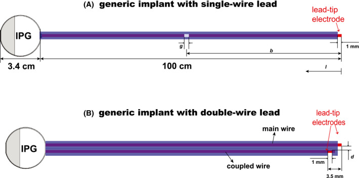
(A) Generic implant with a metallic IPG and a 100‐cm long single‐wire lead, with a break of dimension g at distance b from the lead‐tip. (B) Generic implant with a double‐wire lead (wire separation d) and 2 electrodes (lead‐tips). l indicates the distance of the wire break from the lead‐tip
For each lead model, the RF‐induced SAR distribution near the lead‐tip, the current distribution along the lead, and the transfer function were derived numerically using the finite‐difference time‐domain (FDTD) simulation platform Sim4Life V5.2 (ZMT Zurich MedTech AG (ZMT), Zurich, Switzerland) in a homogeneous tissue simulating medium (TSM) with the dielectric properties ε = 78 and σ = 0.47 S/m.
2.2. In vitro experimental validation
Four implants, all with the same IPG but different leads, were manufactured to validate the simulations: (1) m 1: a 100‐cm long intact single‐wire lead, (2) m 2: a 100‐cm long single‐wire lead with a wire break at 50 cm from the lead‐tip (1 mm plastic spacer inserted to ensure wire separation), (3) m 3: the same 100‐cm long broken single‐wire lead with a parallel intact 100‐cm long wire (wire distance d = 1.3 mm), and (4) m 4: a 50‐cm long single‐wire lead. This 50‐cm long lead was made by cutting the 100‐cm long lead at b = 50 cm from the lead‐tip and insulating the cut end, that is, a capped end. For the m 4 measurements, the IPG with the remaining 50‐cm lead was removed, making it a true representation of a 50‐cm long capped abandoned lead. The second lead‐tip for the double‐wire lead was 2.5 mm behind the first lead‐tip. The lead‐tip is formed by removing the insulation along 50% of the circumference to make a 1‐mm wide gap and expose the wire. The transfer function for each lead was measured with the piecewise excitation (piX) system (ZMT) and scaled using radiated SAR measurements performed with the medical implant test system (MITS, ZMT) and the dosimetric assessment system DASY6 (Schmid and Partner Engineering AG, Zurich, Switzerland) at 64 MHz in an ELIT1.5 phantom (ZMT) loaded with TSM with dielectric properties ε = 78 and σ = 0.47 S/m. The “touchless” technique28 was used to calculate the deposited in vitro lead‐tip power PISO−E by integrating the deposited power within a −30 dB volume around the lead‐tip with the aid of a numerically derived local power deposition distribution, which is co‐registered and scaled to the SAR measurements collected at 3 planes above the lead‐tip.
The confidence interval of the validation measurement of a given implant, exposure system, and polarization, was assessed for tests performed by the IT’IS Foundation following the methodology of JCGM 100:2008 (GUM), and is shown in the supporting information.
2.3. In vivo deposited power
The Tier 3 in vivo deposited power was estimated using the Medical Device Development Tool, IMAnalytics with MRI×ViP and BCLib.29 Four high‐resolution ViP anatomic models (http://itis.swiss/virtual‐population/virtual‐population/vip3/) were selected: Fats, Duke, Billie, and Thelonious.30 Each model was placed in 10 RF birdcage coils with different coil lengths and diameters, covering the envelope of commercial MR systems, as shown in Figure 2A. Each 2‐channel coil was tuned to resonate at 64 MHz at circular drive polarization. The patient models were placed supine in a head‐first scanning orientation, with the birdcage isocenter along the centerline of the patient model. Imaging positions from head‐to‐foot were considered for each model with a step size of 10 cm along the longitudinal axis, as shown in Figure 2C. For each coil, anatomic model, and landmark, the coil power was set such that the limiting SAR values of the normal operating mode, that is, either head averaged SAR (3.2 W/kg), whole‐body averaged SAR (2 W/kg), or partial‐body averaged SAR, was reached. For each ViP model, a generic spinal cord stimulator lead routing group, including 100 randomly generated lead routings, was evaluated. The routings ran underneath the skin from the left buttocks below the waistline, along the epidural space from the T10 vertebra, and terminated at the C1 vertebra. The magnitude of the tangential E‐field induced along the length of each routing is shown in the Supporting Information.
FIGURE 2.
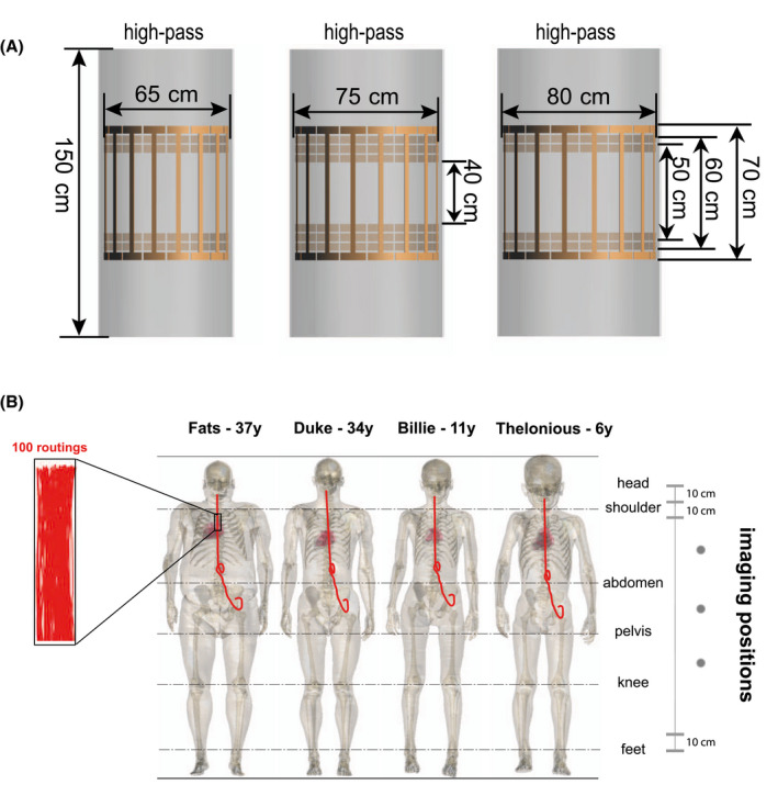
(A) Numeric models of the 10 2‐port RF coils in BCLib. (B) Illustration of the 4 selected ViP models with the spinal cord stimulator routing groups; each routing group contained 100 randomly generated lead routings. Imaging positions with a step size of 10 cm along the longitudinal axis from head‐to‐foot were selected
3. RESULTS
The current distribution of the single‐wire lead is shown in Figure 3A. The wire break causes a change in the effective electrical length of the lead. The non‐zero currents at some of the break points in Figure 3A are artifacts because of the limited spatial resolution of the current sensors. Figure 3B shows the current distribution and transfer function of the double‐wire leads. The current distribution of the double‐wire lead is substantially different compared to the single‐wire lead, which is because of the change in the characteristic impedance of the lead caused by the additional coupled wire. The deposited in vitro lead‐tip power under isoelectric conditions PISO−E , shown in Figure 4 as a function of the wire break position b, demonstrates that when the damaged wire segment attains the half‐wavelength of the field (ie, lead with a wire break at 50 cm), the RF‐induced and deposited in vitro lead‐tip power is ~30 times higher than for the intact single‐wire lead. The size of the wire gap has negligible influence (<0.01 dB) on the deposited in vitro lead‐tip power.
FIGURE 3.
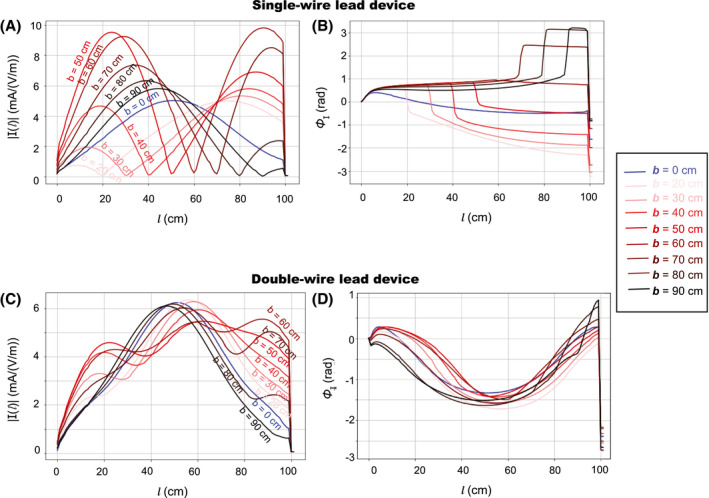
Amplitude (A) and phase (B) of the current distribution along the lead length l of the single‐wire lead and the double‐wire lead (C) and (D), numerically derived for 9 leads with different wire break positions b (distance from the lead‐tip), respectively
FIGURE 4.
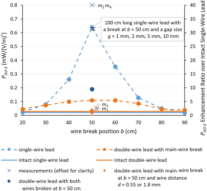
Deposited in vitro lead‐tip power PISO−E in for the (1) 100‐cm long single‐wire and the 100‐cm long double‐wire lead (wire distance d = 1.3 mm) with main‐wire break as a function of the wire break position b under isoelectric conditions. (2) 100‐cm long single‐wire lead with wire break at b = 50 cm and a gap size g = 1 mm, 2 mm, 5 mm, and 10 mm, (3) 100‐cm long double‐wire lead with wire distances d = 1.8 mm and 0.55 mm and the main‐wire broken at b = 50 cm, and (4) 100‐cm long double‐wire lead with wire distance d = 1.3 mm and both wires broken at b = 50 cm. Experimental validation measurements of the four 50‐cm break cases are shown with slight offset for clarity. m1: 100‐cm long intact single‐wire lead with IPG. m2: 100‐cm long single‐wire lead broken at b = 50 cm with IPG. m3: 100‐cm long double‐wire lead with main‐wire break at b = 50 cm and wire distance d = 1.3 mm and with IPG. m4: 50‐cm long single‐wire lead without IPG, that is, a 50‐cm capped abandoned lead
By adding an extra intact wire, or surprisingly even an extra broken wire, the RF‐induced deposited in vitro lead‐tip power enhancement decreased for the single‐wire lead from >30‐fold to <7‐fold. By changing the spacing between the broken and unbroken wire the enhancement factor varies by a factor of ~3. When the coupled wire was also broken at the 50‐cm position (ie, the 100‐cm long double‐wire lead with wire a distance d = 1.3 mm and both wires broken at b = 50 cm), the RF‐induced maximum deposited in vitro lead‐tip power PISO−E increased by ~2 compared to the case when only the main‐wire was broken at 50 cm, but was ~3 times lower than for the broken single wire.
All numeric results were experimentally validated, shown in Figure 4 as m1−m4, which agreed with the simulations within the estimated expanded uncertainty of 2.7 dB (see Supporting Information Tables S1‐S4). The RF‐induced deposited in vitro lead‐tip power of the lead broken at 50 cm was ~30 times higher than the intact lead; this enhancement decreased to <4 times when an intact wire was placed parallel to the wire with the break at 50 cm. Surprisingly, even a broken parallel lead reduced the enhancement to <7 times that of the intact case.
Finally, the Tier 3 deposited in vivo lead‐tip power (PTier 3) of the intact single‐wire lead and the single‐wire lead with a wire break at 50 cm was computed for more than 54,000 exposure scenarios. The corresponding tangential E‐fields are statistically summarized (see Supporting Information Figure S1). As previously shown,31 the variation of the RF‐induced SAR across different ViP models of the same generation can exceed 10 dB. Figure 5 shows that the mean and maximum enhancement ratio of the Tier 3 deposited in vivo lead‐tip power between the single‐wire lead with the wire broken at 50 cm (b = 50 cm) and the intact lead (b = 0 cm), computed for exposures where the lead‐tip power was ≥5% of the maximum value, varied from more than a 16‐fold enhancement to <0.2‐fold enhancement (reduction) depending on the exposure scenario.
FIGURE 5.
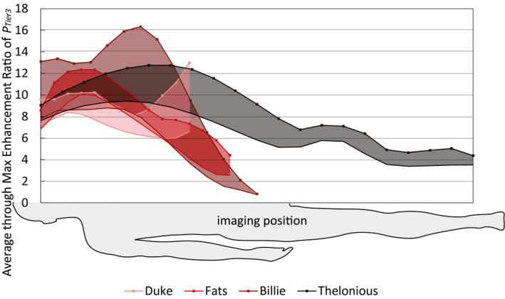
Mean (solid lines) and maximum (lines with markers) enhancement ratio of the Tier 3 deposited in vivo lead‐tip power (PTier 3), computed for exposures where the lead‐tip power was ≥5% of the maximum value, for the lead with a wire break at 50 cm over the intact single‐wire lead, across all RF‐coils and clinical routings, as a function of patient imaging position, normalized to the limits of the normal operating mode, that is, head averaged SAR of 3.2 W/kg, whole‐body averaged SAR of 2 W/kg, or partial‐body averaged SAR
4. DISCUSSION
This work demonstrates the potential for dangerously large RF‐induced heating during MR examinations by broken, abandoned, or cut leads when compared to intact leads. The maximum enhancement of the deposited lead‐tip power of a generic AIMD because of a wire break reached 30‐fold under isoelectric conditions (in vitro) and 16‐fold in realistic clinical exposures (in vivo), compared to the intact lead, with variations up to 2 orders of magnitude depending on the patient anatomy and scan position. Because of electromagnetic coupling, the presence of a nearby intact, or even broken, wire was seen to reduce the potential enhancement significantly, to ~4 times for the nearby intact wire and ~7 times for the nearby broken wire, respectively. Our experimental results confirm that a capped abandoned lead behaves the same as a broken lead with the same length from lead‐tip to the break point. The numerically extracted results were successfully validated by experiments within the combined uncertainty.
The charge buildup at the end of the wire is proportional to the spatial derivative of the current inside the wire. The associated field in the tissue is proportional to that charge build‐up, whereas the SAR and deposited power are proportional to the square of it. The parabolically shaped current profile along the wire shown in Figure 3 doubles in magnitude after breaking at 50 cm, while being squeezed into a 50‐cm length (further doubling the current derivative, resulting in a qualitatively estimated 4‐fold increase in charge build‐up and a 16‐fold 1 in power deposition). Quantitative evaluation of the computed current along the wire shows that the effective increase of the spatial derivative at the end is ~5.5‐fold—therefore, the deposited power is expected to increase in the order of 30‐fold, explaining the observed increase in Figure 4.
To evaluate if the findings are also relevant for clinical exposures, a simple test was performed using a set of generic leaded implants exposed to the fields along potential routings of a spinal cord stimulator for a large set of realistic examination conditions. Obviously, the observed enhancements are different for any other AIMD design, damage scenarios, clinical routings, and examination conditions.
All simulations and measurements were performed at 64 MHz, corresponding to 1.5T MR systems; qualitatively similar results are expected at the higher frequencies used by 3T and 7T MR systems, with the main difference being the break length(s) and geometries, at which large enhancement of deposited power is attained.
These potential heating enhancements should be considered, together with the probability of damage and/or the use of a pre‐scan diagnostic, such as an impedance check, when performing risk assessment for MR examinations or device labeling. Our results indicate that multi‐wire leads must be thoroughly tested for the worst‐case break configuration before claims about their safety in the MR environment with broken wires can be made. Without comprehensive evaluation of broken wires, the large enhancement of RF‐induced deposited lead‐tip power, both in vitro and in vivo, found in this study, and the potential consequences of serious tissue damage, warrant to contraindicate AIMD patients with broken, abandoned, or cut leads from MR examinations. It also calls for further investigations into how abandoned leads (those that cannot be removed because of medical reasons) can be put into a configuration, which does not produce more RF‐induced lead‐tip power than when the lead is connected to the IPG. Such a lead configuration would allow patients with MR conditional AIMDs access to MR examination even when their MR conditional lead is no longer connected to the IPG.
DISCLAIMER
The mention of commercial products, their sources or their use in connection with material reported herein is not to be construed as either an actual or implied endorsement of such products by the Department of Health and Human Services.
Supporting information
FIGURE S1 Tier 3 95% Etan along clinical routing groups defined in Figure 2C for circular drive polarization and normal operating mode
TABLE S1 Uncertainty of the normalized transfer function model of the test item
TABLE S2 Combined uncertainty of incident field exposure, because of the RF coil and anatomic model
TABLE S3 Uncertainty of local SAR enhancement measured via radiated testing in the MITS using DASY6 with an EX3D SAR probe
TABLE S4 Estimated validation uncertainty
ACKNOWLEDGMENTS
This work was supported by the EMPIR grant 17IND01 MIMAS, which is co‐funded by the European Union's Horizon 2020 research and innovation program and the EMPIR participating states. The authors thank Drs. Arya Fallahi and Esra Neufeld from IT'IS Foundation as well as Dr. Sabine Regel from SR Scientific GmbH for their insightful comments and careful reading of the manuscript, and Dr. Maurice Cox from NPL for his review of the confidence interval estimation.
Yao A, Goren T, Samaras T, Kuster N, Kainz W. Radiofrequency‐induced heating of broken and abandoned implant leads during magnetic resonance examinations. Magn Reson Med. 2021;86:2156–2164. 10.1002/mrm.28836
Funding information
EMPIR, Grant/Award Number: 17IND01 MIMAS; co‐funded by the European Union’s Horizon 2020 research and innovation program and the EMPIR participating states
REFERENCES
- 1.Nyenhuis JA, Park S‐M, Kamondetdacha R, Amjad A, Shellock FG, Rezai AR. MRI and implanted medical devices: basic interactions with an emphasis on heating. IEEE Trans Device Mater Reliab. 2005;5:467‐480. [Google Scholar]
- 2.Yeung CJ, Susil RC, Atalar E. RF safety of wires in interventional MRI: using a safety index. Magn Reson Med. 2002;47:187‐193. [DOI] [PubMed] [Google Scholar]
- 3.Cabot E, Llyod T, Christ A, et al. Evaluation of the RF heating of a generic deep brain stimulator exposed in 1.5 T magnetic resonance scanners. Bioelectromagnetics. 2013;34:104‐113. [DOI] [PubMed] [Google Scholar]
- 4.Henderson JM, Tkach J, Phillips M, Baker K, Shellock FG, Rezai AR. Permanent neurological deficit related to magnetic resonance imaging in a patient with implanted deep brain stimulation electrodes for Parkinson's disease: case report. Neurosurgery. 2005;57:E1063. [DOI] [PubMed] [Google Scholar]
- 5.Henrikson CA, Brinker JA. How to prevent, recognize, and manage complications of lead extraction. Part I: avoiding lead extraction—infectious issues. Heart Rhythm. 2008;5:1083‐1087. [DOI] [PubMed] [Google Scholar]
- 6.Henrikson CA, Brinker JA. How to prevent, recognize, and manage complications of lead extraction. Part II: avoiding lead extraction—noninfectious issues. Heart Rhythm. 2008;5:1221‐1223. [DOI] [PubMed] [Google Scholar]
- 7.Henrikson CA, Brinker JA. How to prevent, recognize, and manage complications of lead extraction. Part III: procedural factors. Heart Rhythm. 2008;5:1352‐1354. [DOI] [PubMed] [Google Scholar]
- 8.Sloman G, Strathmore N. Permanent pacemaker lead extraction. Pacing Clin Electrophysiol. 1993;16:2331‐2332. [DOI] [PubMed] [Google Scholar]
- 9.Krishnan SC, Epstein LM. Initial experience with a laser sheath to extract chronic transvenous implantable cardioverter‐defibrillator leads. Am J Cardiol. 1998;82:1293‐1295. [DOI] [PubMed] [Google Scholar]
- 10.Kalahasty G, Ellenbogen KA. Management of the patient with implantable cardioverter‐defibrillator lead failure. Circulation. 2011;123:1352‐1354. [DOI] [PubMed] [Google Scholar]
- 11.Bansal S. NCT04478773: Evaluating MRI Scanning in Patients with Fractured or Abandoned Endocardial Leads. Lancaster, PA: US Clinical Trial. 2020‐2022. https://clinicaltrials.gov/ct2/show/NCT04478773. Accessed June 1, 2021. [Google Scholar]
- 12.Acikel V, Magrath P, Parker SE, et al. RF induced heating of pacemaker/ICD lead‐tips during MRI Scans at 1.5T and 3T: evaluation in cadavers. J Cardiovasc Magn Reson. 2016;18:(S1). [Google Scholar]
- 13.Higgins JV, Gard JJ, Sheldon SH, et al. Safety and outcomes of magnetic resonance imaging in patients with abandoned pacemaker and defibrillator leads. Pacing Clin Electrophysiol. 2014;37:1284‐1290. [DOI] [PubMed] [Google Scholar]
- 14.Kim J, Hwang J, Choi JH, et al. Frequency and clinical impact of retained implantable cardioverter defibrillator lead materials in heart transplant recipients. PLOS ONE. 2017;12:e0176925. [DOI] [PMC free article] [PubMed] [Google Scholar]
- 15.Morris MF, Verma DR, Sheikh H, Su W, Pershad A. Outcomes after magnetic resonance imaging in patients with pacemakers and defibrillators and abandoned leads. Cardiovasc Revasc Med. 2018;19:685‐688. [DOI] [PubMed] [Google Scholar]
- 16.Padmanabhan D, Kella DK, Mehta R, et al. Safety of magnetic resonance imaging in patients with legacy pacemakers and defibrillators and abandoned leads. Heart Rhythm. 2018;15:228‐233. [DOI] [PubMed] [Google Scholar]
- 17.Russo RJ, Costa HS, Silva PD, et al. Assessing the risks associated with MRI in patients with a pacemaker or defibrillator. N Engl J Med. 2017;376:755‐764. [DOI] [PubMed] [Google Scholar]
- 18.Jensen TS, Chin J, Ashby L, et al., Decision Memo for Magnetic Resonance Imaging (MRI) (CAG‐00399R4). Woodlawn, MD: US Centers for Medicare and Medicaid Services; 2018. https://www.cms.gov/medicare‐coverage‐database/details/nca‐decision‐memo.aspx?NCAId=289. Accessed June 1, 2021. [Google Scholar]
- 19.Verma A, Ha ACT, Dennie C, et al. Canadian Heart Rhythm Society and Canadian Association of Radiologists consensus statement on magnetic resonance imaging with cardiac implantable electronic devices. Can J Cardiol. 2014;30:1131‐1141. [DOI] [PubMed] [Google Scholar]
- 20.Gakenheimer‐Smith L, Etheridge SP, Niu MC, et al. MRI in pediatric and congenital heart disease patients with CIEDs and epicardial or abandoned leads. Pacing Clin Electrophysiol. 2020;43:797‐804. [DOI] [PMC free article] [PubMed] [Google Scholar]
- 21.Liorni I, Neufeld E, Kühn S, et al. Novel mechanistic model and computational approximation for electromagnetic safety evaluations of electrically short implants. Phys Med Biol. 2018;63:225015. [DOI] [PubMed] [Google Scholar]
- 22.Park SM, Kamondetdacha R, Nyenhuis JA. Calculation of MRI‐induced heating of an implanted medical lead wire with an electric field transfer function. J Magn Reson Imaging. 2007;26:1278‐1285. [DOI] [PubMed] [Google Scholar]
- 23.Langman DA, Finn JP, Ennis DB. Abandoned pacemaker leads are a potential risk for patients undergoing MRI. Pacing Clin Electrophysiol. 2011;34:1051‐1053. [DOI] [PubMed] [Google Scholar]
- 24.Mattei E, Gentili G, Censi F, Triventi M, Calcagnini G. Impact of capped and uncapped abandoned leads on the heating of an MR‐conditional pacemaker implant. Magn Reson Med. 2015;73:390‐400. [DOI] [PubMed] [Google Scholar]
- 25.Balmer C, Gass M, Dave H, Duru F, Luechinger R. Magnetic resonance imaging of patients with epicardial leads: in vitro evaluation of temperature changes at the lead tip. J Interv Card Electrophysiol. 2019;56:321‐326. [DOI] [PubMed] [Google Scholar]
- 26.Murbach M, Nasseri N, Neufeld N, Kuster N. Safety Concerns for MRI Heating of Fractured and Adjacent Metallic Implants. Montpellier, France: BioEM; 2019. [Google Scholar]
- 27.Guo R, Zheng J, Wang Y, et al. Computational and experimental investigation of RF‐induced heating for multiple orthopedic implants. Magn Reson Med. 2019;82:1848‐1858. [DOI] [PubMed] [Google Scholar]
- 28.Aiping Y, Earl Z, Niels K. Data‐driven experimental evaluation method for the safety assessment of implants with respect to RF‐induced heating during MRI. Radio Sci. 2018;53:700‐709. [Google Scholar]
- 29.US Food and Drug Administration (FDA) . MDDT Summary Of Evidence and Basis of Qualification Decision for IMAnalytics with MRIxViP1.5T/3.0T and BCLIB. Silver Spring, MD: US Food and Drug Administration (FDA); 2021. https://www.fda.gov/media/148922/download. Accessed June 1, 2021. [Google Scholar]
- 30.Gosselin MC, Neufeld E, Moser H, et al. Development of a new generation of high‐resolution anatomical models for medical device evaluation: the virtual population 3.0. Phys Med Biol. 2014;59:5287‐5303. [DOI] [PubMed] [Google Scholar]
- 31.Aiping Y, Earl Z, Eugenia C, et al. Anatomical model uncertainty for RF safety evaluation of metallic implants under MRI exposure. Bioelectromagnetics. 2019;40:458‐471. [DOI] [PubMed] [Google Scholar]
- 32.Tolga G, Aiping Y, Niels K. Confidence Interval of ISO 10974 Tier 3 Evaluations. Zurich: IT'IS Foundation; 2020. [Google Scholar]
Associated Data
This section collects any data citations, data availability statements, or supplementary materials included in this article.
Supplementary Materials
FIGURE S1 Tier 3 95% Etan along clinical routing groups defined in Figure 2C for circular drive polarization and normal operating mode
TABLE S1 Uncertainty of the normalized transfer function model of the test item
TABLE S2 Combined uncertainty of incident field exposure, because of the RF coil and anatomic model
TABLE S3 Uncertainty of local SAR enhancement measured via radiated testing in the MITS using DASY6 with an EX3D SAR probe
TABLE S4 Estimated validation uncertainty