Abstract
A micromagnetic study is carried out on the role of using topology to stabilize different magnetic textures, such as a vortex or an anti-vortex state, in a magnetic heterostructure consisting of a Permalloy disk coupled to a set of nanomagnetic bars. The topological boundary condition is set by the stray field contributions of the nanomagnet bars and thus by their magnetization configuration, and can be described by a discretized winding number that will be matched by the winding number of the topological state set in the disk. The lowest number of nanomagnets that defines a suitable boundary is four, and we identify a critical internanomagnet angle of 225° between two nanomagnets, at which the boundary fails because the winding number of the nanomagnet configuration no longer controls that of the disk magnetization. The boundary also fails when the disk-nanomagnets separation is > 50 nm and for disk diameters > 480 nm. Finally, we provide preliminary experimental evidence from magnetic force microscopy studies in which we demonstrate that an energetically unstable, anti-vortex-like structure can indeed be stabilized in a Permalloy disk, provided that the appropriate topological conditions are set
Keywords: Micromagnetics, neuromorphic computing, topology, magnetic force microscopy
I. INTRODUCTION
Magnetic textures in lithographically-patterned structures, for example a vortex state [1,2] in a Permalloy (Py) disk, can be leveraged in neuromorphic computing applications such as for speech recognition [3,4]. However, realizing such applications using Permalloy disks is typically achieved by synchronization of vortex core oscillations in the disks, which act as an array of “coupled” oscillators. This is typically a highly dynamic process, with the cores oscillating in the gigahertz regime. The inter-oscillator coupling is established by a variety of schemes, for example via the magnetic stray field interaction between the two oscillators [5,6]. Alternatively, we can envision a quasi-dynamic process in which different magnetic textures would control the coupling response in arrays of permalloy disks. Such an array would be similar to the resistive random access memory (RRAM) approach in which particular paths across the memory correspond to specific resistance values [7].
Here, we take the quasi-dynamic path by creating a tunable mechanism to stabilize different magnetic textures in Py nanodisks, established via a new approach to internanomagnet coupling. As a preliminary step, we demonstrate that the type of magnetic texture stabilized in a Py disk can tuned by controlling its magnetic boundary using a set of adjacent nanomagnet bars [8]. Previous efforts to stabilize magnetic textures, especially the more unusual antivortex structure, were carried out by altering the shape of the magnetic element [9,10] or by using an applied field to force an anti-vortex configuration in a square nanomagnet [11]. In addition, an approach to controlling the vortex chirality in a Permalloy disk using two adjacent rhomboid-shaped nanomagnets has been demonstrated [12].
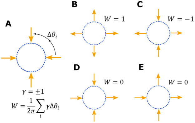
The topological boundary condition is described in the schematic in Figure 1, in which a magnetic region (blue dotted circle) is surrounded by four Ising spins with fixed moment orientation (yellow arrows). The boundary is defined by the number of surrounding Ising spins and their collective magnetization configuration. In order to simplify our terminology, we introduce a discretized version of the winding number (W) such that, , where Δθi is the difference in angles between two neighboring nanomagnets at locations i and i + 1 and γ is the change in orientation of the Ising spins, (see Fig. 1A) [13]. The boundary can therefore be defined by the winding number associated with the Ising spin configuration because the physical parameter that influences the disk configuration is the stray field from the surrounding nanomagnets.
Fig. 1.
A discrete form of the topological winding number is introduced. Schematics show the winding numbers associated with different Ising spin configurations (yellow arrows).
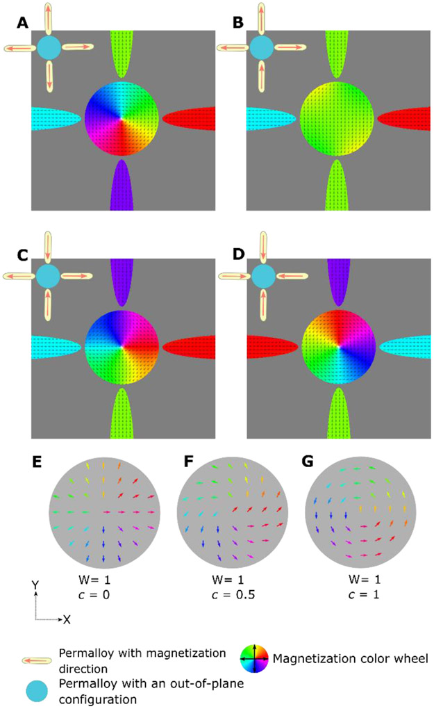
Micromagnetic simulations are carried out using the MuMax software (ver. 3.9.1) [14] on a model system that comprises a Py disk surrounded by four ellipseal permalloy (Py), Ni80Fe20, nanomagnets. The results of some of the simulations are shown in Figure 2. The moment configurations in the Py ellipses are fixed to give a specific winding number as discussed above. In all simulations the Py disk is initialized with its magnetization out-of-plane and then allowed to relax at room temperature, after the simulation was run for 1 ns. We use a saturation magnetization (Ms) of 800 kAm−1, an exchange stiffness (Aex) of 1.3 × 10⁻¹¹ Jm−1, a damping constant (α) of 0.02, and a uniaxial anisotropy constant (Ku1) of 5e+2 Jm−3 for Py. The diameter of the Py disk is 300 nm, and the Py ellipses are 600 nm long and 100 nm wide. The thickness of the ellipses and of the disk is 10 nm. The ellipses are positioned 30 nm from the Py disk and thus a purely dipolar interaction can be assumed.
Fig. 2.
(A–D) Micromagnetic simulations of the relaxed magnetization state in a Py disk for winding numbers of the boundary of +1 (A and D), 0 (B), and −1 (C). (E–G) Topologically-equivalent magnetic textures (all with a winding number +1) belonging to different topological sectors, i.e. different values of c.
Our simulations, examples of which are shown in Figure 2, show that the winding number of the magnetic structure induced in the Py disk does indeed match the winding number of the magnetic configuration in the surrounding Py ellipses. For example, a vortex state is observed in the disk only if the Py nanomagnets carry a winding number of +1, as shown in Fig. 2A and Fig. 2D, and we further see that the nanomagnet spin direction does not influence the vortex chirality. Similarly, an anti-vortex state, i.e. a soliton with a winding number of −1, is realized when the winding number of the magnetic configuration in the surrounding nanomagnets is also −1 (Fig. 2D). Further, when the winding number is 0, no soliton was observed (see Fig. 2B). Thus, a mathematical description of the topology can be made by considering a configuration with winding number W, the angle between the direction of the in-plane magnetization (M) and the X-axis, i.e. the azimuthal angle (Φ), can be written as
| (1) |
Here, X and Y correspond to the position of the magnetization vector in the X-Y plane, while (xo,yo) is the location of the vortex core. c is the chirality, which is the change in angle of a particular magnetization vector with respect to a reference magnetization vector in the disk [15,16]. Typically, the values of c are integers such as 0, 1, 2, but c can also take fractional values such as 0.5. Therefore, we can identify the first term in equation (1) as describing the overall topology of the observed soliton in the disk (for example a vortex state), while the second term describes the magnetization configuration within a particular topological sector defined by a change in c. Thus, from a topological sense, even though the magnetization configuration in the Py ellipses that define the topological boundary condition look different from that observed in the disk, they can still be topologically equivalent. An example of topologically-identical magnetic structures that do not show the same configuration, is shown schematically in Figures 2 (E-G).
Now, we will address the observed biasing of chirality in Figures 2A and 2D. Despite the degeneracy of the two chiral states c = ±1 for W = 1 we observe that the chirality of the vortices is determined by the initial conditions in our simulations. When the boundary condition has the magnetization within the ellipses directed away from the disk, the disk obtains a counter-clockwise vortex, chirality of c = 1, this is shown in Fig. 2A. Likewise, when the magnetization within the ellipses is directed towards the disk, the vortex is oriented clockwise, as shown in Fig. 2D. This deterministic chirality can be understood as originating from a chiral oscillation introduced into the disk while relaxing from the out-of-plane initial configuration, after the initial applied field is removed. The chiral rotation of the magnetization is described by the Landau-Lifshitz-Gilbert equation. For example, the stray field, Heff, from the ellipses oriented away from the disk can be treated as oriented along the radial direction, with an initial out-of-plane magnetic configuration, the magnetization, M in the disc will obtain a rotation in the azimuthal direction:
It is apparent the motion in the azimuthal direction will depend on the initial configuration of the disc, whether ± , and the boundary conditions set by the ellipses. We find the chirality to be set opposite of the direction of rotation. This opens the door to controlling the chirality of topological magnetic structures by our method.
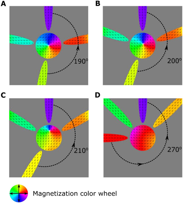
To further explore how changing nanomagnet configuration influences the disk, we carry out micromagnetic simulations in which the position of three of the nanomagnets are varied while the fourth is fixed, as shown in Figure 3. The bottom nanomagnet’s position varies by angles (Δϑ) of 10°, 20°, 30° and 90° from its normal position, as shown in Figure 3 (A-D), which corresponds to the largest angle between the top and the bottom nanomagnets (ϑmax) being 190°, 200°, 210°, and 270° respectively. For each value of Δϑ for the bottom nanomagnet, the two nanomagnets lying horizontal to the plane are placed closer to the top nanomagnet by (Δϑ/2) such that their angles with respect to the top nanomagnet are 80°, 70°, 60°, and 45°
Fig. 3.
(A–D) Micromagnetic simulation of a Py disk with surrounding elliptical nanomagnets, as a function of nanomagnet position. The associated winding number of the nanomagnets is shown in top left. (A-C) An anti-vortex forms in the disk for values of (ϑmax) of 190°, 200°, and 210°. (D) Uniform magnetization observed for (ϑmax)=225°.
From a topological perspective, even though the winding number is −1, we found that there is a critical value of ϑmax of 225°, above which the nanomagnets no longer influence the disk and the anti-vortex core is no longer stable (see Fig. 3D). The boundary condition is set by a byproduct of a complex interaction of stray field between the surrounding nanomagnets and the Py disk, and the inherent exchange energy within the Py disk. In particular, the energy of the anti-vortex is highly correlated to the domain wall energy per unit area (surface tension) and to the length of the Néel walls that it contains [17,18]. Therefore, for cases in which the spread of stray field is asymmetric, there is a significant increase in the surface tension of the Néel walls and thus the anti-vortex collapses.
If the magnetization in the nanomagnets no longer influences the behavior of the disk magnetization, we consider the boundary condition to have broken down, and this will occur if the parameters describing the individual nanomagnets do not meet a particular criterion or set of criteria [19,20]. To explore further, on the role of parameters in describing how the magnetic texture in the permalloy disk changes, we perform micromagnetic simulations on nanomagnets with thicknesses of 5 nm, 10 nm, and 20 nm. For each thickness, the effect of changing the distance between the nanomagnets and the Py disk is also explored (separations of 5 nm, 50 nm, and 100 nm). We also analyze the effect of changing the diameter of the Py disk and carry out simulations for diameters of 180 nm, 280 nm, 480 nm, and 780 nm. As for our other simulations, the magnetization in the Py disk is initialized in an out-of-plane direction, while the magnetization directions in the surrounding Py nanomagnets is fixed along the nanomagnet length. We chose a boundary with a winding number of −1 (see Fig. 2D) such that we expect an anti-vortex to stabilize in the Py disk. We find that an anti-vortex is only stabilized over a very narrow range of nanomagnet parameters. Even though simulations starting with an antivortex configuration suggest that it is metastable, we never observe one in simulations starting with an out-of-plane configurations for a disk diameter ≥ 480 nm. Additionally, for a disk-nanomagnet separation ≥50 nm the anti-vortex state occurred in fewer simulations as we varied other details. This reduced frequency leads us to conclude that the stray field interaction giving rise to the boundary condition has a weaker influence on the disk magnetization as separation increases.
Even though we use the term “stabilize” to describe the magnetic textures that we observe, corresponding to different topological winding numbers set by the nanomagnets, this does not imply that the magnetic textures are lower in energy compared to those found in isolated Py disks. In fact, our simulations show that a vortex core can be expelled from a Py disk surrounded by nanomagnets with configuration having winding number of +1, with the application of an in-plane field of <16 kA/m (200 Oe). Whether or not the vortex core is expelled from a Py disk is proportional to the ratio of the effective applied field (H) and the saturation magnetization (Ms), i.e. : the effective field is the vector sum of the stray field from the surrounding nanomagnets and the applied field, so for certain nanomagnet configurations expulsion of the core occurs at a lower applied field than for an isolated Py disk. A solution to the problem of core expulsion at low applied fields is to choose a magnetic material for the disk that has a large value of Ms – clearly other factors that influence the energetics of the solitons, such as anisotropy and temperature should also be considered when choosing a material.
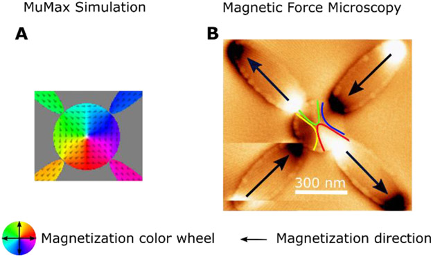
We have lithographically patterned arrays of 300 nm diameter Py disks each surrounded by four Py ellipses at a separation of 30 nm from the disk. The Py ellipses are 500 nm in length and 200 nm wide, with a thickness of 10 nm. We initialize the disks by applying a magnetic field of ≈1 T in the out-of-plane direction and then remove it, letting the disks and the surrounding nanomagnets undergo a room temperature field-free relaxation. The relaxed structures are imaged using magnetic force microscopy (MFM) using a low moment tip to minimize tip-induced stray field interactions with the magnetization in the disks and nanomagnets. We image a total of 35 disks and in two instances the surrounding nanomagnets relax to give a boundary with winding number = −1. In both cases, the magnetic texture in the disk closely resembled an anti-vortex wall, as shown in Fig. 4B, although we do not have sensitivity to out-of-plane magnetization to detect a core at the center.
Fig. 4.
(A) Micromagnetic simulation of an anti-vortex state with a winding number of −1, in which the boundary state also has a winding number of −1. (B) MFM image of an anti-vortex-like magnetic texture in a Py disk, for which the surrounding Py nanomagnets create a boundary with winding number of −1.
For the remaining disks, the surrounding nanomagnets relax to a configuration with winding number = 0, and the magnetization in the disks was uniform. We believe that this occurs because the surrounding Py nanomagnets are also subjected to the out-of-plane field and upon its removal the entire system relaxes to a minimum energy such that the boundary has a winding number = 0 and the disk has uniform magnetization (winding number = 0). This is confirmed in our micromagnetic simulations, which show that the energy of a Py disk magnetic configuration with a winding number = 0 is almost an order in magnitude lower than for any other winding number.
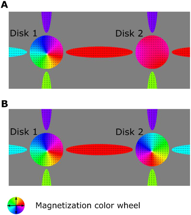
As a first step in considering networks of disks, we model a two-disk, with a shared nanomagnet between the two disks. The micromagnetic simulations are carried out in the same way as those described above: the Py disks were initialized with out-of-plane magnetization while the surrounding nanomagnets had their magnetization configuration frozen to set a specific winding number. Initially, the boundary for disk 1 is set with W = −1, while for disk 2 the boundary is set with W = 0. We find that the disks indeed relax to a magnetic texture with the same winding number as the surrounding boundary: an antivortex in disk 1, and a no topological soliton is observed in disk 2 (as shown in Figure 5A). Further, when the winding number of the boundary for disk 2 is changed to +1, we observe a vortex in disk 2 (Fig. 5B). Thus, we show that even for coupled disks, the boundary holds. From a practical standpoint, one could construct an exchange-mediated boundary i.e. the boundary will be in physical contact with the permalloy disk– thus electrical currents could be implemented to measure resistance across different paths.
Fig. 5.
MuMax simulations of coupled disks, in which two Permalloy disks are interacting with each other across a connecting nanomagnet. (A) the magnetization in the disks corresponds to an anti-vortex (disk 1) and a soliton free state (disk 2) corresponding to their respective boundary s with W= −1 and W= 0 respectively. (B) Boundary for disk 2 changed to have W= +1 – a vortex is now stabilized.
We have developed a novel mechanism to control the formation of different topological magnetic structures by altering their boundary through topological considerations. We believe that our results possibly also provide a robust interpretation to similar behavior observed elsewhere [9,11,21]. In addition, a winding number set by four nanomagnets can provide us with 3 unique magnetic textures in the Permalloy disk, which could be used in memory applications. From a neuromorphic standpoint, we envision an array of Permalloy disks connected via a tunable boundary. We also found that the chirality of the vortex can be tuned by changing topological sector of the boundary. In such an array, the magnetic textures observed in a disk or group of disks would be strongly dependent on how the winding number is altered– thus leading to applications in schemes such as Spiking Time Dependent Plasticity (STDP), similar to those observed in resistive neuromorphic computing solutions [22].
Acknowledgments
This work was supported as part of the Quantum Materials for Energy Efficient Neuromorphic Computing (Q-MEEN-C), an Energy Frontier Research Center funded by the U.S. Department of Energy, Office of Science, Office of Basic Energy Sciences under Award # DE-SC0019273. F.B. acknowledges support by the U.S. Department of Energy, Office of Science, Office of Basic Energy Sciences, Materials Science and Engineering Division.
References
- [1].Cowburn RP, Koltsov DK, Adeyeye AO, Welland ME, and Tricker DM, Physical Review Letters 83, 1042 (1999). [Google Scholar]
- [2].Shinjo T, Okuno T, Hassdorf R, Shigeto K, and Ono T, Science 289, 930 (2000). [DOI] [PubMed] [Google Scholar]
- [3].Grollier J, Querlioz D, and Stiles MD, Proceedings of the IEEE 104, 2024 (2016). [DOI] [PMC free article] [PubMed] [Google Scholar]
- [4].Torrejon J, Riou M, Araujo F, Tsunegi S, Khalsa G, Querlioz D, Bortolotti P, Cros V, Yakushiji K, Fukushima A et al. , Nature 547, 428 (2017). [DOI] [PMC free article] [PubMed] [Google Scholar]
- [5].Locatelli N, Hamadeh A, Araujo F, Belanovsky A, Skirdkov P, Lebrun R, Naletov V, Zvezdin K, Munoz M, Grollier J et al. , Scientific Reports 5, 17039 (2015). [DOI] [PMC free article] [PubMed] [Google Scholar]
- [6].Vogel A, Drews A, Weigand M, and Meier G, AIP Advances 2, 042180 (2012). [Google Scholar]
- [7].Chiolerio A, Chiappalone M, Ariano P, and Bocchini S, Frontiers in Neuroscience 11 (2017). [DOI] [PMC free article] [PubMed] [Google Scholar]
- [8].Mermin ND, Reviews of Modern Physics 51, 591 (1979). [Google Scholar]
- [9].Martens M, Kamionka T, Drews A, Krüger B, and Meier G, Journal of Applied Physics 112, 013917 (2012). [Google Scholar]
- [10].Gliga S, Yan M, Hertel R, and Schneider CM, Physical Review B 77, 060404 (2008). [Google Scholar]
- [11].Goto M, Nozaki Y, and Sekiguchi K, Japanese Journal of Applied Physics 54, 023001 (2015). [Google Scholar]
- [12].Haldar A and Adeyeye AO, Applied Physics Letters 106, 032404 (2015). [Google Scholar]
- [13].Hertel R and Schneider CM, Physical Review Letters 97, 177202 (2006). [DOI] [PubMed] [Google Scholar]
- [14].Vansteenkiste A, Leliaert J, Dvornik M, Helsen M, Garcia-Sanchez F, and Waeyenberge BV, AIP Advances 4, 107133 (2014). [Google Scholar]
- [15].Nagaosa N and Tokura Y, Nature Nanotechnology 8, 899 (2013). [DOI] [PubMed] [Google Scholar]
- [16].Kim J-V, Physical Review B 92, 014418 (2015). [Google Scholar]
- [17].Chern G-W, Youk H, and Tchernyshyov O, Journal of Applied Physics 99, 08Q505 (2006). [Google Scholar]
- [18].Youk H, Chern G-W, Merit K, Oppenheimer B, and Tchernyshyov O, Journal of Applied Physics 99, 08B101 (2006). [Google Scholar]
- [19].Guslienko KY, Novosad V, Otani Y, Shima H, and Fukamichi K, Applied Physics Letters 78, 3848 (2001). [Google Scholar]
- [20].Novosad V, Guslienko KY, Shima H, Otani Y, Fukamichi K, Kikuchi N, Kitakami O, and Shimada Y, IEEE Transactions on Magnetics 37, 2088 (2001). [Google Scholar]
- [21].Gliga S, Hertel R, and Schneider CM, Journal of Applied Physics 103, 07B115 (2008). [Google Scholar]
- [22].Sengupta A and Roy K, Applied Physics Reviews 4, 041105 (2017). [Google Scholar]


