Abstract
This paper reports the development of a fully actuated body-mounted robotic assistant for MRI-guided low back pain injection. The robot is designed with a 4-DOF needle alignment module and a 2-DOF remotely actuated needle driver module. The 6-DOF fully actuated robot can operate inside the scanner bore during imaging; hence, minimizing the need of moving the patient in or out of the scanner during the procedure, and thus potentially reducing the procedure time and streamlining the workflow. The robot is built with a lightweight and compact structure that can be attached directly to the patient’s lower back using straps; therefore, attenuating the effect of patient motion by moving with the patient. The novel remote actuation design of the needle driver module with beaded chain transmission can reduce the weight and profile on the patient, as well as minimize the imaging degradation caused by the actuation electronics. The free space positioning accuracy of the system was evaluated with an optical tracking system, demonstrating the mean absolute errors (MAE) of the tip position to be 0.99±0.46 mm and orientation to be 0.99±0.65°. Qualitative imaging quality evaluation was performed on a human volunteer, revealing minimal visible image degradation that should not affect the procedure. The mounting stability of the system was assessed on a human volunteer, indicating the 3D position variation of target movement with respect to the robot frame to be less than 0.7 mm.
I. INTRODUCTION
Low back pain is a common symptom in both adults and children, and it is the most common source of job-related disability and a main contributor to missed work days [1]. Lumbar spinal injection is a common treatment for chronic pain, which involves delivery of pain relief medications locally to the site of pain source. Low back pain injections are usually performed in the lower back and pelvis area and require targeting of sub-millimeter nerves, small muscular compartments, and thin anatomic spaces [2], [3]. Conventional lumbar spinal injection procedures utilize fluoroscopy or CT to provide needle guidance, which can cause ionizing radiation exposure to both patients and clinicians. Ultrasound is free of ionizing radiation, however, nerve visualization is user dependent and can be significantly difficult. Magnetic resonance imaging (MRI) is an excellent imaging modality, owing to its capability to offer unmatched anatomical details and high soft tissue contrast without exposing the clinicians or patients to ionizing radiation, which is especially critical in pediatric patients [4]. Although the benefits of MRI are encouraging, the strong magnetic and radio frequency field, and the tightly confined scanner bore (60-70 cm) result in significant challenges to develop robotic systems that can operate within the MRI environment.
In terms of mounting mechanism, MRI-guided robotic systems can be classified in two categories: table-mounted and body-mounted. Table-mounted robots are usually mounted to the scanner table. Patient is required to remain still during the procedure to achieve steady relative position with respect to the robot. However, patient motion is unavoidable, especially for procedures that require longer time. Table-mounted robots have been investigated widely for MRI-guided interventional procedures including stereotactic neurosurgery [5]–[8], prostate cancer therapy [9]–[13], and breast tissue biopsy [14], [15]. Conversely, body-mounted robots are attached directly to the patient via straps, which can minimize effects of patient motion by moving with the patient. Therefore, they can be designed with compact and lightweight profile, because they do not need additional support frames. Wu et al. designed a coil-mounted robotic positioner for MRI-guided cryoablation [16]. A coil-mounted robotic device with double ring mechanism was designed by Hata et al. for MRI-guided renal interventions [17]. Hunger et al. developed a body-mounted cable-driven robot to perform CT and MRI-guided interventions [18]. Walsh et al. designed a 4-DOF patient-mounted teleoperated needle guidance device for CT-guided interventions [19]. Although these robots have shown promise, most of them are proof-of-concept prototypes and only a few have made it to clinical trials.
In our previous study, we developed a 2-DOF remotely actuated needle driving device with novel beaded chain transmission [20] and a 4-DOF needle alignment manipulator [21]. In this study, we adopted the design of the 2-DOF needle driver with improved performance and integrated it with the 4-DOF needle alignment module, enabling a 6-DOF fully actuated robotic system for MRI-guided low back pain injection. The robot is designed with a compact and lightweight profile, which can be directly attached to the patient’s back through straps, minimizing the effects of patient motion. The primary contributions of this study include: 1) development of a 6-DOF fully actuated body-mounted robot for MRI-guided lumbar spinal injection, 2) kinematic and finite element analysis of the robot mechanism to secure a procedure with sufficient workspace and stiffness, and 3) experimental evaluation of the system targeting accuracy via free space assessment, as well as qualitative imaging quality validation and mounting stability evaluation on a human volunteer.
II. MECHANICAL SYSTEM DESIGN
A. Design Requirements
This robotic assistant is designed to be attached directly to the lower back of a patient and to place a needle under intraoperative MRI-guidance. 6-DOF motion is required to place a needle to a target anatomy: four DOFs to align the needle and two DOFs to insert and rotate the needle. In clinical practice, for the sake of safety, the needle insertion and rotation are desired to be controlled by the radiologist directly. Therefore, this robotic assistant is designed with two major modules: a 4-DOF needle alignment module and a 2-DOF needle driver module, as illustrated in Fig. 2. During the procedure, the 4-DOF needle alignment module is firstly actuated to align the needle and then locked in place for the remainder of the procedure. Once the needle is aligned, the radiologist can insert the needle with the 2-DOF needle driver module under intraoperative continuous MRI-guidance.
Fig. 2.
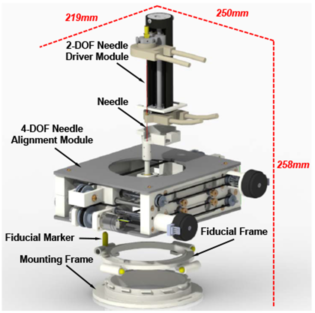
Exploded CAD model of the 6-DOF body-mounted pain injection robot, showing the major modules and its overall dimension at the home position.
From the perspective of materials, this robotic assistant should be compatible with MRI environment and lightweight while maintaining sufficient structural stiffness. Based on the classification of the American Society for Testing and Materials (ASTM F2503) [22], the major body of the robot is built with MR-Safe 3D-printed ABS plastic. MR-Conditional aluminum is used for components which require high structural stiffness, such as needle guide, universal joint, linear guides and lead screws as described in Sec. III. From the perspective of actuators and positioning sensors, nonmagnetic piezoelectric actuators (Piezo LEGS LR5012C, PiezoMotor AB, Sweden, and USR60-S4N, Shinsei Corp., Japan) and optical encoders (ET4-500, US Digital, USA), which have proved to be conditionally compatible with the MRI environment in our preceding work [23], [24], are adopted in this study. The key mechanical design specifications are summarized in Table I, which are proposed based on the anatomical structures of the lumbar spine [25]–[27] and through consultation with our clinical collaborators.
TABLE I.
Main Robot Mechanical Design Specifications
| 4-DOF Needle Alignment Module | Workspace | 80 mm diameter |
| Positioning Accuracy | 1 mm | |
| Orientation (Rx, Ry) | ± 25° | |
| Orientation Accuracy | 1° | |
| Stiffness | 0.5 mm | |
| 2-DOF Needle Driver Module | Insertion Depth | 100 mm |
| Insertion Accuracy | 0.5 mm | |
| Rotation | ± 180° | |
| Rotation Accuracy | 5° | |
| Robotic Assistant | Weight | 1.5 kg |
| Materials | MR-Conditional | |
| DOFs | 6 |
B. 4-DOF Needle Alignment Module
According to the design requirements, the 4-DOF needle alignment module is devised to provide 2-DOF translation and 2-DOF orientation, allowing placing of the needle within an 80 mm diameter cylinder at an orientation of up to 25°, which is sufficient for the low back pain injection. It is designed with two identical 2-D plane translation stages, which are connected via a needle guide with an universal joint on the bottom stage and a ball joint on the top stage as shown in Fig. 3. For each stage, the axial translation is driven by a Shinsei motor through a parallel-coupled lead screw mechanism and the lateral translation is actuated by a Piezo motor via a timing belt mechanism. Custom developed optical limit switches using opto-interrupter (RPI-221, ROHM Semiconductor, Japan) are attached to the end of each axis for robot position initialization.
Fig. 3.
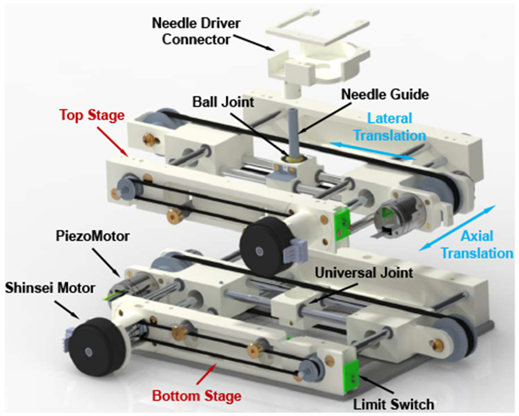
Exploded CAD model of the 4-DOF needle alignment module, showing the major components and translational motions.
As demonstrated in Fig. 2, a fiducial frame, consisted of four high-contrast MRI-visible fluid markers (MR-Spots, Beekley Corp., CT), is mounted on the bottom stage for robot registration, as described in Sec. IV-C. A mounting frame is devised to mount the robot firmly to the patient with straps, and its location can be adjusted according to the treatment region.
C. 2-DOF Remotely Actuated Needle Driver Module
In our previous study, we developed a novel remotely actuated needle driving device with beaded chain transmission [20]. In this study, we adopted the design with improved stiffness as well as increased actuation torque, and integrated it with the 4-DOF needle alignment module. The needle driver module is designed to provide 2-DOF motion (shown in Fig. 4), i.e. needle insertion (100 mm) and rotation (±180°), and is driven by an actuation box through a 1.2 m long beaded chain transmission. The actuation box (shown in Fig. 5), containing all the electronic components, is placed on the end of the scanner table about 1 m away from the isocenter of the scanner bore; therefore, it can minimize the noise during the imaging as well as reduce the weight and dimension on the patient side. The needle driver can be operated in the manual or motorized mode by disengaging or engaging the gear transmission of the actuation unit; thus, it can increase the safety in case of motors fails as well as facilitate the learning curve since the clinicians can manipulate the needle manually. To improve the safety, an insertion depth indicator and mechanical stopper are designed on the insertion actuation unit, which has synchronized motion with the needle insertion by using a mechanically coupled lead-screw mechanism. Compared to the previous study [20], the stiffness of the needle driver is increased by adding a cylindrical case around the needle driver. We also replaced the PiezoMotor of the needle insertion with a more powerful Shinsei motor and increased the gear ratio to 5:3 (driven : drive) to increase the insertion torque, which would be beneficial for the clinical application, especially for puncturing stiff tissues such as skin.
Fig. 4.
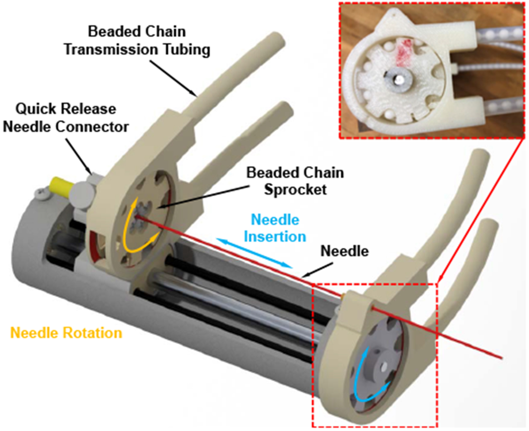
CAD model of the 2-DOF needle driver module, showing the major components and motions. Inset: prototype assembly of the beaded chain, sprocket, and nylon tubing.
Fig. 5.
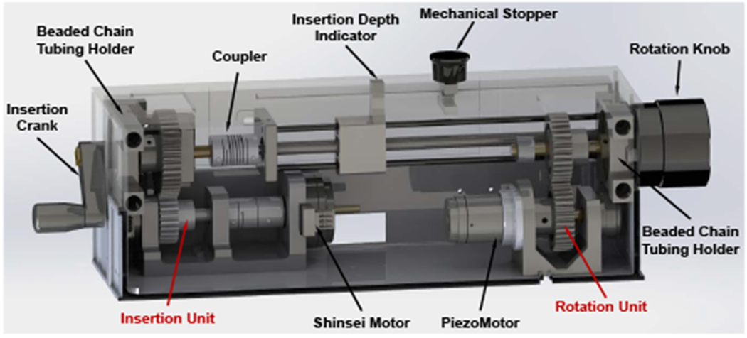
CAD model of the needle driver actuation box, showing the insertion unit and rotation unit. The presented setup is the motorized mode, the gears are engaged. Once the upper box is lifted up, the gears will be disengaged and switch to the manual mode.
The overall dimension of the robotic assistant is 219 mm x 250 mm x 258 mm and the weight is 1.5 kg, which is considered to be compact and lightweight enough to be attached to the patient’s lower back.
III. FINITE ELEMENT ANALYSIS
To assure that the proposed robotic assistant is able to sustain high precision needle placement under various loads, the stiffness and strength of the mechanism are studied using finite element analysis (FEA) method. In our previous study, the force and torque exerted by the needle driving device in static status and in dynamics status during the insertion into a phantom were measured [28]. In this study, the measured maximum force and torque in each direction (Fx: 0.932 N, Fy: 1.536 N, Fz: 2.586 N, Tx: 0.498 Nm, Ty: 0.135 Nm, Tz: 0.447 Nm) are applied on the 4-DOF needle alignment module with a safety factor of two to perform the analysis. As depicted in Sec. II-A, the majority of the mechanism is made of ABS (Young’s modulus 2 GPa, and yield stregth 40 MPa), and the needle guide, universal joint, linear guides, lead screws are made of aluminum 6061 (Young’s modulus 68.9 GPa, and yield stregth 276 MPa). The needle guide is the component that connects the needle driver module and needle alignment module, and it is supported by the bottom stage and top stage. To simulate the loads on the needle guide, 6-DOF force/torque was applied on the end which connects to needle driver, while the other end which connects to the universal joint and ball joint was constrained by the mechanism. As demonstrated in Fig. 6, the maximum deformation of the needle alignment module under vertical force is 0.0104 mm, under lateral force is 0.0065 mm, under frontal force is 0.0145 mm, under 3-DOF torque is 0.4155 mm, and under 6-DOF force/torque is 0.0196 mm. The maximum stress is 4.253 MPa, which is significantly smaller than the yield strength of aluminum and ABS. Therefore, the results of FEA indicate that the robot can afford sufficient stiffness and strength under various loads.
Fig. 6.
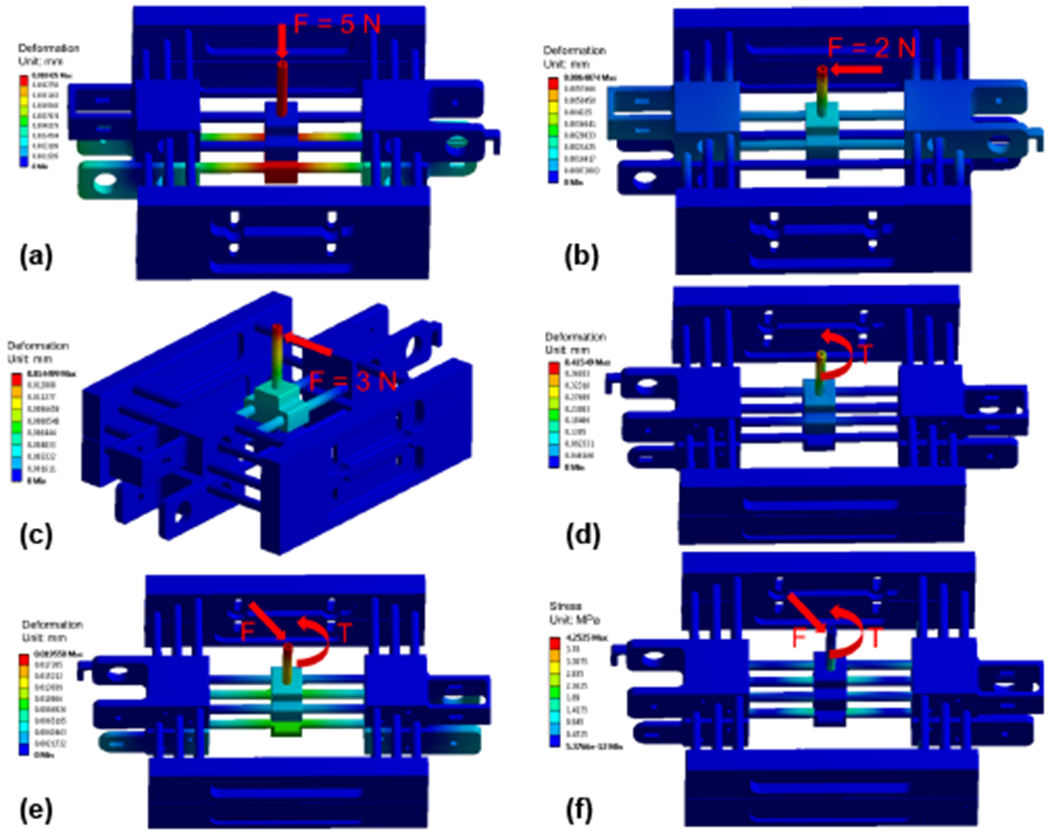
FEA of the needle alignment module indicates the deformation under vertical force (a), lateral force (b), frontal force (c), 3-DOF torque (d), 6-DOF force/torque (e), and the stress under 6-DOF force/torque (f).
IV. ROBOT KINEMATICS
A. Forward Kinematics
The forward kinematics is to solve for the needle tip position and needle axis vector, given the joint variables of the 4-DOF needle alignment module and the needle insertion depth. Note that, the needle rotation is an independent control variable for steering the needle to generate a curved trajectory, which is not considered in this study. As shown in Fig. 7, the robot base frame FBase (non-moving frame) is attached to the bottom stage, with the origin OBase = (xbase, ybase, zbase) defined at the center of universal joint, x-axis aligned with the lateral translation, y-axis aligned with the axial translation, and z-axis obtained based on the right-hand rule. The bottom stage frame FBot (moving frame) is attached to the bottom stage, with its origin Ob defined at the same location as the base frame FBase. Likewise, the top stage frame FTop (moving frame) is attached to the top stage, with its origin Ot defined at the center of ball joint and x-y-z axes aligned with the robot base frame FBase. Given the joint variables xb, yb, xt, yt, the origins of both bottom and top stages can be found: Ob = (xb, yb, 0) and Ot = (xt, yt, −H) where H is the constant distance between the two stages. Hence, given the needle insertion depth l, the needle axis vector V and needle tip position P can be solved as:
| (1) |
| (2) |
Fig. 7.
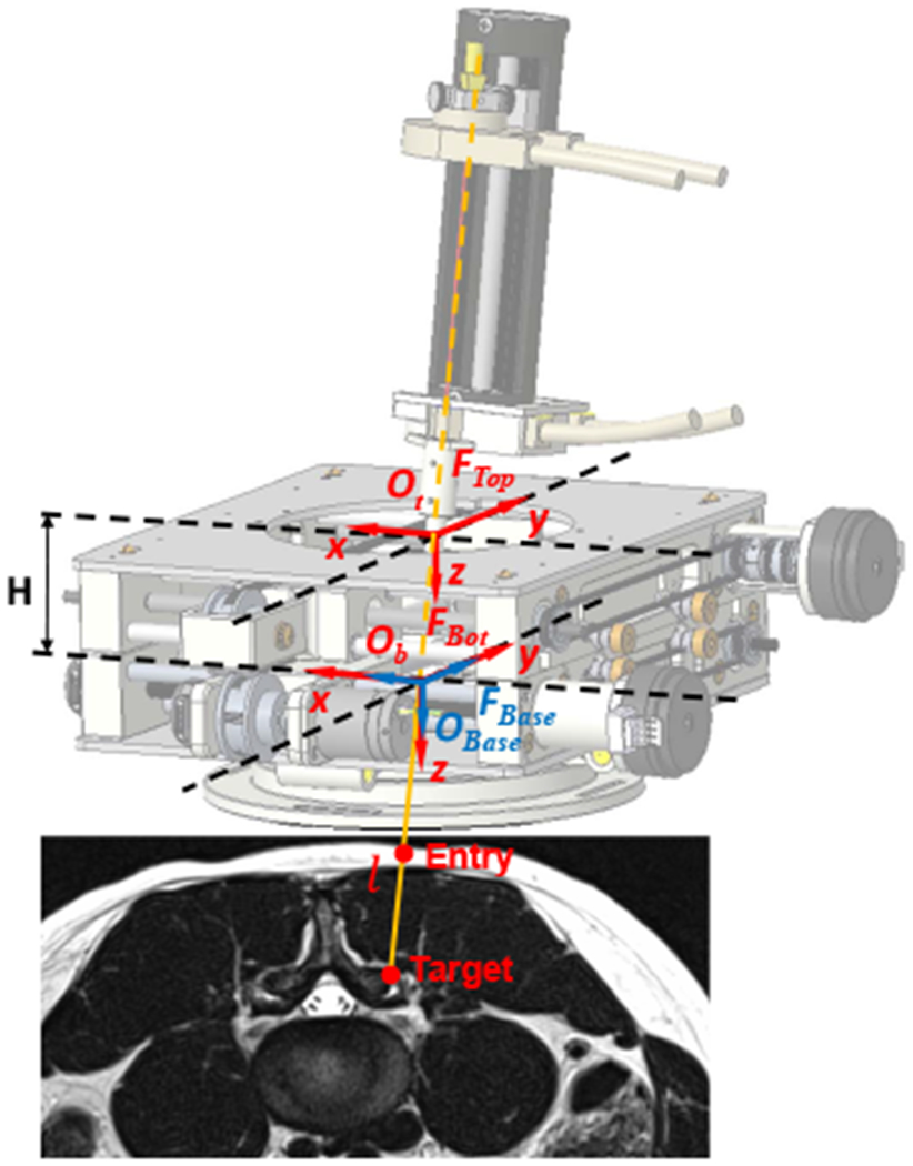
Coordinate frame assignment of the robotic assistant, overlaid on an MR image of lumbar spine. The robot base frame FBase (non-moving frame) and bottom stage frame FBot (moving frame) are defined at the center of universal joint of the bottom stage, and the top stage frame FTop (moving frame) is attached to the center of ball joint. The target and entry points are determined in the intraoperative images.
B. Inverse Kinematics
The inverse kinematics is to solve for joint variables of the 4-DOF needle alignment module and the needle insertion depth, given the needle tip position and needle axis vector. The desired target Ptarget and entry point Pentry are determined in the intraoperative image. Hence, the needle tip position P = (Px, Py, Pz) and needle axis vector V = (Vx, Vy, Vz) can be solved as P = Ptarget and V = Ptarget − Pentry. According to the geometric configuration of the two stages, the origin of the bottom frame Ob and the top frame Ot can be solved as,
| (3) |
| (4) |
The insertion depth l is determined as the distance between the needle tip P and the origin of bottom frame Ob, and therefore it can be solved as,
| (5) |
C. Registration
As depicted in Sec. II-B, a fiducial frame is attached to the 4-DOF needle alignment module to register the robot to the scanner’s RAS (Right, Anterior, Superior) coordinate system. Images of the fiducial frame are obtained to solve the registration transform utilizing line marker registration (LMR) method, which has reported accuracy of 1.00±0.73 mm and 1.41 ± 1.06° [29], and therefore the fiducial frame pose in scanner’s RAS coordinate system can be obtained. Hence, the 6-DOF needle pose in the image space can be solved through the transformation chain, written as:
| (6) |
Where is the needle tip pose with respect to the RAS coordinate system. is the needle tip pose represented in the base frame, defined by the kinematics. is the constant offset from the fiducial frame to the base frame, determined by the mechanism design. is the fiducial frame pose represented in the RAS coordinate system, obtained from the registration.
V. EXPERIMENTS AND RESULTS
A. Free Space Positioning Accuracy Assessment
The system accuracy was evaluated in free space with an optical tracking system (OTS) (NDI Polaris Spectra, Canada). A 6-DOF tracking frame was attached to the needle driver module, and a 6-DOF reference frame was mounted on the same platform with known offset from the robot base, as demonstrated in Fig. 8. The 6-DOF actual needle pose was measured as the pose of tracking frame with respect to the reference frame. The actual tip positions, as determined via the OTS, are registered to desired targets with point cloud based registration to isolate the robot accuracy from registration related errors in the experiment. Three metrics were utilized to analyze the positioning accuracy: needle tip position error (x, y, z), insertion angle error (Rx, Ry), and rotation angle error (Rz). The Needle tip position error is defined as the distance from the actual needle tip position to the desired target. Insertion angle error is determined as an angular error between the actual needle insertion angle and the planned needle insertion angle. As mentioned in Sec. IV, needle rotation is an independent control variable, and therefore the rotation angle error is measured independently as the difference between the desired angle and actual angle.
Fig. 8.
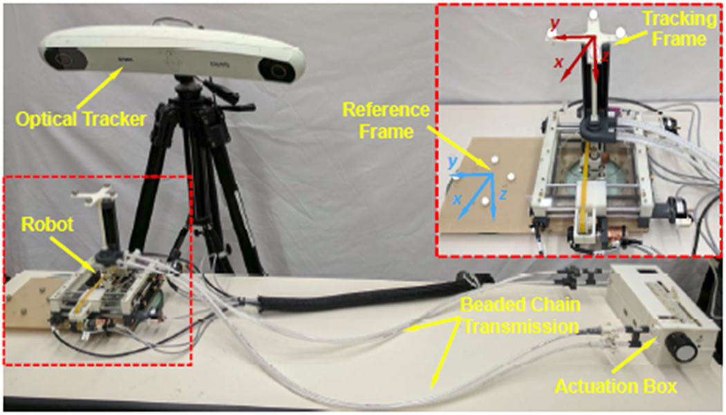
Experimental setup of free space positioning accuracy assessment with an optical tracking system. Inset: reference frame and tracking frame assignment.
The experiment was performed in the order as the robot was first initialized at the home position (H), and then proceeded to 12 target poses (T1…T12), which were selected at three comers across the workspace with various orientations. This whole procedure was repeated 10 times. The experiment results are summarized in Table II, demonstrating that the mean absolute error (MAE) of tip position to be 0.99±0.46 mm and insertion angle error to be 0.99±0.65°. The MAE of the position and orientation in each axis are x-axis 0.60±0.73 mm, y-axis 0.45±0.60 mm, z-axis 0.49±0.55 mm, Rx-axis 0.81 ± 1.08°, and Ry-axis 0.41 ± 0.36°. The rotation angle error was measured independently at the home position, by choosing four target angles (−90°, −180°, 90°, 180°) and repeated five times. The MAE of the rotation angle Rz is 1.19 ± 1.40°. The results indicate sufficient accuracy and repeatability of the mechanical system in free space.
TABLE II.
Free Space Positioning Accuracy Assessment Results.
| NO | Target (mm-deg) | ‖Error‖(STH) (mm-deg) | ||||||||||
|---|---|---|---|---|---|---|---|---|---|---|---|---|
|
| ||||||||||||
| X | Y | Z | Rx | Ry | X | Y | Z | ‖XYZ‖ | Rx | Ry | ‖RxRy‖ | |
| H | 0.00 | 0.00 | 0.00 | 0.00 | 0.00 | 0.39(0.15) | 0.07(0.10) | 0.64(0.02) | 0.77(0.08) | 0.58(0.12) | 0.36(0.15) | 0.70(0.13) |
| T1 | −20.00 | 0.00 | 0.00 | 0.00 | 0.00 | 0.53(0.14) | 0.15(0.08) | 0.86(0.02) | 1.03(0.07) | 0.50(0.10) | 0.32(0.15) | 0.60(0.13) |
| T2 | −20.00 | 0.00 | −70.00 | 0.00 | 0.00 | 0.23(0.10) | 0.32(0.21) | 0.09(0.03) | 0.44(0.14) | 0.61(0.10) | 0.23(0.19) | 0.67(0.14) |
| T3 | −20.00 | 18.12 | −67.61 | 15.00 | 0.00 | 0.98(0.10) | 0.68(0.13) | 0.46(0.04) | 1.28(0.11) | 2.43(0.20) | 0.27(0.17) | 2.45(0.19) |
| T4 | −38.12 | 0.00 | −67.61 | 0.00 | 15.00 | 1.43(0.10) | 0.96(0.12) | 0.30(0.06) | 1.75(0.11) | 0.16(0.19) | 0.16(0.14) | 0.26(0.08) |
| T5 | 20.00 | 20.00 | 0.00 | 0.00 | 0.00 | 0.49(0.16) | 0.22(0.08) | 0.47(0.03) | 0.73(0.12) | 0.82(0.14) | 0.50(0.17) | 0.98(0.10) |
| T6 | 20.00 | 20.00 | −70.00 | 0.00 | 0.00 | 0.15(0.20) | 0.16(0.14) | 0.49(0.04) | 0.57(0.14) | 0.21(0.21) | 0.42(0.22) | 0.48(0.23) |
| T7 | 20.00 | 38.12 | −67.61 | 15.00 | 0.00 | 0.95(0.08) | 0.34(0.18) | 0.15(0.07) | 1.03(0.10) | 1.77(0.37) | 0.21(0.20) | 1.79(0.36) |
| T8 | 38.12 | 20.00 | −67.61 | 0.00 | −15.00 | 1.00(0.25) | 1.03(0.41) | 1.09(0.09) | 1.86(0.24) | 0.42(0.48) | 0.66(0.21) | 0.86(0.30) |
| T9 | 20.00 | −20.00 | 0.00 | 0.00 | 0.00 | 0.17(0.14) | 0.08(0.10) | 0.43(0.03) | 0.49(0.06) | 0.84(0.09) | 0.32(0.15) | 0.91(0.11) |
| T10 | 20.00 | −20.00 | −70.00 | 0.00 | 0.00 | 0.08(0.12) | 0.39(0.12) | 0.53(0.04) | 0.68(0.05) | 0.22(0.09) | 0.31(0.18) | 0.40(0.17) |
| T11 | 20.00 | −38.12 | −67.61 | −15.00 | 0.00 | 0.60(0.24) | 0.90(0.45) | 0.38(0.16) | 1.19(0.42) | 1.68(0.28) | 0.78(0.19) | 1.87(0.23) |
| T12 | 38.12 | −20.00 | −67.61 | 0.00 | −15.00 | 0.77(0.12) | 0.61(0.06) | 0.42(0.04) | 1.08(0.06) | 0.25(0.08) | 0.83(0.18) | 0.87(0.18) |
|
| ||||||||||||
| MAE(STD) | 0.60(0.73) | 0.45(0.60) | 0.49(0.55) | 0.99(0.46) | 0.81(1.08) | 0.41(0.36) | 0.99(0.65) | |||||
B. Qualitative Imaging Quality Validation
In our prior study of a body-mounted robot for shoulder arthrography, which is built with similar materials as the robot reported herein, the effect of the robot on the imaging quality have been evaluated through quantitative geometric distortion analysis and signal-to-noise ratio based analysis [24], and magnetically induced displacement force and torque measurement [30]. In this study, to evaluate the effect of the system on the imaging quality of human lumbar spine anatomy, qualitative imaging quality validation was carried out on a human volunteer. T2-weighted blade respiratory gating imaging protocol (TE: 129 ms, TR: 7317 ms, flip angle: 144°, slice thickness: 3 mm, pixel spacing: 0.94 mm x 0.94 mm) was performed on a human volunteer to attenuate the respiratory motion artifact. The imaging was firstly performed on the volunteer with only mounting frame attached (baseline), as shown in Fig. 9, and then with the robot attached to the back, as illustrated in Fig. 1. Comparing the images of varying configurations, minimal visible degradation of image quality was observed in the lumbar spine anatomy between the baseline and robot present, as demonstrated in Fig. 10. Note that, even though respiratory motion artifact compensation imaging protocol was utilized, minimal respiratory motion artifacts were still observed on both images of baseline and robot present. These images were reviewed by our clinical collaborator and the image quality was confirmed to be sufficient for lumbar spinal injections.
Fig. 9.
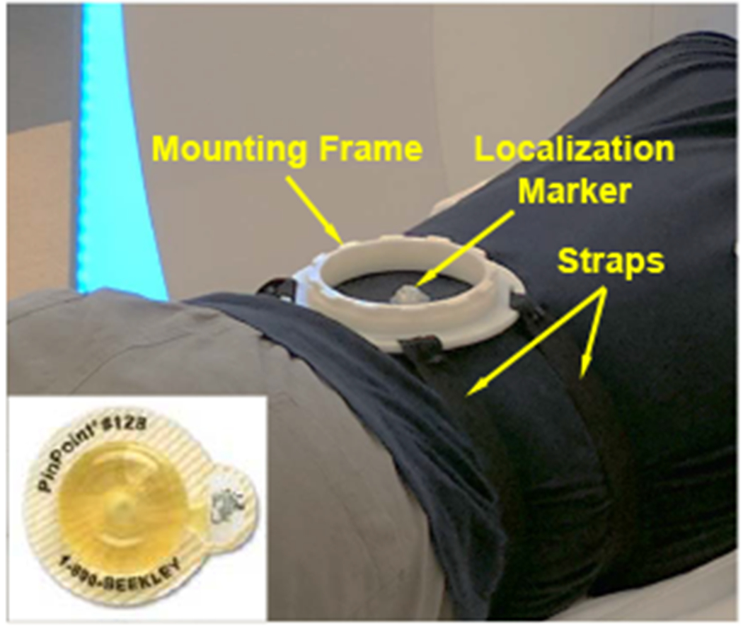
Experiment setup of the baseline for qualitative imaging quality validation study, showing only the mounting frame was attached to the volunteer. Inset: a localization marker was attached to the volunteer as a reference for the mounting stability study.
Fig. 1.
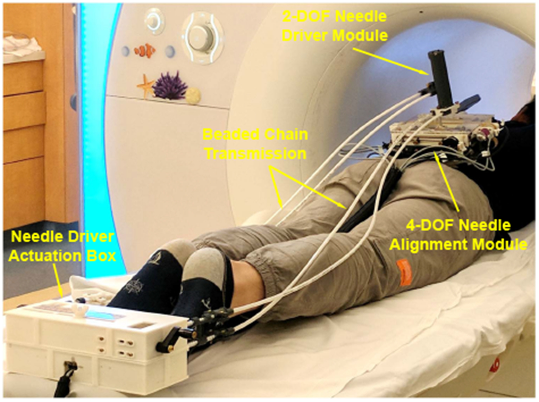
System setup of the robotic assistant inside an MRI scanner. A volunteer was placed on the scanner table in prone position and the robot was attached to the back using straps. The 2-DOF needle driver was remotely actuated through beaded chain transmission by the actuation box placed at the end of the table.
Fig. 10.
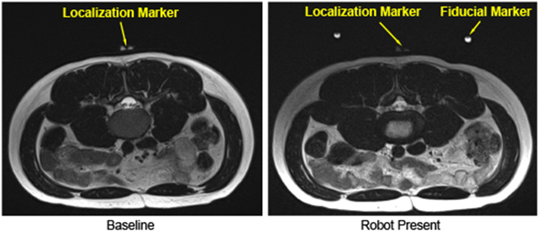
Qualitative imaging quality comparison. T2-weighted blade respiratory gating images were taken in the lumbar spine region with two configurations: no robot inside the scanner (left), and robot attached to the back (right).
C. Mounting Stability Evaluation
To investigate the stability of the mounting mechanism, an assessment study was performed on a human volunteer with the same aforementioned setup, as shown in Fig. 1. An MRI visible localization marker (PinPoint 128, Beekley Corp., CT) was attached to the back of volunteer within the workspace of the robot, as shown in Fig. 9, to detect the displacement between the robot and volunteer. T2-weighted blade respiratory gating imaging protocol was performed to acquire the positions of localization marker and robot in the MR image space. The 3D position of the localization marker with respect to the robot base frame was determined based on the LMR method, as depicted in Sec. IV-C. The volunteer mounted with the robot was moved in and out of the scanner five times, acquiring five sets of images. This process was repeated at two different mounting locations. Hence, two mounting locations with five sets of images at each location were performed. The position of the localization marker with respect to the robot frame was calculated at each imaging, and the standard deviation (STD) of the position variations was utilized as the metric to assess the mounting stability. The results, as summarized in Table. III, reveal that the 3D position variation of the localization marker with respect to the robot frame is less than 0.7 mm. The main variation is along the z-axis, i.e. the needle insertion axis, which is caused by the respiratory motion and can be compensated by adjusting the needle insertion depth under intraoperative MRI-guidance.
TABLE III.
Experiment Results of Mounting Stability Assessment
| NO | Mounting Location 1 (mm) | Mounting Location 2 (mm) | ||||||
|---|---|---|---|---|---|---|---|---|
|
| ||||||||
| x | y | z | ‖xyz‖ | x | y | z | ‖xyz‖ | |
| 1 | −0.47 | 4.19 | 32.01 | 32.29 | 0.71 | 5.96 | 31.98 | 32.54 |
| 2 | −0.47 | 4.04 | 32.21 | 32.47 | 0.74 | 6.06 | 33.11 | 33.66 |
| 3 | −0.11 | 4.85 | 31.58 | 31.95 | 0.27 | 6.49 | 33.61 | 34.24 |
| 4 | −0.46 | 4.58 | 31.43 | 31.76 | 0.25 | 6.45 | 32.69 | 33.32 |
| 5 | −0.05 | 4.95 | 30.58 | 30.98 | 0.58 | 6.26 | 31.94 | 32.55 |
|
| ||||||||
| STD | 0.19 | 0.36 | 0.57 | 0.52 | 0.21 | 0.21 | 0.65 | 0.65 |
VI. DISCUSSION AND CONCLUSIONS
This paper reports the development of a 6-DOF fully actuated body-mounted robotic assistant for MRI-guided low back pain injection to eliminate the radiation exposure of conventional X-ray guided procedures. The robot is devised with a lightweight and compact structure that can be directly attached to the patient; minimizing the effects of patient motion. The system targeting accuracy was evaluated in free space, demonstrating the needle position error to be 0.99 ± 0.46 mm, insertion angle error to be 0.99 ± 0.65°, rotation angle error to be 1.19 ± 1.40°. This prototype was mainly built with 3D printed ABS plastic materials for rapid feasibility validation and initial accuracy assessment. Fabrication errors and plastic deformation resulted in imprecise alignment of the joint axes, deformation of the components, and variation of the center of universal joint. These are to be solved in the next design iteration, including replacing the 3D printed plastic materials with high precision machined Ultem to improve the stiffness and accuracy. Qualitative imaging quality validation was conducted, verifying that the imaging degradation caused by the system was minimal and should not affect the procedure. The results of mounting stability study indicate that the proposed body-mounted mechanism can attenuate the effect of patient motion by moving with the patient. In future work, we plan to extend the work to evaluate the system thoroughly with realistic phantom and cadaver studies under real-time MRI-guidance with regard to the system accuracy and clinical workflow.
Acknowledgments
This work was funded by National Institute of Health grant R01 EB025179
References
- [1].“National institute of neurological disorders and stroke: Low back pain fact sheet.” https://www.ninds.nih.gov/Disorders/Patient-Caregiver-Education/Fact-Sheets/Low-Back-Pain-Fact-Sheet, 2019.
- [2].Fritz J, Thomas C, Clasen S, Claussen CD, Lewin JS, and Pereira PL, “Freehand real-time mri-guided lumbar spinal injection procedures at 1.5 t: feasibility, accuracy, and safety,” American Journal of Roentgenology, vol. 192, no. 4, pp. W161–W167, 2009. [DOI] [PubMed] [Google Scholar]
- [3].Carrino JA, Morrison WB, Parker L, Schweitzer ME, Levin DC, and Sunshine JH, “Spinal injection procedures: volume, provider distribution, and reimbursement in the us medicare population front 1993 to 1999,” Radiology, vol. 225, no. 3, pp. 723–729, 2002. [DOI] [PubMed] [Google Scholar]
- [4].Smith KA and Carrino J, “Mri-guided interventions of the musculoskeletal system,” Journal of Magnetic Resonance Imaging: An Official Journal of the International Society for Magnetic Resonance in Medicine, vol. 27, no. 2, pp. 339–346, 2008. [DOI] [PubMed] [Google Scholar]
- [5].Li G, Su H, Cole G, Shang W, Harrington K, Camilo A, Pilitsis JG, and Fischer GS, “Robotic System for MRI-Guided Stereotactic Neurosurgery,” Biomedical Engineering, IEEE Transactions on, vol. 62, no. 4, pp. 1077–1088, 2015. [DOI] [PMC free article] [PubMed] [Google Scholar]
- [6].Jun C, Lim S, Wolinsky J-P, Garzon-Muvdi T, Petrisor D, Cleary K, and Stoianovici D, “Mr safe robot assisted needle access of the brain: preclinical study,” Journal of Medical Robotics Research, vol. 3, no. 01, p. 1850003, 2018. [Google Scholar]
- [7].Kim Y, Cheng SS, Diakite M, Gullapalli RP, Simard JM, and Desai JP, “Toward the development of a flexible mesoscale mri-compatible neurosurgical continuum robot,” IEEE Transactions on Robotics, vol. 33, no. 6, pp. 1386–1397, 2017. [DOI] [PMC free article] [PubMed] [Google Scholar]
- [8].Lwu S and Sutherland GR, “The development of robotics for interventional mri,” Neurosurgery Clinics of North America, vol. 20, no. 2, pp. 193–206, 2009.19555882 [Google Scholar]
- [9].Stoianovici D, Kim C, Petrisor D, Jun C, Lim S, Ball MW, Ross A, Macura KJ, and Allaf ME, “Mr safe robot, fda clearance, safety and feasibility of prostate biopsy clinical trial,” IEEE/ASME Transactions on Mechatronics, vol. 22, no. 1, pp. 115–126, 2017. [DOI] [PMC free article] [PubMed] [Google Scholar]
- [10].Su H, Shang W, Cole G, Li G, Harrington K, Camilo A, Tokuda J, Tempany CM, Hata N, and Fischer GS, “Piezoelectrically actuated robotic system for mri-guided prostate percutaneous therapy,” IEEE/ASME Transactions on Mechatronics, vol. 20, no. 4, pp. 19201932, 2015. [DOI] [PMC free article] [PubMed] [Google Scholar]
- [11].Patel NA, Li G, Shang W, Wartenberg M, Heffter T, Burdette EC, Iordachita I, Tokuda J, Hata N, Tempany CM, and Fischer GS, “System Integration and Preliminary Clinical Evaluation of a Robotic System for MRI-Guided Transperineal Prostate Biopsy,” Journal of Medical Robotics Research, vol. 4, no. 1, pp. 1–14, 2018. [DOI] [PMC free article] [PubMed] [Google Scholar]
- [12].Song S, Hata N, Iordachita I, Fichtinger G, Tempany C, and Tokuda J, “A workspace-orientated needle-guiding robot for 3T MRI-guided transperineal prostate intervention: evaluation of in-bore workspace and MRI compatibility,” The International Journal of Medical Robotics and Computer Assisted Surgery, vol. 9, no. 1, pp. 67–74, 2013. [DOI] [PMC free article] [PubMed] [Google Scholar]
- [13].Krieger A, Song S, Cho NB, Iordachita II, Guion P, Fichtinger G, and Whitcomb LL, “Development and evaluation of an actuated MRI-compatible robotic system for MRI-guided prostate intervention,” Mechatronics, IEEE/ASME Transactions on, vol. 18, no. 1, pp. 273284, 2013. [DOI] [PMC free article] [PubMed] [Google Scholar]
- [14].Yang B, Roys S, Tan U-X, Philip M, Richard H, Gullapalli RP, and Desai JP, “Design, development, and evaluation of a master–slave surgical system for breast biopsy under continuous mri,” The International journal of robotics research, vol. 33, no. 4, pp. 616630, 2014. [DOI] [PMC free article] [PubMed] [Google Scholar]
- [15].Chan KG, Fielding T, and Anvari M, “An image-guided automated robot for mri breast biopsy,” The International Journal of Medical Robotics and Computer Assisted Surgery, vol. 12, no. 3, pp. 461–477, 2016. [DOI] [PubMed] [Google Scholar]
- [16].Wu FY, Torabi M, Yamada A, Golden A, Fischer GS, Tuncali K, Frey DD, and Walsh C, “An mri coil-mounted multi-probe robotic positioner for cryoablation,” 2013. [Google Scholar]
- [17].Hata N, Song S-E, Olubiyi O, Arimitsu Y, Fujimoto K, Kato T, Tuncali K, Tani S, and Tokuda J, “Body-mounted robotic instrument guide for image-guided cryotherapy of renal cancer,” Medical physics, vol. 43, no. 2, pp. 843–853, 2016. [DOI] [PMC free article] [PubMed] [Google Scholar]
- [18].Hungr N, Bricault I, Cinquin P, and Fouard C, “Design and validation of a ct-and mri-guided robot for percutaneous needle procedures,” IEEE transactions on robotics, vol. 32, no. 4, pp. 973–987, 2016. [Google Scholar]
- [19].Walsh CJ, Hanumara NC, Slocum AH, Shepard J-A, and Gupta R, “A patient-mounted, telerobotic tool for ct-guided percutaneous interventions,” Journal of Medical Devices, vol. 2, no. 1, p. 011007, 2008. [Google Scholar]
- [20].Wu D, Li G, Patel N, Yan J, Monfaredi R, Cleary K, and Iordachita I, “Remotely actuated needle driving device for mri-guided percutaneous interventions,” in 2019 International Symposium on Medical Robotics (ISMR), pp. 1–7, IEEE, 2019. [DOI] [PMC free article] [PubMed] [Google Scholar]
- [21].Li G, Patel NA, Hagemeister J, Yan J, Wu D, Sharma K, Cleary K, and Iordachita I, “Body-mounted robotic assistant for mri-guided low back pain injection,” International Journal of Computer Assisted Radiology and Surgery, pp. 1–11, 2019. [DOI] [PMC free article] [PubMed] [Google Scholar]
- [22].“Standard practice for marking medical devices and other items for safety in the magnetic resonance environment.” https://www.astm.org/Standards/F2503.htm, 2013. [DOI] [PubMed]
- [23].Eslami S, Shang W, Li G, Patel N, Fischer GS, Tokuda J, Hata N, Tempany CM, and Iordachita I, “In-bore prostate transperineal interventions with an MRI-guided parallel manipulator: system development and preliminary evaluation,” The International Journal of Medical Robotics and Computer Assisted Surgery, 2015. [DOI] [PMC free article] [PubMed] [Google Scholar]
- [24].Monfaredi R, Iordachita I, Wilson E, Sze R, Sharma K, Krieger A, Fricke S, and Cleary K, “Development of a shoulder-mounted robot for mri-guided needle placement: phantom study,” International journal of computer assisted radiology and surgery, vol. 13, no. 11, pp. 1829–1841, 2018. [DOI] [PMC free article] [PubMed] [Google Scholar]
- [25].Liu Y, Zhou X, Ma J, Ge Y, and Cao X, “The diameters and number of nerve fibers in spinal nerve roots,” The journal of spinal cord medicine, vol. 38, no. 4, pp. 532–537, 2015. [DOI] [PMC free article] [PubMed] [Google Scholar]
- [26].Otsuka Y, An HS, Ochia RS, Andersson GB, Orías AAE, and Inoue N, “In vivo measurement of lumbar facet joint area in asymptomatic and chronic low back pain subjects,” Spine, vol. 35, no. 8, p. 924, 2010. [DOI] [PMC free article] [PubMed] [Google Scholar]
- [27].Fyneface-Ogan S, “Anatomy and clinical importance of the epidural space,” in Epidural Analgesia-Current Views and Approaches, IntechOpen, 2012. [Google Scholar]
- [28].Wu D, Li G, Patel N, Yan J, Kim GH, Monfaredi R, Cleary K, and Iordachita I, “Remotely actuated needle driving device for mri-guided percutaneous interventions: Force and accuracy evaluation,” in 2019 41st Annual International Conference of the IEEE Engineering in Medicine and Biology Society (EMBC), pp. 1985–1989, IEEE, 2019. [DOI] [PubMed] [Google Scholar]
- [29].Tokuda J, Song S, Tuncali K, Tempany C, and Hata N, “Configurable Automatic Detection and Registration of Fiducial Frames for Device-to-Image Registration in MRI-Guided Prostate Interventions,” pp. 355–362, 2013. [DOI] [PMC free article] [PubMed] [Google Scholar]
- [30].Patel N, Yan J, Monfaredi R, Sharma K, Cleary K, and Iordachita I, “Preclinical evaluation of an integrated robotic system for magnetic resonance imaging guided shoulder arthrography,” Journal of Medical Imaging, vol. 6, no. 2, pp. 1 – 9 – 9, 2019. [DOI] [PMC free article] [PubMed] [Google Scholar]


