

Abstract
The real physiological environment of human body is complicated with different degrees and forms of dynamic loads applied to implanted medical devices due to the daily activities of the patients, which would have impacts on the degradation behaviors of magnesium alloy implants. In this work, the bio-corrosion behaviors of AZ31B magnesium alloy under alternating cyclic dynamic loads with different low frequencies (0.1–2.5 Hz) were specially investigated. It was found that the bio-degradation performances under external dynamic stressed conditions were much severer than those under unstressed conditions and static loads. The corrosion rates were generally accelerated as the rise of cyclic frequency. Hereby a numerical model for the degradation process of Mg alloy was established. The corrosion current density icorr of Mg alloy and the applied loading frequency f matches a linear relationship of ln icorr∝ f, which is the result of interactions between the cyclic alternating load and corrosive environment. This work could provide a theoretical reference and an experimental basis for further researches on the biodegradation behaviors of biomedical materials under dynamic conditions.
Keywords: Magnesium alloy, Biocorrosion, Fatigue, Frequency
Graphical abstract
Highlights
-
(1)
Biocorrosion of Mg alloy under dynamic load with different frequencies were studied.
-
(2)
A stress apparatus was designed to achieve in-situ evaluation under dynamic loads.
-
(3)
The rising dynamic loading frequency resulted in an increase in the corrosion rate.
-
(4)
Theoretical corrosion mechanism under dynamic load was systematically discussed.
-
(5)
A numerical relationship between corrosion rate and load frequency was determined.
1. Introduction
In recent years, magnesium and its alloys have attracted widespread research interests and attentions because of the good biocompatibility and unique degradability, and have shown great prospects for biomedical application, especially in the field of medical implanted devices [[1], [2], [3], [4], [5], [6], [7], [8]]. For the application of magnesium alloy in the field of biomedical implant, people are most concerned about the degradation properties. In order to study the bio-degradation behaviors of magnesium alloys, many scholars at home and abroad have done many works and in vitro degradation experiments [[9], [10], [11], [12], [13], [14], [15]].
At present, most of the researches on the degradation behavior of biodegradable magnesium alloys use in vitro static immersion tests or degradation experiments under static stress conditions to study the effects of different environment conditions [[16], [17], [18]]. However, in the real physiological environment of the human body, different degrees and forms of dynamic loads would applied to implanted medical devices in vivo due to the daily activities of the patients [[19], [20], [21]]. Recently, many scholars have studied the degradation behavior of magnesium alloys under dynamic loading environments through corrosion fatigue experiments [22,23]. Liu et al. [24] studied the corrosion fatigue of Mg-Zn-Y-Nd alloy in SBF solution and found that the fatigue corrosion behavior of magnesium alloy in SBF solution was different from that in air, which shows that the degradation behavior of magnesium alloy in the simulated physiological environment is closely related to the fatigue performance of the alloy and the external corrosive environment. Wegner et al. [25] studied the corrosion fatigue of WE43 magnesium alloy subjected to dynamic compression load at a frequency of 10 Hz in SBF solution, and found that its fatigue corrosion performance was significantly affected by the cyclic test duration. Rozali et al. [26] found that in NaCl solution, the fatigue crack growth rate of AZ61 magnesium alloy was affected by both dynamic load frequency and corrosive environment, and the crack growth law within the low frequency range was different from that under high frequency conditions. Barsom et al. [27] found that the waveform of the applied alternating load has a certain influence on the growth rate of corrosion cracks. When the cycle frequency of the dynamic load is low, the corrosive ions could have a longer action time on the magnesium alloy, and its interaction with external stress can be better reflected. These researches indicate that the degradation behaviors of magnesium alloy under dynamic stress conditions are different from that under unstressed environment or static loading conditions, and the bio-corrosion behavior of magnesium alloys under dynamic load physiological environment is worthy of further study [28,29].
In actual situation, the physiological stress environment of the human body and the frequencies of the dynamic loads under different human activities are mutative. Generally speaking, the physiological frequencies of the dynamic loadings applied on the biomedical implants in vivo are mostly low frequencies (0.5–3 Hz). For example, the loading frequencies of the dynamic stresses on the orthopedics and cardiovascular implanted devices are about 0.5–3 Hz and 0.8–2 Hz [30], respectively. However, most of the existing studies on the dynamic loading environment used corrosion fatigue experiments to study the degradation behavior of magnesium alloys [[31], [32], [33]]. In order to quickly evaluate the length of service time of magnesium alloy materials and shorten the test time in vitro, the dynamic load frequencies range set in the corrosion fatigue tests are about 5–20 Hz [[34], [35], [36], [37]]. Since the frequency of the alternating load is fairly high, the corrosion process is mainly controlled by the applied stress, and the acceleration effect of the corrosion environment on the fatigue corrosion of the magnesium alloy cannot be sufficiently explored [26,38]. Therefore, the experimental study of the bio-degradation behaviors of the magnesium alloy under low-frequency dynamic loading could simulate the actual situation in the body more realistically and convincingly.
In addition, most of the current researches on magnesium alloys under dynamic loading environments have focused on the effects of the corrosion fatigue limit and stress amplitude, while not enough attention was paid on the corrosion process of magnesium alloys during the dynamic loading cycle. Besides, there are few reports on the mechanism of the influence of dynamic load frequency on magnesium alloy corrosion, and the numerical relationship between the corrosion rate of magnesium alloy and the loading frequency still demands to be further explored.
In this work, the corrosion behaviors of AZ31B magnesium alloy immersed in Hank's balanced salt solution (HBSS) were investigated in a self-designed homemade apparatus, which was specifically designed to apply the alternating cyclic dynamic loads with different frequencies. The effects of dynamic loadings on the corrosion performances of Mg alloy were explored, and the influence of the external stress frequency on the corrosion behavior of AZ31B were further discussed. Specifically, the relationships between the corrosion rates and the dynamic frequencies were characterized by a numerical model. We hope this work could be helpful to develop new biodegradable implant materials with controllable degradation time, which can further improve the clinical applicability of degradable implant materials in human body, and provide a certain reference for evaluating the corrosion fatigue of magnesium alloys under physiological stress environment.
2. Materials and methods
2.1. Materials preparation
The AZ31B magnesium alloy used in this research was commercial standard extruded bar with a diameter of 5.5 mm (purchased from Huatai Metallic Materials Co., Ltd.). The purchased AZ31B magnesium alloy was subjected to elemental analysis with the MAXxLMF15 direct reading spectrometer, and the element compositions (wt.%) were confirmed as Al 2.74, Zn 1.27, Mn 0.21, Si 0.02 and Mg balance. The Mg alloy material was processed into test sample dimensions of Φ 5 mm × 100 mm by wire cutting. All the specimens were mechanically ground with #600, #800 and #1200 silicon carbide (SiC) paper successively and cleaned in ethanol and distilled water. Due to the dynamic loading experimental requirements, the exposure length of the sample in the corrosive solution for test was 2 cm at the middle of the specimen and the corrosion area was 3.142 cm2. The rest part was sealed with insulating tape and silicone rubber to avoid galvanic corrosion.
2.2. Corrosion media preparation
The Hank's balanced salt solution (HBSS) was chosen as the immersion fluid for this study and the chemical compositions of HBSS are listed in Table 1 [39]. The pH value of solution before experiment was adjusted to 7.40 ± 0.05 at (37 ± 0.5) °C. The volume of the immersion fluid for each sample was 500 ml. The immersion fluid was renewed every 24 h and prior to changing, the pH of the immersion solution was recorded.
Table 1.
Chemical compositions of Hank's solution (g/L).
| NaCl | KCl | KH2PO4 | MgSO4·7H2O | NaHCO3 | CaCl2 | Na2HPO4·H2O | Glucose |
|---|---|---|---|---|---|---|---|
| 8.00 | 0.40 | 0.06 | 0.20 | 0.35 | 0.14 | 0.06 | 1.00 |
2.3. Dynamic immersion tests
The self-designed homemade apparatus used for the dynamic immersion tests is shown in Fig. 1. The dynamic tensile and compressive cyclic alternating loads were applied through the consistent movement of the double-acting air cylinder.
Fig. 1.

Schematic illustration of apparatus in dynamic cyclic loading test.
The loading magnitude was regulated by the pressure of the gas and the frequency was modified by a switch-on clock. The magnitude of the loads applied to the specimen cross-section can be calculated by the following formula (1):
| (1) |
where s0 is the cross-sectional area of cylinder, σ0 is the output stress of the air compressor, s is the cross-sectional area of test sample. The predetermined stress in this work was 20 MPa and the value was further confirmed by using a stress sensor, as seen in the partial enlarged view on the right side of Fig. 1. The cyclic loading frequency involves 0.1 Hz, 0.25 Hz, 0.5 Hz, 0.75 Hz, 1 Hz, 1.5 Hz, 2 Hz, 2.5 Hz and 3 Hz. The volume of the immersion fluid is 2 L for each test.
2.4. Electrochemical characterization
Electrochemical impedance spectroscopy (EIS) tests were conducted using an electrochemical workstation (CHI604E, CH Instruments). The EIS data were measured every 2 h during the initial 12 h immersion and then after every 24 h. During the in-situ electrochemical tests, the dynamic loads were temporarily suspended and the open circuit tests (OCT) were carried out to achieve the steady state condition. The reference, counter and working electrodes were, respectively, the saturated calomel electrode (SCE), Pt electrode and the test sample. The stabilization time before the EIS test was 3600 s. The frequencies scanned from 100 kHz to 0.1 Hz and the potential amplitude was 0.01 V. Three sets of parallel experiments were conducted.
2.5. Characterization and weight loss tests
The H2CrO4 solution (200 g/L) was used to clean the corrosion products on the surface of the substrate, followed by ultrasonic cleaning with anhydrous ethanol for 5 min, and dried by air. Philips XL30 FEG field emission scanning electron microscope (SEM) was used to observe the corrosion surface morphology at an acceleration voltage of 20 kv. The elemental compositions of the corrosion products were determined by energy-dispersive spectrometry (EDS). Simultaneously, the corrosion products of the samples were analyzed by X-ray diffraction (XRD, D8-Discover, Bruker) measurements carried out with Cu Kα radiation (wavelength λ = 0.154 nm) in the range of 5–90°.
After the immersion for 24 h and 120 h, the corrosion products on the surface of the sample were removed. An electronic balance was used to measure the initial mass m0 and the weight of the sample after corrosion mt. The mass loss ratio (ω) and the mass loss rate (v) were calculated by the following equations:
| (2) |
| (3) |
where m0 is the initial mass and mt is the final mass of the test specimen, S is the immersion area and t is the immersion time. According to the requirements of the dynamic load loading device, the dimensions of specimens used for weight loss measurement were Φ 5 mm × 100 mm. The rest part of the weightless test sample except the clamping section was completely exposed to the corrosive medium, and the test area was about 6.283 cm2.
2.6. Statistical analysis
The statistical software Origin 9.0 was used for data analysis. The experimental results take the average of three parallel experiments. The data was fitted by least-squares fitting when possible. The associated error of the correlation results was estimated by the propagation of error for the parameters of the fitted lines.
3. Results
3.1. The corrosion behavior of AZ31B Mg alloy under dynamic loads
Fig. 2 shows the changes of pH values of HBSS solutions versus immersion time under the dynamic loads for the specimens. In the experiment, the pH value of the corrosive medium was measured before change of the HBSS solution every 24 h. The increase in the pH value of the solution could be attributed to the corrosion of the magnesium alloy. A higher pH value indicates the larger degradation rate of the magnesium alloy in the certain period of time (every 24 h).
Fig. 2.

The pH value of HBSS solution changes under the dynamic load of 20 MPa, (a) loading frequency between 0 and 0.75 Hz, (b) loading frequency between 1 and 2.5 Hz.
After immersion for 120 h, the pH value was about 7.7 at 0.1 Hz, while it was 7.83 at 1 Hz and 7.91 at 2.5 Hz. Commonly, it could be noticed that the pH value increase as increasing the load frequency. Moreover, the pH values of the corrosive media under different dynamic load frequency conditions slightly decreased as the immersion proceeds, which could be related to the protective effect of the corrosion product layer deposited on the surface in the later stage of the corrosion. Additionally, it could be noticed that during the predetermined immersion period, the pH values at 2.5 Hz were overall larger than 8.0, indicating the weakened protection of the corrosion product layer.
Fig. 3(a) shows the changes in the mass loss ratio (ω) and the mass loss rate (v) of magnesium alloy samples after immersion under dynamic load for 120 h. As the frequency of the applied load rises, the ω and v significantly increased. This indicates that the frequency of dynamic loading significantly influence the corrosion behavior of magnesium alloy, and a higher frequency commonly suggests a larger corrosion rate.
Fig. 3.

Corrosion behavior of Mg alloy under different loading frequency. (a) the variation of ω and v, (b) the variation of iv.
Moreover, the average corrosion current density was calculated through the mass loss rate according to Faraday's current law of electrolysis. The corrosion current density (iv) decided by v can be obtained according to the following formula [40,41]:
| (4) |
where n is the metal ion valence, F is the Faraday constant, and M is the molar mass. The variation of iv is shown in Fig. 3(b). The iv was about 0.0006 A/cm2 at 0.1 Hz, comparting to about 0.0009 A/cm2 at 1Hz and 0.0014 A/cm2 at 2.5 Hz, respectively. Since the corrosion rate of the metal is proportional to its corrosion current density, it illustrates more intuitively that the corrosion of the magnesium alloy accelerates with the increase of loading frequency.
3.2. Surface morphologies
Fig. 4 shows the metallographic microstructure of the AZ31B extruded magnesium alloy sample. Fig. 4(a) and (b) respectively show the microstructure perpendicular and parallel to the extrusion direction. It can be seen that on the cross section perpendicular to the extrusion direction, the second phase was distributed in granular form, as shown in Fig. 4(a). However, in Fig. 4(b), black band-like distribution of the second phase particles along the extrusion direction was observed.
Fig. 4.

The metallographic microstructure of AZ31B extruded magnesium alloy bar, (a) perpendicular to the extrusion direction, (b) parallel to the extrusion direction.
Fig. 5 shows the surface micro-corrosion morphologies of magnesium alloy after 120 h immersion under different load frequency conditions (0.1–2.5 Hz). It can be observed that the corrosion behavior of Mg alloy with rising frequency presents an increasingly serious trend. The exposed surface of the matrix gradually disappears, and the number of corrosion pits gradually increases, along with the depth deepens progressively. Under the dynamic load of different frequencies, the corrosion behaviors of the samples are mainly concentrated around the corrosion pits, while the surface of the substrate still maintains a certain integrity. This is due to the stress concentration phenomenon in the local area of the corrosion pit, and the corrosion ions will preferentially erode the area near the pit, resulting in the pitting area being more prone to further corrosion damage. At the same time, under the effects of cyclic alternating loads, the passivation film and the corrosion products layer are more likely to fall off the surface of the sample with the action of small vibrations, which resulted in this area will be preferentially damaged by erosion.
Fig. 5.

The microscopic corrosion morphology of Mg alloy immersed for 120 h under dynamic load of 20 MPa. (a) 0.1 Hz, (b) 0.5 Hz, (c) 1 Hz, (d) 1.5 Hz, (e) 2 Hz, (f) 2.5 Hz.
It can also be observed that there are corrosion grooves distributed along the axial direction of the sample. Since the samples used for the observation of micro-corrosion morphology were of the same parallel to the extrusion direction just as in Fig. 4(b), the elongated corrosion channels in the microscopic corrosion morphology could be related to the axially distributed second phase particles generated during the drawing process of the rod-shaped sample.
The EDS analysis result of the corrosion products and XRD diffraction results were shown in Fig. 6. As can be seen from Fig. 6(a), the elemental contents of Mg, O, Ca, and P in the corrosion products were the highest, and the contents of Al and Zn were fairly low, which inferred that the corrosion products of Al and Zn may also be present, but very few from the content. Further, XRD analysis was carried out, as shown in Fig. 6(b). It can be found that in the corrosion products, Mg(OH)2 and Mg3(PO4)2 exhibit a significant feature, while the Ca-P was generally not particularly characteristic because of the complicated structure. Combined with the EDS element analysis, it can be judged that the corrosion products were mainly formed as Mg(OH)2, Mg3(PO4)2 and the Ca-P phase complex, and there was also a very small amount of corrosion products of Al and Zn.
Fig. 6.

Corrosion product analysis after 120h immersion (a) EDS analysis result; (b) XRD component analysis result.
3.3. Electrochemical test of AZ31B Mg alloy under dynamic loads
Fig. 7 demonstrates the changes of the EIS of magnesium alloy with time under the dynamic cyclic load at different frequencies. It can be seen that at the initial stage, the impedance spectrum consists of one capacitive loop and an inductive loop in the low-frequency region, while in the mid-immersion period, a second capacitive loop appears in the high-frequency region. With the extension of the degradation time, the diameter of the capacitive loop as a whole gradually increases and then decreases. In the early stage of corrosion (0–12 h), the diameter of the capacitive loop increases rapidly, and in the later period of corrosion (24–120 h), the diameter tends to be flat, and decreased fluctuatingly. However, the inductive resistance loop changes slowly during the entire degradation process of the magnesium alloy.
Fig. 7.

The EIS nyquist plots of magnesium alloy changes with time under the dynamic load of 20 MPa (a) 0.1 Hz, (b) 0.5 Hz, (c) 1 Hz, (d) 1.5 Hz, (e) 2 Hz, (f) 2.5 Hz.
This is because with the thickening of the surface products film, the charge transfer gradually becomes difficult, resulting in an increase in the diameter of capacitive resistance loop. While in the later stage of corrosion, the corrosion behaviors of the samples are severer, the regular small vibrations make the protective film layer does not adhere well to the substrate, resulting in shedding and accelerated corrosion of the substrate. Therefore, the capacitive resistance loop will shrink in the later stage of corrosion. The higher the frequency of the applied dynamic load, the more severe the effect of this small vibration, so the capacitive loop presents the smallest diameter under the dynamic load of 2.5 Hz. The inductive loops that appeared in the Nyquist plots were related to the change of surface state. At the beginning of the experiment, due to the passivation film on the surface of the sample, and the enrichment of corrosive ions, the electrochemical environment around the surface would be in a metastable state, and the inductive loop would appear [42]. During the experiment, some intermediate unstable ions were generated [43], and the corrosion product began to gradually generate and deposit on the surface of the sample simultaneously, which would also change the surface state and cause the appearance of the inductive loops [44].
The EIS of the magnesium alloy could be further fitted by ZSimpwin software according to the equivalent circuit shown in Fig. 8 to obtain the polarization resistance (Rp). Rp reflected the kinetics of the electrode process and can be calculated by Refs. [45,46]:
| (4a) |
| (5) |
Fig. 8.

Equivalent electrical circuit. (a) Prophase of corrosion; (b) Latter stage of corrosion.
Fig. 9 reflects the change of Rp with time under different frequency dynamic loads. It can be seen that the Rp values of magnesium alloys under different dynamic loads illustrate a gradually increasing trend with the extension of the immersion time from 0 to 12 h, indicating that the generation and deposition rates of corrosion products on the surface of the magnesium alloy were higher than the dissolution and destruction rates of the surface protective film. Within 10–24 h, the Rp values of magnesium alloy have reached the maximum successively under different frequencies. During the immersion period of 24–120 h, the Rp of the samples showed a decreasing trend on the whole, and there were some fluctuations, indicating that the rates of corrosion products formation and deposition on the surface of the magnesium alloy were lower than the dissolution and destruction rates of the film. When the frequency of the dynamic load increases, the polarization resistance of the magnesium alloy sample as a whole also shows an increasing trend, and at the same time, the fluctuation of Rp value in the later stage of degradation is more obvious, indicating that higher frequency shows more significant impact to the corrosion of the magnesium alloy.
Fig. 9.

The change of the polarization resistance of magnesium alloy with time under dynamic load (a) 0.1–0.75 Hz, (b) 1–2.5 Hz.
The corrosion current density values of the Mg alloy samples at different times in the experiment could be obtained by the Rp values through conversion. The linear polarization relationship between the Rp and the corrosion current density icorr (which is decided by Rp) can be expressed by the Stern formula [16,45,47]:
| (6) |
where ba and bc are the anode and cathode Tafel constants respectively. Under the experimental conditions, ba = 0.12 and bc = 0.38. Thus the relationship between icorr and Rp is:
| (7) |
Fig. 10 shows the change of the icorr of magnesium alloy with time under the dynamic load of different frequencies. After the dynamic alternative cyclic loading and the corrosive medium act together for 24–120 h, the icorr of magnesium alloy shows a gradual increase trend. The higher the frequency applies, the greater the corrosion current density. This result is consistent with the changing pattern of iv calculated by the mass loss rate.
Fig. 10.

The changes in icorr of Mg alloys with time under dynamic loads with different frequencies.
4. Discussion
4.1. The corrosion mechanism of AZ31B Mg alloy under dynamic loads
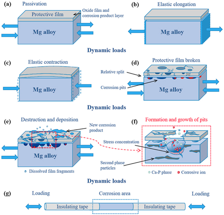
Apparently, the dynamic load would significantly influence the corrosion behaviors of magnesium alloys, and the possible mechanism was shown in Fig. 11. During immersion, a dense Mg(OH)2 passivation film will quickly form on the surface of the magnesium alloy. As the immersion proceeds, some deposition products will accumulate on the surface of the sample, as shown in Fig. 11 (a).
Fig. 11.

Schematic diagram of the corrosion mechanism of magnesium alloy under alternating cyclic axial load, (a) passivation film formation, (b) elastic tensile elongation, (c) elastic compressive contraction, (d) relative split of the film, (e) destruction and deposition of the corrosion products, (f) nucleation and growth of pitting pits, (g) magnesium alloy rod sample used for research.
Under the action of applied tensile and compressive alternating stress, the magnesium alloy rod will undergo slight elastic expansion and contraction [48], as shown in Fig. 11(b) and (c). With the function of this slight elastic expansion and contraction, the mismatch of the mechanical properties between the surface corrosion product film and the substrate would result in the accumulated damage in the production film, causing the broken and split of the protective film [49]. Thereafter, the fresh magnesium alloy substrate would be exposed to the corrosive medium, causing more serious corrosion damage, as shown in Fig. 11(d). After the corrosion product layer was destroyed, the corrosion ions in the solution can more easily react with the matrix, and the pitting pits began to nucleate and gradually grow [50], resulting in obvious local pitting, as shown in Fig. 5.
As the corrosion reaction progressed, new corrosion products would form and gradually deposit on the surface of the sample, as shown in Fig. 11(e). Additionally, it should be mentioned that the applied load would further induce stress concentration at the location of the pitting pits [51,52], which will further accelerate the formation and growth of pitting pits and corrosion cracks [17,33,36], as shown in Fig. 11(f). The higher the frequency of the load, the greater the stress value, and the more obvious the damage to the film and the acceleration of corrosion.
It is worth mentioned that during the corrosion process, the damage of the corrosion product layer did not have a fixed direction, as shown in Fig. 11(e) and (f). The damage may be manifested as flaked off or the thinning of the local corrosion product layer. After corrosive ions penetrate the protective film on the surface of the magnesium alloy, the position of the second phase particles on the surface of the substrate would be attacked more preferentially, and a micro galvanic couple would be formed between the second phase and the magnesium alloy substrate, thus the galvanic corrosion would occur. The direction of the corrosion grooves observed in the microscopic corrosion morphology were more affected by the shape and distribution of the second phase particles, which could be observed in Figs. 4 and 5.
4.2. The numerical relationship of corrosion current density and dynamic frequencies
It could be observed from Fig. 10 that an approximate primary linear relationship was present between the frequency of the external dynamic load and the ln icorr obtained by the experimental results. During one single cycle of the destruction-generation of the corrosive product layer, the corrosion current density of the micro-region of the matrix can be calculated by the following formula [[53], [54]]:
| (8) |
where i0 is the anode dissolution corrosion current density generated by exposing the surface of the new substrate, t0 is the time from the passivation film rupture to the re-generation of the passivation film, tf is the time from the passivation film generation to the passivation film rupture again, and m is the current attenuation constant.
The average value of the current density during the formation-cracking process of the passivation film is selected to represent the corrosion current density in this process [[53], [54]], which is expressed as:
| (9) |
Under the effect of the alternating cyclic load, the time required for the passivation film to rupture is much lower than its generation time. Assuming that the passivation film rupture of the micro-area on the substrate surface occurs instantaneously, it can be considered that t0 ≈ tf, and the average corrosion current density iavg ≈ i0.
The corrosion current density of the magnesium alloy can be expressed by the following formula [[53], [55], [56]]:
| (10) |
where Ea is the thermal activation energy.
At a constant temperature, the thermal activation energy of the sample under the cyclic alternating load is related to the stress magnitude and the loading frequency of the alternating load. The greater the stress value and the higher the frequency, the lower the thermal activation energy would be. The corrosion reaction rate of magnesium alloy samples would also be faster under the same external conditions [57,58]:
| (11) |
Where k is the reaction rate constant, A is the pre-exponential factor, T is the thermodynamic temperature, and R is the molar gas constant.
The process of the accelerated corrosion failure of magnesium alloy under dynamic load can be regarded as a process of energy dissipation. When undergoing a certain period of alternating stress, the corrosion damage of magnesium alloy is the macroscopic manifestation of the destruction of intercrystalline bonds. The linear cumulative damage theory assumes that the applied stress is lower than the yield strength of the material, and the influence of the large plastic deformation caused by the loading sequence can be ignored. Thereby, the equivalent stress transmitted to the sample could be considered to produce the damage and failure of the sample, which is consistent with the situation in our research. According to the linear cumulative damage theory [59,60], when the frequency of the applied dynamic loading is accelerated, the linear accumulation of energy dissipation in the magnesium alloy would also increase proportionally. The relationship between the corrosion current density and frequency of the magnesium alloy under dynamic alternating load could be expressed as follows:
| (12) |
Among them, β is the correction coefficient. Then the relationship between the corrosion current density and the load frequency of magnesium alloy under dynamic alternating load is followed ln icorr ∝ f.
Fig. 12 is the change of the theoretical and experimental values of icorr of magnesium alloy under dynamic alternating load. Due to the fairly low frequency of the alternating load applied to the test specimen, it takes a long time to show the effect of frequency on the corrosion behavior of magnesium alloy, so the values of icorr of magnesium alloy after 48–120 h immersion were selected to observe. As can be seen from Fig. 12(a) and (b), the experimental value of the corrosion current density obtained by the data of the electrochemical impedance experiment is consistent with the theoretical value of the fitted line. In order to further verify the effectiveness and reliability of this numerical relationship, the results of the weight loss experiment were analyzed to obtain the relationship between the corrosion current density iv of the weight loss method and the dynamic load frequency f, as shown in Fig. 12(c). It can be seen that the linear relationship was also compliant between the ln iv obtained by the weight loss experiment and the dynamic frequency f, which further verifies the ln i ∝ f linear relationship between the corrosion current density of magnesium alloy and the loads frequency.
Fig. 12.

The experimental and theoretical values of the corrosion current density of magnesium alloy under dynamic alternating load, (a) icorr obtained by EIS experiment of 48 h and 72 h immersion, (b) icorr obtained by EIS experiment of 96 h and 120 h immersion, (c) the average corrosion current density iv obtained by weight loss experiment.
4.3. Influence of dynamic loading and frequency on the corrosion rate of AZ31B Mg alloy
For the corrosion behavior of the magnesium alloy in HBSS, the formation of the main component Mg(OH)2 in the corrosion products has a significant effect on its corrosion process. When the magnesium alloy is anodic polarized to a higher potential in HBSS solution, the anion such as OH− adsorbed on the surface of the magnesium alloy, as well as the combination between H2O molecules and magnesium atoms are changed from an adsorption bond to a chemical bond, and Mg(OH)2 is formed on the surface as a film layer, to isolate the magnesium alloy substrate from the HBSS solution, thus to prevent the magnesium alloy from directly contacting the solution to corrosion and dissolution. On the surface of the substrate covered by the Mg(OH)2 film layer, the anodic dissolution process of the magnesium alloy is closely related to the generation and dissolution process of the Mg(OH)2 film layer. The dissolution process of the interface between the Mg(OH)2 film and the HBSS solution causes the Mg(OH)2 film to become thinner. There is a potential difference between the interface of the Mg(OH)2 film layer to the magnesium alloy substrate and the interface of the Mg(OH)2 film layer to the HBSS solution, causing the positively charged Mg2+ from the inside of the Mg(OH)2 film layer migrate to the outside of the membrane layer, or make negatively charged anions such as OH− migrate to the outside of the membrane layer to generate a new Mg(OH)2 membrane layer. The larger the electric field strength in the film layer, the faster the migration speed of cations or anions therein, and therefore the faster the new film layer is generated. Since the potential difference between the two sides of the film layer is constant under constant conditions, the thinner the film layer, the higher the electric field strength inside it. Therefore, under constant external conditions, there is a positive correlation between the corrosion current density of magnesium alloys covered with Mg(OH)2 films and the dissolution rate of Mg(OH)2 films [61].
Simultaneously, other ingredients in corrosion products, such as Mg3(PO4)2, Ca-P-phase, and small amount of corrosion products of Al and Zn would also affect the corrosion of magnesium alloy to a certain extent. Different stability and solubility of the corrosive product components would have different degrees of effects on the corrosion process. Therefore, the experimental results of the corrosion current density presented smaller fluctuations and deviate slightly from the linear relationship, as shown in Fig. 12.
Under the action of dynamic alternating cyclic load, with the increase of dynamic frequency, the destruction and dissolution rate of the film layer gradually increases, thus the deposited product cannot adhere well to the surface of magnesium alloy under the action of cyclic vibration, and the polarization resistance gradually increased to the maximum value in the early stage of corrosion and then gradually decayed, as shown in Fig. 9.
5. Conclusion
This paper mainly studied the effect of cyclic dynamic alternating stress on the bio-corrosion behavior of AZ31B magnesium alloy, and established a theoretical quantitative relationship between the degradation rates of magnesium alloy and the frequencies of the applied dynamic loads.
The results demonstrate that the cyclic dynamic tensile-compressive alternating loads would significantly accelerate the corrosion process of magnesium alloys, and the higher the applied frequency of dynamic loads, the more obvious the acceleration effect on the corrosion. Cyclic alternating loading conditions and corrosive environments have complicated interactions on the degradation behavior of magnesium alloy. Under the experimental conditions with dynamic loads, a linear numerical relationship as ln icorr ∝ f between the corrosion current density of magnesium alloy and the frequency of dynamic loads was observed. With the action of the dynamic stress, the higher the frequency of the cyclic alternating load, the more severe the corrosion fatigue process would occur in a certain period of time. Besides, it is easier for the passive film and corrosion product layer to dissolve and destroy under the dynamic loading environment. Thus the magnesium alloy is more prone to corrosion damage. This work can provide a certain theoretical and experimental basis for the design and evaluation of degradable magnesium alloy implant devices in vitro.
Data availability
The raw/processed data required to reproduce these findings cannot be shared at this time as the data also forms part of an ongoing study.
CRediT authorship contribution statement
Linyuan Han: Conceptualization, Methodology, Software, Formal analysis, Writing – original draft, Writing – review & editing. Zhenwei Zhang: Data curation, Validation, Investigation. Jianwei Dai: Investigation, Visualization, Software. Xuan Li: Conceptualization, Methodology, Writing – review & editing. Jing Bai: Resources. Zhihai Huang: Resources. Chao Guo: Resources. Feng Xue: Supervision. Chenglin Chu: Conceptualization, Supervision, Project administration.
Declaration of competing interest
There is no conflict of interest.
Acknowledgements
This research was supported by the National Natural Science Foundation of China (Grant No. 51771054), State Key Program of National Natural Science Foundation of China (Grant No. 51631003), National Key Research and Development Program of China (Grant No. 2016YFC1102402), the Open Research Fund of Jiangsu Key Laboratory for Advanced Metallic Materials (Grant No. AMM2021A01), the Opening Project of Jiangsu Key Laboratory of Advanced Structural Materials and Application Technology (Grant No. ASMA201901), Postgraduate Research&Practice Innovation Program of Jiangsu Province (Grant No. KYCX20_0091), Natural Science Foundation of Jiangsu Province (BK20181020), and the Introduction of Talent Research Fund in Nanjing Institute of Technology (YKJ201705).
Footnotes
Peer review under responsibility of KeAi Communications Co., Ltd.
References
- 1.Zhang Y., Xu J., Ruan Y.C. Implant-derived magnesium induces local neuronal production of CGRP to improve bone-fracture healing in rats. Nat. Med. 2016;22(10):1160–1169. doi: 10.1038/nm.4162. [DOI] [PMC free article] [PubMed] [Google Scholar]
- 2.Zheng Y.F., Gu X.N., Witte F. Biodegradable metals. Mater. Sci. Eng. R Rep. 2014;77:1–34. [Google Scholar]
- 3.Zhao D., Witte F., Lu F. Current status on clinical applications of magnesium-based orthopaedic implants: a review from clinical translational perspective, Biomaterials. 2017;112:287–302. doi: 10.1016/j.biomaterials.2016.10.017. [DOI] [PubMed] [Google Scholar]
- 4.Mao L., Shen L., Chen J. Enhanced bioactivity of Mg-Nd-Zn-Zr alloy achieved with nanoscale MgF2 surface for vascular stent application. ACS Appl. Mater. Interfaces. 2015;7(9):5320–5330. doi: 10.1021/am5086885. [DOI] [PubMed] [Google Scholar]
- 5.Liu Y., Zheng Y., Chen X.H. Fundamental theory of biodegradable metals—definition, criteria, and design. Adv. Funct. Mater. 2019;29(18):1805402. [Google Scholar]
- 6.Erbel R., Di Mario C., Bartunek J. Temporary scaffolding of coronary arteries with bioabsorbable magnesium stents: a prospective, non-randomised multicentre trial. The Lancet. 2007;369(9576):1869–1875. doi: 10.1016/S0140-6736(07)60853-8. [DOI] [PubMed] [Google Scholar]
- 7.Mao L., Zhou H., Chen L. Enhanced biocompatibility and long-term durability in vivo of Mg-Nd-Zn-Zr alloy for vascular stent application. J. Alloys Compd. 2017;720:245–253. [Google Scholar]
- 8.Chen Y., Xu Z., Smith C. Recent advances on the development of magnesium alloys for biodegradable implants. Acta Biomater. 2014;10(11):4561–4573. doi: 10.1016/j.actbio.2014.07.005. [DOI] [PubMed] [Google Scholar]
- 9.Witte F., Fischer J., Nellesen J. In vitro and in vivo corrosion measurements of magnesium alloys. Biomaterials. 2006;27(7):1013–1018. doi: 10.1016/j.biomaterials.2005.07.037. [DOI] [PubMed] [Google Scholar]
- 10.Witte F. Reprint of: the history of biodegradable magnesium implants: a review. Acta Biomater. 2015;(23 Suppl):S28–S40. doi: 10.1016/j.actbio.2015.07.017. [DOI] [PubMed] [Google Scholar]
- 11.Guan X., Xiong M., Zeng F. Enhancement of osteogenesis and biodegradation control by brushite coating on Mg-Nd-Zn-Zr alloy for mandibular bone repair. ACS Appl. Mater. Interfaces. 2014;6(23):21525–21533. doi: 10.1021/am506543a. [DOI] [PubMed] [Google Scholar]
- 12.Qin H., Zhao Y., An Z. Enhanced antibacterial properties, biocompatibility, and corrosion resistance of degradable Mg-Nd-Zn-Zr alloy. Biomaterials. 2015;53:211–220. doi: 10.1016/j.biomaterials.2015.02.096. [DOI] [PubMed] [Google Scholar]
- 13.Li Y., Liu L., Wan P. Biodegradable Mg-Cu alloy implants with antibacterial activity for the treatment of osteomyelitis: in vitro and in vivo evaluations. Biomaterials. 2016;106:250–263. doi: 10.1016/j.biomaterials.2016.08.031. [DOI] [PubMed] [Google Scholar]
- 14.Wu Q., Zhu S., Wang L. The microstructure and properties of cyclic extrusion compression treated Mg-Zn-Y-Nd alloy for vascular stent application, J. Mech. Behav. Biomed. Mater. 2012;8:1–7. doi: 10.1016/j.jmbbm.2011.12.011. [DOI] [PubMed] [Google Scholar]
- 15.Miao H., Huang H., Shi Y. Effects of solution treatment before extrusion on the microstructure, mechanical properties and corrosion of Mg-Zn-Gd alloy in vitro. Corrosion Sci. 2017;122:90–99. [Google Scholar]
- 16.Kirkland N.T., Birbilis N., Staiger M.P. Assessing the corrosion of biodegradable magnesium implants: a critical review of current methodologies and their limitations. Acta Biomater. 2012;8(3):925–936. doi: 10.1016/j.actbio.2011.11.014. [DOI] [PubMed] [Google Scholar]
- 17.Choudhary L., Singh Raman R.K., Hofstetter J. In-vitro characterization of stress corrosion cracking of aluminium-free magnesium alloys for temporary bio-implant applications. Mater. Sci. Eng. C Mater. Biol. Appl. 2014;42:629–636. doi: 10.1016/j.msec.2014.06.018. [DOI] [PubMed] [Google Scholar]
- 18.Bobby Kannan M., Singh Raman R.K. Evaluating the stress corrosion cracking susceptibility of Mg–Al–Zn alloy in modified-simulated body fluid for orthopaedic implant application. Scripta Mater. 2008;59(2):175–178. [Google Scholar]
- 19.Duda G.N., Schneider E., Chao E.Y.S. Internal forces and moments in the femur during walking. J. Biomech. 1997;30(9):933–941. doi: 10.1016/s0021-9290(97)00057-2. [DOI] [PubMed] [Google Scholar]
- 20.Lanyon L.E., Hampson W.G., Goodship A.E. Bone deformation recorded in vivo from strain gauges attached to the human tibial shaft. Acta Orthop. Scand. 1975;46(2):256–268. doi: 10.3109/17453677508989216. [DOI] [PubMed] [Google Scholar]
- 21.Li X., Chu C., Chu P.K. Effects of external stress on biodegradable orthopedic materials: a review. Bioact. Mater. 2016;1(1):77–84. doi: 10.1016/j.bioactmat.2016.09.002. [DOI] [PMC free article] [PubMed] [Google Scholar]
- 22.Liu Y., Liu Z., Liu L. Influence of glucose on corrosion fatigue and cytocompatibility of Mg–Zn–Zr–Y alloy. Adv. Eng. Mater. 2021:2001451. [Google Scholar]
- 23.Shen Z., Zhao M., Zhou X. A numerical corrosion-fatigue model for biodegradable Mg alloy stents, Acta Biomater. 2019;97:671–680. doi: 10.1016/j.actbio.2019.08.004. [DOI] [PubMed] [Google Scholar]
- 24.Liu M., Wang J., Zhu S. Corrosion fatigue of the extruded Mg–Zn–Y–Nd alloy in simulated body fluid. J. Magnes. Alloy. 2020;8(1):231–240. [Google Scholar]
- 25.Wegner N., Kotzem D., Wessarges Y. vol. 12. Materials (Basel); 2019. (Corrosion and Corrosion Fatigue Properties of Additively Manufactured Magnesium Alloy WE43 in Comparison to Titanium Alloy Ti-6Al-4V in Physiological Environment). 18. [DOI] [PMC free article] [PubMed] [Google Scholar]
- 26.Rozali S., Mutoh Y., Nagata K. Effect of frequency on fatigue crack growth behavior of magnesium alloy AZ61 under immersed 3.5mass% NaCl environment, Mater. Sci. Eng. A-Struct. Mater. Prop. Microstruct. Process. 2011;528(6):2509–2516. [Google Scholar]
- 27.Barsom J.M. Mechanisms of corrosion fatigue below kiscc. Int. J. Fract. Mech. 1971;7(2):163–182. [Google Scholar]
- 28.Jafari S., Harandi S.E., Singh Raman R.K. A review of stress-corrosion cracking and corrosion fatigue of magnesium alloys for biodegradable implant applications. Jom. 2015;67(5):1143–1153. [Google Scholar]
- 29.Sajuri Z.B., Umehara T., Miyashita Y. Fatigue-life prediction of magnesium alloys for structural applications. Adv. Eng. Mater. 2003;5(12):910–916. [Google Scholar]
- 30.Singh Raman R.K., Jafari S., Harandi S.E. Corrosion fatigue fracture of magnesium alloys in bioimplant applications: a review, Eng. Fract. Mech. 2015;137:97–108. [Google Scholar]
- 31.Eliezer A., Haddad J., Unigovski Y. Static and dynamic corrosion fatigue of Mg alloys used in automotive industry. Mater. Manuf. Process. 2005;20(1):75–88. [Google Scholar]
- 32.Harandi S.E., Singh Raman R.K. Appropriate mechanochemical conditions for corrosion-fatigue testing of magnesium alloys for temporary bioimplant applications. Jom. 2015;67(5):1137–1142. [Google Scholar]
- 33.Choudhary L., Raman R.K. Magnesium alloys as body implants: fracture mechanism under dynamic and static loadings in a physiological environment. Acta Biomater. 2012;8(2):916–923. doi: 10.1016/j.actbio.2011.10.031. [DOI] [PubMed] [Google Scholar]
- 34.Song Y.W., Shan D.Y., Han E.H. Electrodeposition of hydroxyapatite coating on AZ91D magnesium alloy for biomaterial application. Mater. Lett. 2008;62(17–18):3276–3279. [Google Scholar]
- 35.Gutman E.M., Eliezer A., Unigovski Y. Mechanoelectrochemical behavior and creep corrosion of magnesium alloys. Mat. Sci. Eng. a-Struct. 2001;302(1):63–67. [Google Scholar]
- 36.Choudhary L., Singh Raman R.K. Mechanical integrity of magnesium alloys in a physiological environment: slow strain rate testing based study. Eng. Fract. Mech. 2013;103:94–102. [Google Scholar]
- 37.Bhuiyan M.S., Ostuka Y., Mutoh Y. Corrosion fatigue behavior of conversion coated AZ61 magnesium alloy, Mater. Sci. Eng. A-Struct. Mater. Prop. Microstruct. Process. 2010;527(18–19):4978–4984. [Google Scholar]
- 38.Sajuri Z.B., Miyashita Y., Mutoh Y. Effects of humidity and temperature on the fatigue behaviour of an extruded AZ61 magnesium alloy. Fatig. Fract. Eng. Mater. Struct. 2005;28(4):373–379. [Google Scholar]
- 39.Hanks J.H. Hanks' balanced salt solution and pH control. Tissue Cult. Assoc. Man. 1975;1(1):3–4. [Google Scholar]
- 40.Melander A., Larsson M. The effect of stress amplitude on the cause of fatigue crack initiation in a spring steel. Int. J. Fatig. 1993;15(2):119–131. [Google Scholar]
- 41.Wang B., Gao J., Wang L. Biocorrosion of coated Mg–Zn–Ca alloy under constant compressive stress close to that of human tibia. Mater. Lett. 2012;70:174–176. [Google Scholar]
- 42.Song Y., Shan D., Chen R. Corrosion characterization of Mg–8Li alloy in NaCl solution. Corrosion Sci. 2009;51(5):1087–1094. [Google Scholar]
- 43.Baril G.v, Blanc C., Pébère N. AC impedance spectroscopy in characterizing time-dependent corrosion of AZ91 and AM50 magnesium alloys characterization with respect to their microstructures. J. Electrochem. Soc. 2001;148(12) B489. [Google Scholar]
- 44.Bao M., Ren C., Lei M. Electrochemical behavior of tensile stressed P110 steel in CO 2 environment. Corrosion Sci. 2016;112:585–595. [Google Scholar]
- 45.Cui L.-Y., Zeng R.-C., Guan S.-K. Degradation mechanism of micro-arc oxidation coatings on biodegradable Mg-Ca alloys: the influence of porosity, J. Alloys Compd. 2017;695:2464–2476. [Google Scholar]
- 46.King A.D., Birbilis N., Scully J.R. Accurate electrochemical measurement of magnesium corrosion rates; a combined impedance, mass-loss and hydrogen collection study, electrochim. Acta. 2014;121:394–406. [Google Scholar]
- 47.Shi Z., Song G., Atrens A. Corrosion resistance of anodised single-phase Mg alloys. Surf. Coating. Technol. 2006;201(1–2):492–503. [Google Scholar]
- 48.Gao Y., Wang L., Li L. Effect of stress on corrosion of high-purity magnesium in vitro and in vivo. Acta Biomater. 2019;83:477–486. doi: 10.1016/j.actbio.2018.11.019. [DOI] [PubMed] [Google Scholar]
- 49.Li X., Wang Y., Chu C. A study on Mg wires/poly-lactic acid composite degradation under dynamic compression and bending load for implant applications, J. Mech. Behav. Biomed. Mater. 2020;105:103707. doi: 10.1016/j.jmbbm.2020.103707. [DOI] [PubMed] [Google Scholar]
- 50.Sun B., Zheng Y., Li Z. A multi-scale corrosion fatigue damage model of aluminum alloy considering multiple pits and cracks, acta mech. Solida Sin. 2018;31(6):731–743. [Google Scholar]
- 51.Chen L., Blawert C., Yang J. The stress corrosion cracking behaviour of biomedical Mg-1Zn alloy in synthetic or natural biological media, Corrosion Sci. 2020;175:108876. [Google Scholar]
- 52.Jafari S., Singh Raman R.K., Davies C.H.J. Corrosion fatigue of a magnesium alloy in modified simulated body fluid. Eng. Fract. Mech. 2015;137:2–11. [Google Scholar]
- 53.Qiao L., Mao X. Thermodynamic analysis on the role of hydrogen in anodic stress corrosion cracking, Acta Metall. Sin. 1995;43(11):4001–4006. [Google Scholar]
- 54.Huang Yuhui, Tu Shan-Tung, Xuan Fu-Zhen. Modeling and simulation of pit chemistry of 304 austenitic stainless steel under applied stress in sodium chloride solution. Nuclear Engineering and Design. 2013;257:45–52. [Google Scholar]
- 55.Chen Z., Bobaru F. Peridynamic modeling of pitting corrosion damage. J. Mech. Phys. Solid. 2015;78:352–381. [Google Scholar]
- 56.Li X., Chu C., Wei Y. In vitro degradation kinetics of pure PLA and Mg/PLA composite: effects of immersion temperature and compression stress. Acta Biomater. 2017;48:468–478. doi: 10.1016/j.actbio.2016.11.001. [DOI] [PubMed] [Google Scholar]
- 57.Yang Y., Zhang T., Shao Y. New understanding of the effect of hydrostatic pressure on the corrosion of Ni–Cr–Mo–V high strength steel. Corrosion Sci. 2013;73:250–261. [Google Scholar]
- 58.Gutman E.M., Solovioff G., Eliezer D. The mechanochemical behavior of type 316L stainless steel, Corrosion Sci. 1996;38(7):1141–1145. [Google Scholar]
- 59.Rajagopal K.R., Srinivasa A.R., Wineman A.S. On the shear and bending of a degrading polymer beam. Int. J. Plast. 2007;23(9):1618–1636. [Google Scholar]
- 60.Liu M.-D., Xiong J.-J., Wang C.-Q. A modified accumulation damage algorithm for predicting corrosion fatigue life by considering load interaction for aluminum alloys, Int. J. Damage Mech. 2018;28(2):270–290. [Google Scholar]
- 61.Medeiros A., Zhang X., Ruiz G. Effect of the loading frequency on the compressive fatigue behavior of plain and fiber reinforced concrete. Int. J. Fatig. 2015;70:342–350. [Google Scholar]
Associated Data
This section collects any data citations, data availability statements, or supplementary materials included in this article.
Data Availability Statement
The raw/processed data required to reproduce these findings cannot be shared at this time as the data also forms part of an ongoing study.