

Abstract
Purpose:
This work aims to fabricate RF antenna components on metallic needle surfaces using biocompatible polyester tubing and conductive ink to develop an active interventional MRI needle for clinical use at 0.55 Tesla.
Methods:
A custom computer numeric control-based conductive ink printing method was developed. Based on electromagnetic simulation results, thin-film RF antennas were printed with conductive ink and used to fabricate a medical grade, 20-gauge (0.87 mm outer diameter), 90-mm long active interventional MRI needle. The MRI visibility performance of the active needle prototype was tested in vitro in 1 gel phantom and in vivo in 1 swine. A nearly identical active needle constructed using a 44 American Wire Gauge insulated copper wire-wound RF receiver antenna was a comparator. The RF-induced heating risk was evaluated in a gel phantom per American Society for Testing and Materials (ASTM) 2182-19.
Results:
The active needle prototype with printed RF antenna was clearly visible both in vitro and in vivo under MRI. The maximum RF-induced temperature rise of prototypes with printed RF antenna and insulated copper wire antenna after a 3.96 W/kg, 15 min. long scan were 1.64°C and 8.21°C, respectively. The increase in needle diameter was 98 μm and 264 μm for prototypes with printed RF antenna and copper wire-wound antenna, respectively.
Conclusion:
The active needle prototype with conductive ink printed antenna provides distinct device visibility under MRI. Variations on the needle surface are mitigated compared to use of a 44 American Wire Gauge copper wire. RF-induced heating tests support device RF safety under MRI. The proposed method enables fabrication of small diameter active interventional MRI devices having complex geometries, something previously difficult using conventional methods.
Keywords: active MRI needle, conductive ink printing, interventional MRI, thin-film RF antenna
1 |. INTRODUCTION
Hollow needles are in widespread medical use for delivery of therapeutic materials, tissue aspiration and sampling, tissue drainage, and device delivery during minimally invasive procedures.1 Needle positioning is performed “blind,” guided by anatomic landmarks,2 palpation, or aspiration3—or guided by imaging such as X-ray fluoroscopy,4 CT,5 ultrasound,6 or MRI7–10 for precise navigation. MRI is of particular interest for image-guided needle interventions because it permits ionizing radiation free procedures with exquisite soft tissue contrast superior to other imaging modalities.11–13 Moreover, imaging windows are available in any arbitrary orientation providing real-time 3D anatomical data at up to 10 frames per s (fps),14–16 which is comparable to the temporal resolution of X-ray fluoroscopy and ultrasound and is sufficient for most minimally invasive operations.15
The combination of RF transmission and a strong magnetic field in the MRI environment makes interventional MRI (iMRI) devices difficult to design. Additional efforts including an interaction with the main magnetic field (B0) and proton spins are required to render interventional devices conspicuous under MRI.11 iMRI devices can be categorized as passive, semi-active, and active in terms of device visualization. Passive devices provide negative (dark) or positive (bright) contrast on the image17 via signal voids,18 metallic susceptibility artifacts,19,20 or using T1-shortening agents.21 Commercially available metallic needles suitable for the MRI environment are visualized passively.22 Such needles typically suffer ambiguous tip and shaft visualization, especially at targets such as tissue interfaces and blood vessel margins, which can exhibit magnetic susceptibility artifacts.23,24 Semiactive devices (resonant markers) inductively couple with the transmitted RF-energy and excite the surrounding tissue with an amplified flip angle, generating a bright signal on the image.25,26
Active iMRI devices incorporate electronic components directly connected to the MRI hardware receiver chain to accomplish MRI visibility.27 RF-receiver coils integrated to the device body can detect nearby hyperintense MRI signal and theoretically exhibit high SNR, allowing unambiguous visualization (profiling) for safe and effective navigation and therapy delivery.28–30 Such RF-receiver coils can also be used for real-time device localization and automatic imaging plane adjustment (active tracking).31,32 Adversely, long metallic components integrated into such device designs are prone to RF-induced heating during real-time MRI.33 However, various electrical safety enhancements have been introduced to mitigate RF-induced heating,29,34–40 encouraging the design and use of active iMRI devices. The reduced RF power deposition at low field strengths inherently enhances electrical safety.34,41,42 Also, the increased electrical wavelength (~33 cm for an uninsulated wire) at low-field improves safety margins ~3 and ~9-fold compared to 1.5 Tesla (T) and 3T, respectively.33,41,43
RF-receiver coils can be formed over the needle surface using insulated copper wire, but these cause irregularities in needle profile that may impair mechanical performance and risk bystander tissue damage or shearing of integrated components during clinical use. Standard circuit components used in RF coil/antenna designs are also rigid and bulky compromising the overall device profile and mechanical properties.44 All such characteristics are excessively rigid and impair device miniaturization; indeed, currently there is no commercially available active MRI needle device. Recently, microelectromechanical systems fabrication techniques, including 3D laser lithography,45,46 aerosol deposition,47,48 hot embossing,49 deposition by thermal evaporation,25 wrapping flexible circuit sheets,50 and focused beam sputtering,51 have been used to build RF receiver antenna components as thin-film structures predominantly on planar surfaces. These methods may require detailed preparations and/or a high maintenance infrastructure such as a cleanroom. In addition, these techniques have limited ability to fabricate nonplanar multi-layer circuits,52 and the in vivo performance on nonplanar metal surfaces has not been evaluated.
As an alternative, we propose to incorporate the required RF-antenna components directly onto the nonplanar needle surface using conductive ink and flexible materials to satisfy user electrical and mechanical requirements during clinical use. We introduce a novel technique to precisely print thin-film RF antenna structures onto MRI-compatible intravascular devices using conductive ink and biocompatible polymer tubing. Medical grade devices require the use of biocompatible materials for device fabrication, and their safety and efficacy need to be confirmed through appropriate clinical trials and regulatory approvals for direct clinical use.53,54 We tested the performance and medical grade device manufacturing capabilities of the proposed method by fabricating a 20-gauge (outer diameter [OD] = 0.87 mm) active needle designed to accomplish needle access to superficial and deep blood vessels and organs during iMRI procedures at 0.55T.
2 |. METHODS
A conductive ink printing system was built for small diameter active iMRI device fabrication. A series of electromagnetic simulations were run to determine optimal setpoints for the device RF antenna geometry. Active iMRI needle prototypes with a printed RF antenna were built based on the simulation results. In vitro and in vivo MRI visibility and in vitro RF-induced heating performance of the prototypes were tested and compared to a typical active iMRI needle built using manually wound insulated copper wire RF antenna at 0.55T.
2.1 |. Conductive ink printing system design and characterization
We designed and built a custom, computer numeric control–based 4-axis electromechanical system featuring an automated ink dispenser to print RF antenna components on nonplanar interventional medical device surfaces using conductive ink (Figure 1). Housing of the ink dispenser unit was designed using a computer aided design software (Solidworks 2020, Dassault Systems, MA) and manufactured using a 3D Printer (S5, Ultimaker, Netherlands). A hybrid stepper linear actuator (Ametek, CT) was used as the plunger of the ink dispenser. 3cc Luer-lock disposable syringes with 32G diposible needle tips (Fishman Corp, MA) were used to contain and inject the conductive ink. A disposable inline blood pressure sensor (Deltran, Utah Medical, UT) was integrated to the syringe outlet to monitor the conductive ink pressure. The disposable pressure sensor was calibrated using a certified pressure sensor calibration device (Delta-Cal, Utah Medical, UT). A micro-controller unit (UnoR3, Arduino, MA) was used to implement closed-loop proportional-integral-derivative control of the material flow,55 employing a pressure-driven flow control model56 for high precision printing. Finally, the automated ink dispenser unit was mounted onto the z-axis of the motion control system. The performance and accuracy of the system were reported briefly.57 Detailed characterization of the system is presented in Supporting Information Material, section 1 (Figures S1 and S2).
FIGURE 1.
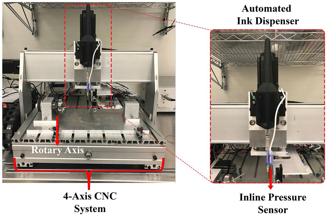
CNC-based 4 axis conductive ink printing system with a rotary axis for nonplanar fabrication. The 3D printed automated conductive ink dispenser with the disposable inline pressure sensor is mounted on the z-axis. Abbreviation: CNC, computer numeric control
2.2 |. MRI-compatible active needle design and characterization
Design specifications of the active needle prototype were determined for clinical use by the interventional cardiologists in our group. The final prototype was expected to have 20G (0.87 mm) OD and 90 mm usable length. The needle inner diameter (ID) requires to be compatible with 0.014” (0.36 mm) OD guidewires. Whole device visibility provided by a single-loop coil58 without distinct markers may result in the misconception of device tip location when the distal portion of the device is off the imaging plane.28,59 Thus, 3 distinct markers with 30 mm spacing were required for accurate estimation of the tip location and penetration depth. Solenoid coil geometry was implemented to concentrate the forward polarization RF-magnetic field () around the markers and provide distinct marker visibility. Individual marker length was limited to between 2 mm and 4 mm to minimize anatomical data obscured by the marker artifact.
2.2.1 |. Electromagnetic simulations
By the reciprocity principle, can be used to predict the receive sensitivity and the near-field SNR of a RF antenna.60 Finite-difference time-domain simulations were performed to calculate the distribution and visualize magnetic (B) field vectors to optimize coil parameters and desired antenna geometry. Sim4Life 6.2 (Zurich MedTech AG, Switzerland) electromagnetic simulation software was used.
Solenoid coil behavior in the presence of a metal conductor such as a metal needle body in the solenoid axis is well examined in the literature.37 Briefly, solenoid pitch is one of the factors affecting a coil’s coupling efficiency with the surrounding B field.61 In the case of a metallic needle having an integrated RF-receiver antenna, the induced common mode currents on the metallic needle body generate a transverse B field, which is perpendicular to the longitudinal axis of the solenoid. The solenoid portions of the antenna can couple to this field if the solenoid pitch is sufficiently loose, which might cause the RF-induced temperature to decrease or increase, depending on the solenoid pitch and length and the distance between solenoids.37 We aimed to minimize this coupling for distinct marker visibility.
A 3D model of the active needle prototype consisting of 3 solenoid coils connected by straight conductors (Figure 2A) was prepared adhering to the actual component dimensions (Figure 2B). 5 μm isotropic voxel size was used to accurately discretize the thin-film RF antenna and polyester tubing. The needle and printed RF antenna materials were defined as resistive conductors with 80 Ω/m and 50 Ω/m impedance at 23.66 MHz, respectively. Active needle models were partially immersed in a gel phantom with electrical conductivity of 0.47 S/m and relative permittivity of 80. The birdcage coil used for RF excitation in clinical MRI scanners was excluded for computational simplicity. The printed RF antenna was excited at the proximal end to exploit the reciprocity principle. Active needle models were simulated first parallel and then perpendicular to B0 to evaluate the orientation dependence of the RF antenna performance. The 10-furn solenoids previously provided sufficient inductance (~35 nH) to produce distinctly visible markers.57 The number of solenoid turns was kept as 10 to limit the number of optimization parameters. First, incremental lengths (2 mm, 2.5 mm, 3 mm, and 4 mm) of a 10-turn solenoid coil were tested. Next, effects of the conductor thickness and normalized pitch (p = the ratio of the distance between the adjacent turns divided by the conductor diameter)37 were assessed. Only 20 μm and 50 μm were tested as the conductor thickness because they represent the target printed conductive ink thickness and insulated copper wire diameter used to build a comparator needle, respectively. Effects of the electrical conductivity were not investigated via simulations. The magnitude alongside the needle was calculated on a straight line 1 mm away and parallel to the needle.
FIGURE 2.
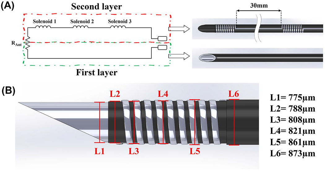
(A) Simplified schematic representation of the active needle RF antenna and corresponding printed polymer layers (parasitic capacitance of the solenoid coils and the transmission line is ignored). (B) 3D drawing of the active needle prototype used for the electromagnetic simulations, showing the individual component dimensions. Polymer layers are retracted on the drawing to expose the normally encapsulated components. (L1 is the OD of the nitinol hypotube; L2 is the OD after the first layer polyester tube only; L3 is the OD after conductive ink printing on the first layer polyester tube; L4 is the OD after the second layer polyester tube only; and L5 is the OD after conductive in printing on the second layer polyester tube. L6 is the final OD of the active needle.). Abbreviations: L, length; OD, outer diameter
2.2.2 |. MRI-compatible active needle design
An MRI-compatible nitinol hypotube (Memry Corp, CT) with 0.610 ± 0.025 mm ID and 0.775 ± 0.025 mm OD was cut to 10 cm length, and the distal tip of the tube was shaped as a sharp needle using a laser cutter (Lasag, Bern, Switzerland). A loop RF antenna was printed on biocompatible heat-shrink polyester tubing with 1.067 mm expanded ID and 6.35 μm wall thickness (103-0154, Nordson Medical, MA) as 2 coaxial layers using silver conductive ink (AG-510, Kayaku Advanced Materials, MA). The skin depth for the silver conductive ink at 23.66 MHz can be calculated as 16.9 μm.62 20 μm conductor thickness was targeted to eliminate the skin effect. The first layer polyester tube contained only a straight line (Figure 3A), whereas the second layer had 3 solenoid coils 30 mm apart but connected with straight lines in series (Figure 3B). According to simulation results, 2 mm long solenoid coils would provide the highest peak-to-peak marker SNR. However, 2.5 mm long, 10-turn solenoid coils were preferred because 32G (240 μm OD) needle tips were used as the ink outlet. 150 μm conductor width (P = .67) was targeted to minimize the transverse magnetic field coupling. The printed coil and conductor dimensions were measured using an optical microscope (SOL, MicroVu, CA). The conductive ink printed polyester heat-shrink tubing was placed onto the nitinol needle body and heat-shrunk at 135°C using a hot air station (210-A, BEAHM Design Inc., CA). The coaxial polyester printed layers were electrically connected at the distal end using the silver conductive ink to complete the antenna circuit. 1 mm long electrical connectors were formed from a nitinol hypotube with 0.864 ± 0.025 mm ID and 0.965 ± 0.025 mm OD (Memry Corp, CT) via laser cutting and soldered to a 36 American Wire Gauge (AWG) micro-coaxial cable (9436-WH033, Alpha Wire, NJ). A silver epoxy (8331S, MG Chemicals, Ontario, Canada) was applied to the inner lumen of the hypotube pieces and connected to the proximal ends of the printed RF antenna. The same polyester tube was applied over the second layer to completely insulate the printed antenna (Figure 3E). A custom Luer-lock hub was 3D-printed and assembled on the active needle prototypes to connect with standard syringes (Figure 3F). The total DC resistance of the printed antenna was measured before and after the heat treatment using a vendor-calibrated multi-meter (117, Fluke, WA).
FIGURE 3.
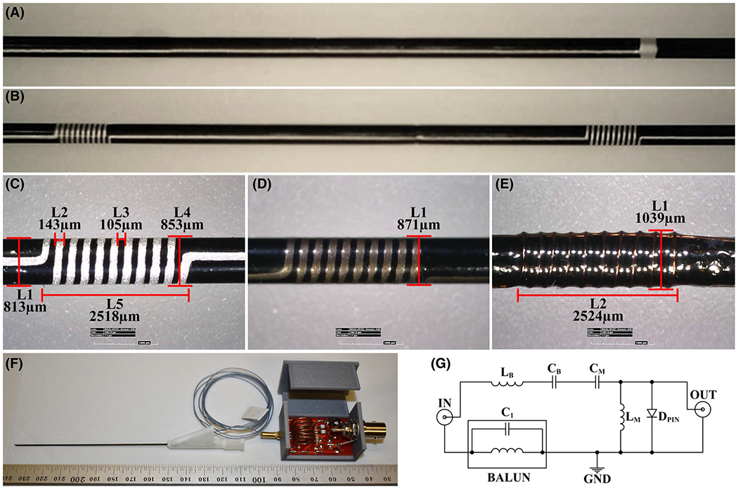
(A) The first layer conductive ink printed polyester tube consisting only a straight line, and (B) the second layer conductive ink printed polyester tube with solenoid coils of the RF antenna connected with straight lines. (C) Optical microscope measurements of the printed solenoid coils (L1 is the needle diameter after the second polyester layer; L2 is the printed conductor width; L3 is the distance between the adjacent windings; L4 is the needle diameter after the second printed layer; and L5 is the solenoid coil length). Final profile measurements of the active needle prototypes (D) with the printed RF antenna and (E) with the insulated copper wire wound RF antenna. L1 is the final needle OD, and L2 is the solenoid coil length. (F) The final assembly of the active needle prototype with the custom Luer-lock hub, micro coaxial cable, and the tune and match circuit. (G) Tune-and-match circuit diagram of the RF antennas. (A)-(D) belong to the active needle prototype with the conductive ink printed antenna. (E) Belongs to the active needle prototype with the 44 AWG insulated copper wire antenna. Abbreviations: AWG, American wire gauge; L, length
For a higher quality comparison, another active needle prototype with a nearly identical design incorporating a manually wound RF antenna was built using a 44 AWG enamel-coated copper wire (79748#039, Remington Industries, IL) and the same nitinol hypotube (0.775 μm OD). Because the enamel coating on the copper wire is very thin, the heat-shrink polyester tube was applied onto the nitinol needle body first, then the copper wire wound antenna was integrated onto the polyester layer to minimize coupling with the metal needle body. The heat-shrink polyester tube was applied onto the copper wire antenna to mimic the printed RF antenna construction (Figure 3E). The proximal ends of the insulated copper wire RF-receiver antenna were soldered directly to the 36 AWG micro-coax cable.
The active needle prototypes were tuned to 23.66 MHz and matched to 50 Ω remotely at the proximal end of the micro-coax cable using a vector network analyzer (4395a, Agilent, CA). A balanced-to-unbalanced connection was used to eliminate the shield common mode currents. A serial capacitor and a parallel inductor were used for impedance matching. A PIN diode was used to minimize coupling between the needle RF antenna and the scanner RF-transmit coils during RF excitation to minimize RF-induced heating (Figure 3G). The micro-coax cable was shortened until a 90° phase difference (λ/4), at 23.66 MHz, between the PIN diode and the RF antenna was obtained so that the low impedance, when the PIN diode is activated, can be translated as a high impedance at the RF antenna end.
2.2.3 |. In vitro characterization
The mechanical performance of the active needle prototype was evaluated via bending and puncture tests per American Society for Testing and Materials standard (ASTM) F187463 and ASTM F2132,64 respectively. Results were compared to commercially available 20G puncture needles, including a non-MRI–compatible stainless-steel (BD Spinal Needle, Becton, Dickinson and Company, NJ), and MRI conditional titanium (Philips Invivo, Germany) and Inconel needles (MReye Chiba, Cook Medical, IN). Detailed description of the test methods is presented in Supporting Information Material, section 2 (Figure S3).
A real-time balanced steady-state free precession (bSSFP) pulse sequence (TE/TR: 1.05/2.50 ms, flip angle: 45°/60°/75°, FOV: 320 × 320 mm, bandwidth: 1042 Hz/Px, matrix: 192 × 144, slice thickness: 6 mm, 3 fps), typically used for clinical MRI catheterization at 0.55T at our institution, was used during the in vitro tests. The bSSFP sequence is prevalent in iMRI due to favorable image contrast and image acquisition speed. Due to the high specific absorption rate (SAR) brought about by the short TR/high flip angle combination, bSSFP presents an appropriate upper limit in SAR for the active iMRI devices.11,65 In vitro RF-induced heating and imaging performance of the active needle prototypes were tested using a high-performance low-field scanner at 0.55T (prototype Magnetom Aera, Siemens Healthcare, Erlangen, Germany).
The RF-induced heating performance of the active needle prototypes was tested in a gel phantom per ASTM 2182-19.66 The active needle prototypes were immersed in the middle of the gel phantom, 45° oblique to z-axis, parallel to B0, and 2 cm away from the right edge of the phantom where the SAR is maximum (determined via previous experiments)43 and the heat dissipation is minimum. Scans were performed in the “first level” SAR mode (max. 4 W/kg), and the reported whole body SAR value was 2.78 W/kg, 3.56 W/kg, and 3.96 W/kg for 45°, 65°, and 75° flip angle, respectively. Temperature measurements were performed using fiber optic temperature sensors (OPT M-170, OpSens, Canada). Temperature probes were attached to the needle body using polyamide hypotubes with 80 μm ID and 90 μm OD (214-1584, Nordson Medical, MA), and 3 mm long heat-shrink polymers, as described before.67 First, the location of the “hot spot” was confirmed by gradually withdrawing the temperature probe lengthwise, “profiling” the temperature rise alongside the needle prototypes. Next, heating measurements were performed at the hot spot. The baseline temperature was recorded for 30 s before each scan, and then needle prototypes were scanned for 90 s, which represents the starting point of the plateau after the clinically significant temperature rise. The coupling efficiency of 2 loop coils increases with the decreasing distance between coils and maximizes when they are parallel.68 The test was repeated by placing the active needle prototypes in the same location but perpendicular to the B0 to increase the coupling between needle solenoid coils and the RF transmit system of the scanner. Increased coupling was confirmed via heating measurements. Additional in vitro 2-port vector network analyzer measurements or induced current measurements were not performed. Temperature profiling was repeated for each needle and orientation. Finally, the active needle prototypes were scanned with 75° flip angle for 15 min, perpendicular to the B0, to simulate a challenging, uninterrupted, long MRI scan.
The in vitro MRI visibility performance of the active needle prototypes was tested using the same real-time bSSFP sequence but with only 45° flip angle in the ASTM gel phantom. First, the prototypes were scanned at isocenter, 45° oblique to z-axis and parallel to the B0. Then, the prototypes were rotated perpendicular to the B0 in the same location and scans were repeated. Still MR images were reconstructed using only the active channel signal received from the active needle prototypes, and all other imaging coils were deactivated. The SNR maps of the in vitro MR images were calculated using the pixel SNR method,69 with N = 100 using MatLab (2020a, MathWorks, MA). The SNR profiles on a straight line alongside the active needle prototypes were calculated to assess the MRI marker distinguishability. Real-time in vitro MRI tracking performance of the active needle prototypes was tested during insertion, rotation, and an exaggerated deflection in the FOV. A prototype interactive real-time MRI interface (MonteCarlo, Siemens, Germany) was used with a real-time bSSFP sequence (TE/TR: 2.0/4.0 ms, flip angle: 45°, FOV: 320 × 320 mm, bandwidth: 1042 Hz/Px, matrix: 192 × 144, slice thickness: 8 mm, 3 fps). A 4-element spine coil was used for phantom imaging. The active channel signal was colorized on the MR image14 after scaling with window level/window width = 16/16. Both prototypes were scanned with the same RF receiver gain for the active channel signal. A custom, 3D printed sliding and rotating needle holder was used during tests (Supporting Information Figure S4).
2.2.4 |. In vivo characterization
The real-time in vivo MRI visibility performance of the active needle prototypes was tested in 1 swine under general anesthesia by advancing the active needle prototypes into the liver. Animal experiments were approved by the National Heart, Lung and Blood Institute (NHLBI) Animal Use and Care Committee and performed according to the contemporary National Institutes of Health standards. Nonsterile prototypes were tested as an “add-on” experiment to another nonsurvival porcine experiment to minimize use of animals. All used general anesthesia and mechanical ventilation.
MonteCarlo interactive real-time MRI interface software was used with the same real-time bSSFP sequence used for real-time in vitro MRI. Imaging parameters were tailored for a low frame rate because the liver is a stationary organ. Only a 4-element spine coil underneath the animal was used for the anatomical imaging. No surface coil was used because the tests were performed as an add-on to an open-chest cardiac experiment. The active channel signal was colorized on the MR image14 after scaling with window level/window width = 16/16. Both prototypes were scanned with the same RF receiver gain for the active channel signal. Real-time device tracking was performed manually by adjusting imaging planes. The active marker signal drops off rapidly away from the device antenna, causing a nebulous artifact. The active needle artifact size was measured on DICOM images after isolating the active marker signal and thresholding with cutoff pixel intensity value 5 using MatLab (2020a, MathWorks, MA) to calculate the size of the surrounding anatomy obscured by the marker artifact.
3 |. RESULTS
3.1 |. Conductive ink printing system characterization
The optical microscope measurements of the printed RF antenna components demonstrating the mechanical accuracy of the electromechanical system and the control accuracy of the ink dispenser unit are shown in Figure 3C. The overall system precision provided a fine printing resolution (< 4 μm) (Figure S2B).
3.2 |. Electromagnetic simulations
Figures 4 and 5 show the electromagnetic simulation results of the active needle designs with 2 mm, 2.5 mm, 3 mm, and 4 mm long, 10-turn solenoid coils placed 30 mm apart as MRI markers. distributions show that the antenna sensitivity can be concentrated around the solenoid coils (Figure 4A). Figure 4B shows magnitude profiles alongside the active needle designs. RF antenna sensitivity changes with the conductor thickness, solenoid length and pitch, and needle orientation with respect to B0. Figure 5 shows B field vectors along and among the coil windings. Non-zero transverse B field (rotated field vectors from the longitudinal axis around the windings) presents when the coil pitch is sufficiently loose. Transverse B field approaches 0 if the coil pitch is sufficiently small because of the cancellation between the coil windings. According to simulation results, 2.5 mm long solenoid coils with P = .67 provide sufficiently distinguishable marker visibility and minimize the coupling with transverse B field.
FIGURE 4.
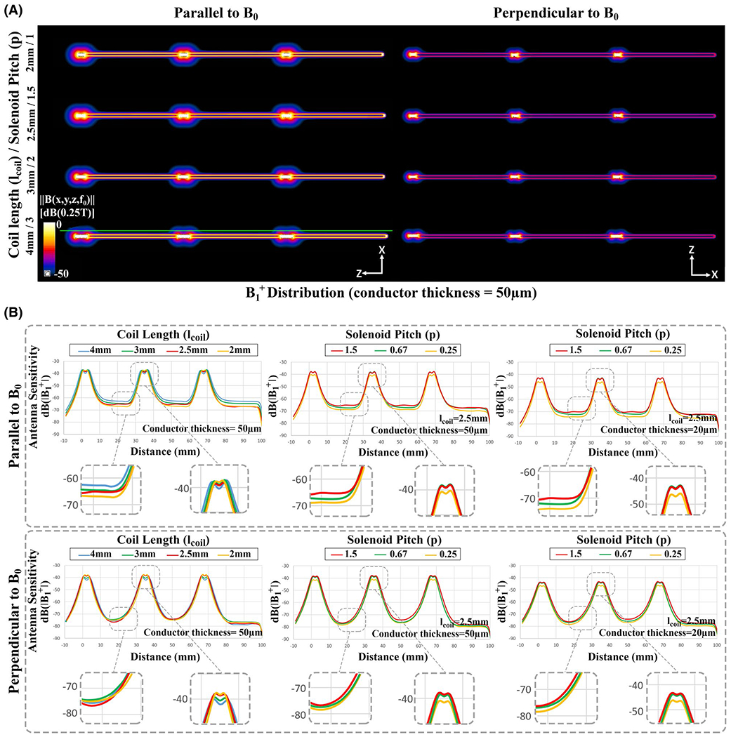
Electromagnetic simulation results of the active needle design. (A) B1+ distribution of the desired antenna geometry with 10-turn solenoid coils. (B) The B1+ magnitude alongside the active needle design showing the effects of the solenoid coil length, conductor thickness, normalized pitch (ratio of the distance between the adjacent turns divided by the conductor diameter), and needle orientation with respect to B0. B1+ profiles were extracted on the green line parallel to active needle models
FIGURE 5.
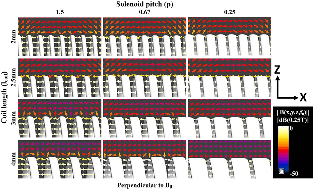
Magnetic field (B) vectors around the windings of 2 mm, 2.5 mm, 3 mm, and 4 mm long, 10-turn solenoid coils with 1.5, 0.67, and 0.25 normalized pitch as the needle is oriented perpendicular to B0. Rotated vectors from the longitudinal axis around the windings indicate the presence of BTr, which is perpendicular to solenoid axis. 2.5 mm long solenoid coil with 0.67 normalized pitch shows sufficient marker visibility and minimizes the BTr coupling. Abbreviation: BTr , transverse magnetic field
3.3 |. MRI-compatible active needle characterization
The optical microscope measurements of the active needle prototypes with the printed and insulated copper wire RF antennas are shown in Figure 3C–E. Total printing time was 86 s. The conductor width and the conductor thickness of the printed RF antennas were measured as 145 ± 3.2 μm and 20 ± 1 μm, respectively (Figure 3C). The final needle diameter was measured as 871 ± 1 μm (Figure 3D) and 1039 ± 1 μm (Figure 3E) for the active needle prototypes with the printed antenna and with the insulated copper wire antenna, respectively. The total DC resistance of the conductive ink printed RF antennas was 221.38 ± 2.57 Ω before and 63.21 ± 2.54 Ω after the heat treatment compared to 0.7 Ω of the insulated copper wire antenna. The heat treatment increased conductivity of the conductive ink 3.5-fold. Mechanical test results of the active needle prototype and commercial equivalents are presented in Supplemental Material, section 2 (Figure S5).
In vitro MR images of the active needle prototypes in the ASTM gel phantom with respect to B0 can be seen in Figure 6 (all images are windowed with the same window width [20]; window level was not changed). The hyper-intense MRI signal picked up by the solenoid coils appears as bright spots on the images serving as MRI markers. Active needle prototypes with insulated copper wire RF antenna and with the printed RF antenna both provided distinct visibility at the marker locations. Figure 7 shows the in vitro SNR maps of the active needle prototypes on the sagittal and axial planes. Each major peak on the intensity profile, plotted alongside the active needle prototypes, represents a solenoid coil (MRI marker) location. Real-time in vitro MRI performance of active needle prototypes during insertion, rotation with respect to B0, and an exaggerated deflection are demonstrated within the Supporting Information (Supporting Information Videos S1 and S2).
FIGURE 6.
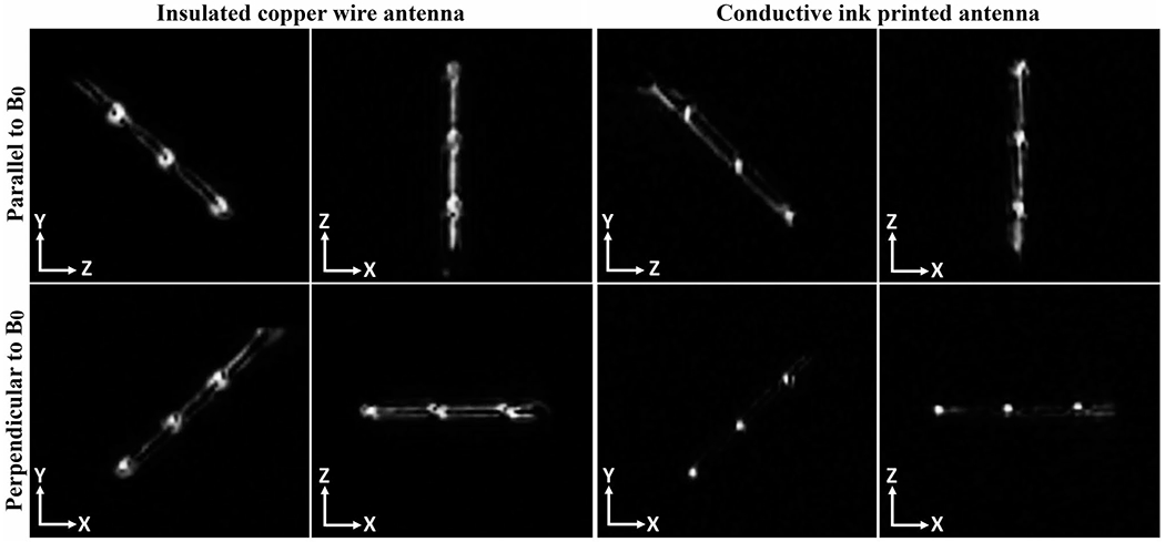
In vitro MR images of the active needle prototypes at 0.55T using a real-time bSSFP imaging sequence. Straight conductors, connecting solenoid coils in series, couple better with the transverse magnetic field when the needle is parallel to B0, providing a bright signal between the solenoid markers. This coupling decreases when the needle is perpendicular to B0, providing a more distinct marker signal. Abbreviations: bSSFP, balanced steady-state free precession; T, tesla
FIGURE 7.
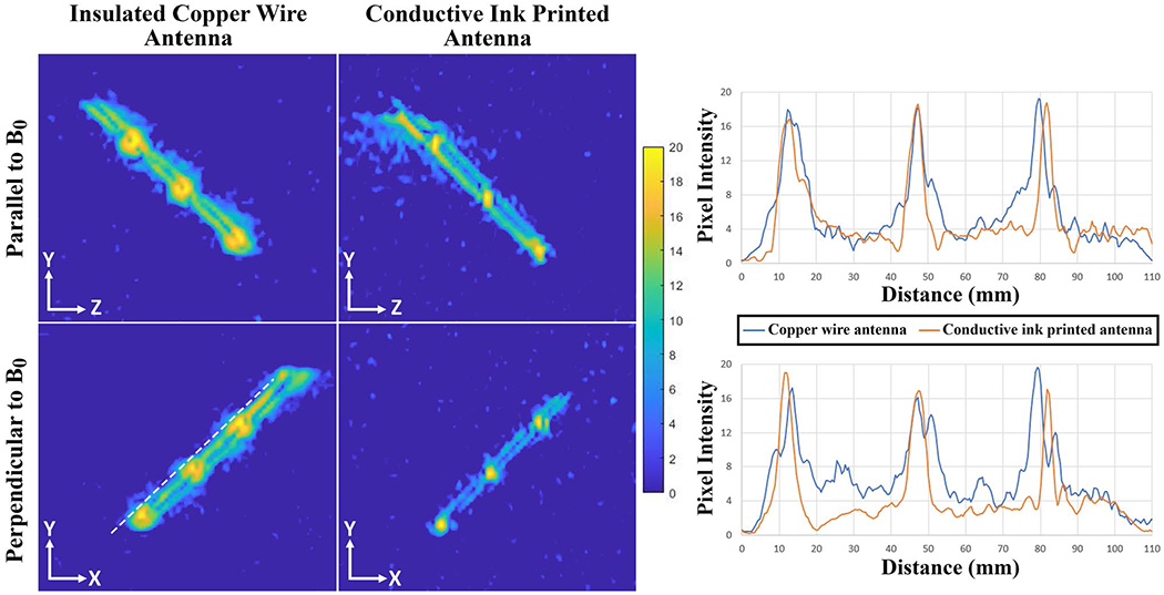
In vitro SNR maps of the active needle prototypes on sagittal and axial planes. Pixel intensity so that the SNR profiles are calculated on a straight line 1 mm away from and parallel to the active needle prototypes (the white dashed line). Major peaks at the pixel intensity profiles represent the solenoid coil locations
RF-induced heating measurements of active needle prototypes in the gel phantom are shown in Figure 8. The hottest spot was at the solenoid coil placed at the distal end of the active needle prototype for both designs. The temperature at the hot spot starts to rise right after the start of the MRI scan and saturates quickly after the first 60 s. The RF-induced heating rise increased with the flip angle. The temperature rise of the conductive ink printed antenna remained under 1°C when it is parallel to B0 and under 1.5°C when it is perpendicular to B0. The temperature rise at the end of the 15 min scan was 1.64°C for a 75° flip angle when the needle is perpendicular to B0. The temperature rise of the insulated copper wire antenna was measured as 3.61°C, 5.05°C, and 6.79°C with 45°, 60°, and 75° flip angles, respectively, when it is parallel to B0. The temperature rise of the same prototype was 4.59°C, 6.08°C; and 7.67°C with 45°, 60°, and 75° flip angles, respectively, when it is perpendicular to B0. The temperature rise at the end of the 15 min scan was 8.21°C for a 75° flip angle when the comparator prototype with copper wire antenna is perpendicular to B0. The temperature rise of the bare nitinol needle body at the needle tip (hot spot) was recorded as 0.54°C with 60° flip angle, at the end of 90 s when it is parallel to B0.
FIGURE 8.

RF-induced heating measurements of the active needle prototypes parallel and perpendicular to B0 for 90 s and 15 min, and the RF-induced heating measurement of a bare nitinol needle body parallel to B0 for 90 s. The dash line indicates the start of the MRI scan and the solid line indicates the stop of the MRI scan. The RF-induced heating rise of the active needle prototype with the insulated copper wire antenna exceeds clinically acceptable limits (> 2°C) in every condition. Abbreviation: FA, flip angle
The real-time MRI signal received from the active needle prototypes via a separate channel was colorized and scaled with window level/window width = 16/16, then superimposed on the monochromatic MR images at 3 fps during the in vivo liver intervention. The real-time in vivo MR images of the active needle prototypes are shown on sagittal and axial planes (Figure 9). Intersecting slices in the real-time acquisition create cross-plane signal saturation and produce dark lines in the images. The MRI marker artifact diameter generated by the active needle prototype with the insulated copper wire antenna measured 6.98 ± 0.49 mm on the axial plane and 5.75 ± 1.44 mm on the sagittal plane, compared to 4.59 ± 0.28 mm and 4.73 ± 0.05 mm on the corresponding planes for the active needle prototype with the printed antenna (Figure 9). Real-time MRI videos of needle interventions are provided within the Supporting Information (Supporting Information Videos S3 and S4).
FIGURE 9.
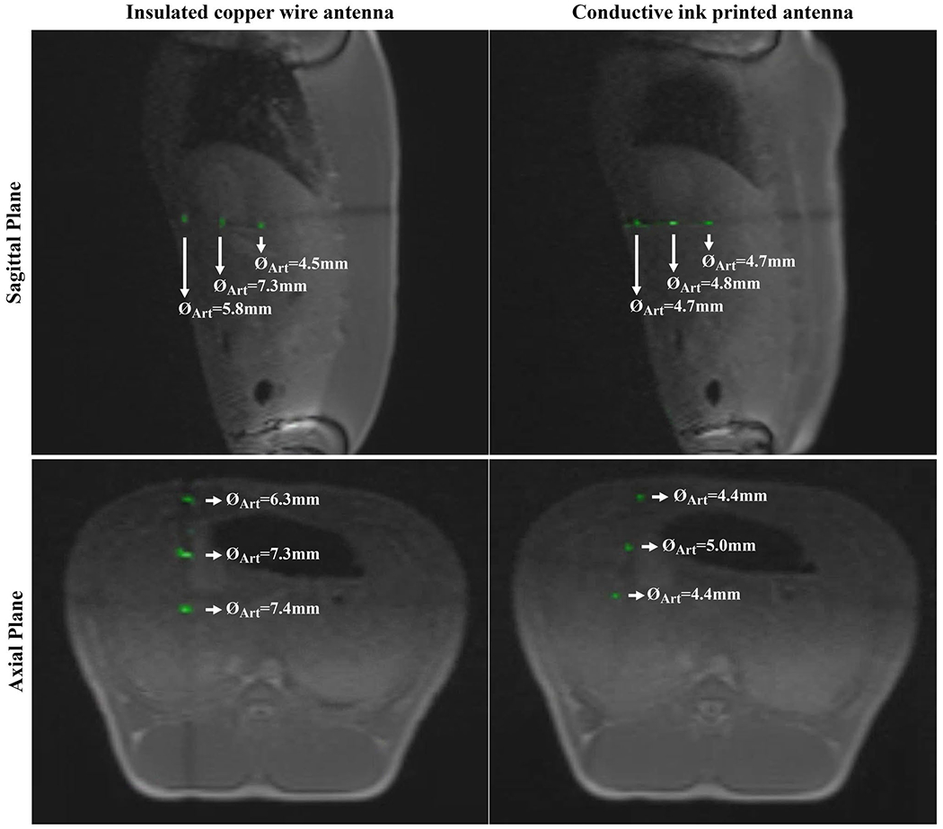
In vivo real-time MRI of the active needle prototypes. The active needle signal is colorized after windowing with window width/window level = 16/16. The printed RF-antenna provides a more refined marker signal, obscuring less anatomical information compared to the insulated copper wire RF-antenna
4 |. DISCUSSION
This study presents a novel method for fabricating active iMRI devices using conductive ink and introduces a 90 mm long, 20G active needle design with 0.610 ± 0.025 mm ID compatible with guidewires up to 0.023” (0.584 mm) OD for iMRI procedures at 0.55T.
The mechanical accuracy of the computer numeric control–based electromechanical system showed the fine printing capabilities of the proposed method with ~4 μm resolution (Figure S2B). This technique eliminates the timeconsuming and/or expensive preparations required for alternative microelectromechanical systems-based fabrication methods.25,39,45,47,49,70 Moreover, any change in the desired RF antenna geometry can be applied instantaneously by modifying the corresponding part of the software control code without the need for any alterations in the fabrication setup.
A lump-free overall device profile is crucial for an interventional device design because surface irregularities compromise the functionality and safety (tissue injury). The printed antenna had only a modest impact on the 0.775 mm hypotube diameter compared with the insulated copper wire antenna (95 μm vs. 264 μm) (Figure 3D,3E). Likewise, the maximum profile alteration along the active needle prototype surface with the printed antenna (20 μm) was lower than the prototype with the 44 AWG insulated copper wire antenna (113 μm).
Mechanical test results showed that the active needle prototype is ~32% to 40% more flexible than commercially available equivalents (Supporting Information Figure S5A). This is attributed to super-elastic material properties of nitinol71 and thin wall thickness (82.5 μm) of the nitinol hypotube used in this study compared to commercial equivalents (~175 μm). Moreover, the active needle prototype performed as well or even better than commercial equivalents during puncture tests (Supporting Information Figure S5B). Additionally, the active needle prototype successfully punctured the skin tissue, a relatively hard tissue compared to target internal organs, and reached to the liver without a significant deflection during in vivo experiments. We hypothesize that stiffer nitinol hypotubes,57 other MRI conditional alloys (eg, titanium, Inconel, 316LVM stainless steel), or even commercially available MRI conditional needles can be used to fabricate stiffer active needles using the proposed method.
The needle RF antenna geometry was optimized using the electromagnetic simulation results. Simulation results showed that the RF antenna sensitivity can be concentrated around solenoid coils as distinct markers (Figure 4). Straight conductors of a RF receive antenna couple only with the magnetic field perpendicular to the conductor axis generated by proton spins, and this coupling maximizes when the conductors are parallel to B0 and diminishes when the conductors are perpendicular to B0 during MRI.29 As a result, sensitivity of straight conductors between solenoid coils drops when the antenna is perpendicular to B0. Shorter solenoids demonstrated less sensitivity drop along the coil, approximating a single peak. Maximum peak-to-peak marker SNR can be achieved using 2 mm long solenoid coils with an insignificant difference (~2 dB) from 2.5 mm long solenoids (Figure 4B). Non-zero transverse magnetic field can be observed in the close vicinity of the solenoid turns if the solenoid pitch is sufficiently loose (Figure 5). B field vectors were analyzed only for the case in which needle prototypes are oriented perpendicular to B0 because it is the most common use of interventional needles. Similar and adequate RF antenna performance at various angles with respect to B0 was shown via in vitro MRI. 2.5 mm long, 10-turn solenoids were chosen because a 32G (240 μm OD) needle tip was used as the ink outlet and they would provide sufficient visibility, minimizing transverse B field coupling based on the simulation results. A smaller diameter needle tip can be used to print shorter and tighter pitch coils for more distinct markers. However, the skin effect62 and the relationship between the near-field SNR and conductor thickness29 need to be considered. Alternatively, a single loop (saddle) coil can be employed for whole shaft visibility; or longer, loose-pitch solenoids can be used for less distinguished and longer markers.58
The RF-induced heating rise of the active needle prototype with the insulated copper wire antenna far exceeded clinically acceptable heating limits (>> 2°C) in almost all cases, even at low field (low SAR). The RF-induced heating rise of the active needle prototype with the printed antenna always remained under the clinically significant limits (< 1.65°C) even for an extended imaging duration well beyond typical use (Figure 8). The RF-induced heating of metallic parts under MRI is dominated by resistive coupling due to resistive mismatch between the conductor and surrounding tissue.33 A lower resistance conductor such as insulated copper wire increases the resistive mismatch causing a higher RF-induced heating. The printed antenna exhibited a distributed resistance due to the high intrinsic resistivity of the conductive ink, resulting a lower RF-induced heating. We predict that, based on these observations, the RF-i nduced heating risk of an interventional MRI device antenna can be minimized using printed conductors even with the use of higher field (1.5 or 3.0T) clinical scanners. The tuning and matching of the antenna need to be adjusted for higher field Larmor frequencies.57
In vitro and in vivo MRI visibility performance of the conductive ink printed antenna was comparable to the insulated copper wire antenna, demonstrating the real-time device tracking capability (Figures 6, 7, and 9). Both prototypes provided sufficient in vitro real-time MRI visibility during insertion, rotation with respect to B0, and an exaggerated deflection in the FOV (Supporting Information Videos S1 and S2). Conductive ink printed markers exhibited a smaller size artifact (~4.65 mm) compared to the insulated copper wire markers (~6.4 mm). The wire thickness of the insulated copper wire (44 AWG, 50 μm) is 2.5 times bigger than the conductive ink printed conductor (20 μm). The difference between the artifact sizes is attributed to the relationship between the wire diameter and the near-field SNR29 explained by the Biot-Savart law. Also, the coil quality of the insulated copper wire antenna is inherently higher than the conductive ink printed antenna because of the increased coil loss72 due to the high intrinsic resistivity of the conductive ink. Although the total impedance (RAntenna + RCable) matching helps to reduce signal losses, the impedance mismatch between the high-resistance printed antenna and low-resistance coaxial cable causes transmission losses between the printed antenna and the coaxial cable. The impedance matching can be performed at the proximal end of the printed antenna before the micro coaxial cable connection to minimize the resistive mismatch losses.
In vivo signal signature of the active needle prototypes was very well matched to the in vitro signature and electromagnetic simulation results. Real-time in vivo needle visualization was performed by manually adjusting the imaging planes. No projection-based tracking was applied.27 Temporary individual marker signal loss on individual imaging planes was observed due to respiratory motion or slight needle deflection (Supporting Information Videos S3 and S4). However, tracking of individual marker signals and needle position was feasible on other imaging planes. Alternatively, imaging planes can be adjusted to capture any specific marker signal. The imaging speed was set at 3 fps, which is sufficient for this application because the liver is only affected by respiratory motion. The active needle prototypes were well visualized even when using relatively thick 8 mm slices (Figure 9). The in vivo visualization performance was found acceptable and comparable to previously reviewed iMRI devices12,17,27 by the interventional cardiologists and MRI technologists in our group when using a validated acquisition strategy. Hence, we believe that clinical translation of the needle prototype is feasible.
Real-rime imaging speed and anatomical image quality can be tuned with particular applications in mind, for example, by using alternative reconstruction and parallel imaging methods,12,15,16 although in this work we calibrated device visibility for use in conjunction with our established clinical acquisition method. We predict that at higher imaging frame rates, obtained by increased undersampling, or at higher image spatial resolution, the marker SNR would diminish as predicted by the standard SNR relationships in MRI. However, because the signal from coils on the needle prototype can be processed independently for display, marker visibility can be preserved as long as the marker signal is higher than background noise. In vitro, the markers displayed a peak-to-trough contrast-to-noise ratio of ~16-20 (Figure 7), indicating that even with significant increases in undersampling or spatial resolution, marker visualization should be feasible (ie, contrast-to-noise ratio > 5). Further work is required to determine the limits of device visibility.
5 |. CONCLUSION
In this work, a custom, computer numeric control–based conductive ink printing method was introduced for nonplanar iMRI device fabrication. The medical grade device manufacturing capability of the proposed method was successfully demonstrated by prototyping a low profile 20G (0.87 mm OD) active iMRI needle. The active needle prototype was clearly visible both in vitro and in vivo during real-time MRI at a 0.55T prototype scanner. The RF-induced heating test results showed that the active needle fabricated using conductive ink heated less than the nearly identical active needle fabricated using insulated copper wire antenna. The maximum temperature rise (1.64°C) was clinically acceptable. This technology will enable fabrication of lower-profile interventional MRI devices, especially attractive for pediatric or other less-invasive procedures.
Supplementary Material
FIGURE S1 Closed-loop Proportional-Integral-Derivative (PID) control diagram of the ink dispenser unit where R(t) is the target pressure value (reference), e(t) is the calculated error between the reference value and the actual pressure, Kp is the proportional coefficient, Ki is the integral coefficient, Kd is the derivative coefficient, L(t) is the linear position of the actuator, M(t) is the linear to angular position conversion, S(t) is the step calculation and the p(t) is the actual pressure value from the sensor and q(t) is the calculated material flow
FIGURE S2 (A) PID controller response to the reference inputs including a step profile, a fast changing profile and a programmable profile with the corresponding controller error margins showing the ink dispenser unit control accuracy test. (B) Circumferential straight lines printed on a 5Fr Pebax hypotube with 1mm, 3mm, 5mm and 10mm separations for the mechanical accuracy test of the electromechanical system
FIGURE S3 Mechanical test setup for (A) the bending and (B) puncture tests. Same setup was used for both tests with small modifications
FIGURE S4 Test results of (A) the bending and (B) puncture tests. Each test was repeated three times per needle and the average of the results are plotted. The red dashed line on the graphs indicate the beginning of the retraction phase for each test
FIGURE S5 Custom, 3D printed sliding and rotating needle holder (A) 45° rotated and (B) vertically fixed. Active needle prototype is mounted on the needle holder and slid and/or rotated in the field of view
VIDEO S3 In -vivo real-time MRI of the active needle prototype with conductive ink printed antenna during a liver intervention
VIDEO S4 In -vivo real-time MRI of the active needle prototype with 44 AWG insulated copper wire antenna during a liver intervention
VIDEO S2 In -vitro real-time MRI of the active needle prototype with 44 AWG insulated copper wire antenna during a liver intervention
VIDEO S1 In -vitro real-time MRI of the active needle prototype with conductive ink printed antenna during a liver intervention
ACKNOWLEDGMENT
The authors thank Katherine Lucas, Victoria Haley, and William Schenke for their invaluable supports during the in vivo animal experiments. Research reported in this publication was supported by National Heart Lung and Blood Institute, Division of Intramural Research award Z01-HL006041 “MRI and X-ray catheter design and prototyping” (to r.j.l.). The content is solely the responsibility of the authors and does not necessarily represent the official views of the National Institutes of Health. The authors acknowledge the assistance of Siemens Healthineers in the modification of the MRI system for operation at 0.55T and for providing the MonteCarlo prototype under an existing cooperative research and development agreement between National Heart, Lung and Blood Institute and Siemens Healthineers.
Funding information
Supported by the National Heart, Lung and Blood Institute (NHLBI) Division of Intramural Research (DIR) award Z01-HL006041 “MRI and X-ray catheter design and prototyping” (to r.j.l.)
Footnotes
SUPPORTING INFORMATION
Additional Supporting Information may be found online in the Supporting Information section.
REFERENCES
- 1.Nour SG, Lewin JS. Percutaneous biopsy from blinded to MR guided: an update on current techniques and applications. Magn Reson Imaging Clin N Am. 2005;13:441–464. [DOI] [PubMed] [Google Scholar]
- 2.Diracoglu D, Alptekin K, Dikici F, Balci HI, Ozcakar L, Aksoy C. Evaluation of needle positioning during blind intra-articular hip injections for osteoarthritis: fluoroscopy versus arthrography. Arch Phys Med Rehabil. 2009;90:2112–2115. [DOI] [PubMed] [Google Scholar]
- 3.Amedee RG, Dhurandhar NR. Fine-needle aspiration biopsy. Laryngoscope. 2001. ;111:1551–1557. [DOI] [PubMed] [Google Scholar]
- 4.Stein HL, Evans JA. Percutaneous transthoracic lung biopsy utilizing image amplification. Radiology. 1966;87:350. [DOI] [PubMed] [Google Scholar]
- 5.Lal H, Neyaz Z, Nath A, Borah S. CT-guided percutaneous biopsy of intrathoracic lesions. Korean J Radiol. 2012;13:210–226. [DOI] [PMC free article] [PubMed] [Google Scholar]
- 6.Kim JW, Shin SS. Ultrasound-guided percutaneous core needle biopsy of abdominal viscera: tips to ensure safe and effective biopsy. Korean J Radiol. 2017;18:309–322. [DOI] [PMC free article] [PubMed] [Google Scholar]
- 7.Bergero MA, Martinez PF, Radtke JP, Hadaschik BA. Multiparametric-MRI-guided biopsy in the era of precision medicine. Arch Esp Urol. 2017;70:833–844. [PubMed] [Google Scholar]
- 8.Meeuwis C, Peters N, Mali WP, et al. Targeting difficult accessible breast lesions: MRI-guided needle localization using a freehand technique in a 3.0 T closed bore magnet. Eur J Radiol. 2007;62:283–288. [DOI] [PubMed] [Google Scholar]
- 9.DeAngelis GA, Moran RE, Fajardo LL, Mugler JP, Christopher JM, Harvey JA. MRI-guided needle localization: technique. Semin Ultrasound CT MR. 2000;21:337–350. [DOI] [PubMed] [Google Scholar]
- 10.Weiss CR, Nour SG, Lewin JS. MR-guided biopsy: a review of current techniques and applications. J Magn Reson Imaging. 2008;27:311–325. [DOI] [PubMed] [Google Scholar]
- 11.Rogers T, Lederman RJ. Interventional CMR: clinical applications and future directions. Curr Cardiol Rep. 2015;17:31. [DOI] [PMC free article] [PubMed] [Google Scholar]
- 12.Nageotte SJ, Lederman RJ, Ratnayaka K. MRI catheterization: ready for broad adoption. Pediatr Cardiol. 2020;41:503–513. [DOI] [PMC free article] [PubMed] [Google Scholar]
- 13.Ratnayaka K, Faranesh AZ, Guttman MA, Kocaturk O, Saikus CE, Lederman RJ. Interventional cardiovascular magnetic resonance: still tantalizing. J Cardiovasc Magn Reson. 2008;10:62. [DOI] [PMC free article] [PubMed] [Google Scholar]
- 14.Guttman MA, Ozturk C, Raval AN, et al. Interventional cardiovascular procedures guided by real-time MR imaging: an interactive interface using multiple slices, adaptive projection modes and live 3D renderings. J Magn Reson Imaging. 2007;26:1429–1435. [DOI] [PMC free article] [PubMed] [Google Scholar]
- 15.Guttman MA, Lederman RJ, Sorger JM, McVeigh ER. Real-time volume rendered MRI for interventional guidance. J Cardiovasc Magn Reson. 2002;4:431–442. [DOI] [PMC free article] [PubMed] [Google Scholar]
- 16.Campbell-Washburn AE, Tavallaei MA, Pop M, et al. Real-time MRI guidance of cardiac interventions. J Magn Reson Imaging. 2017;46:935–950. [DOI] [PMC free article] [PubMed] [Google Scholar]
- 17.Settecase F, Martin AJ, Lillaney P, Losey A, Hetts SW. Magnetic resonance-guided passive catheter tracking for endovascular therapy. Magn Reson Imaging Clin N Am. 2015;23:591–605. [DOI] [PMC free article] [PubMed] [Google Scholar]
- 18.Miquel ME, Hegde S, Muthurangu V, et al. Visualization and tracking of an inflatable balloon catheter using SSFP in a flow phantom and in the heart and great vessels of patients. Magn Reson Med. 2004;51:988–995. [DOI] [PubMed] [Google Scholar]
- 19.Frahm C, Gehl HB, Melchert UH, Weiss HD. Visualization of magnetic resonance-compatible needles at 1.5 and 0.2 Tesla. Cardiovasc Intervent Radiol. 1996;19:335–340. [DOI] [PubMed] [Google Scholar]
- 20.Basar B, Sonmez M, Yildirim DK, et al. Susceptibility artifacts of metallic markers and cardiac catheterization devices on a high-performance 0.55T MRI system. Magn Reson Imaging. 2021;77:14–20. [DOI] [PMC free article] [PubMed] [Google Scholar]
- 21.Omary RA, Unal O, Koscielski DS, et al. Real-time MR imaging-guided passive catheter tracking with use of gadolinium-tilled catheters. J Vasc Interv Radiol. 2000;11:1079–1085. [DOI] [PubMed] [Google Scholar]
- 22.Penzkofer T, Peykan N, Schmidt K, Krombach G, Kuhl CK. How MRI compatible is “MRI compatible”? A systematic comparison of artifacts caused by biopsy needles at 3.0 and 1.5 T. Cardiovasc Intervent Radiol. 2013;36:1646–1657. [DOI] [PubMed] [Google Scholar]
- 23.Kühn J-P, Langner S, Hegenscheid K, et al. Magnetic resonance-guided upper abdominal biopsies in a high-field wide-bore 3-T MRI system: feasibility, handling, and needle artefacts. Eur Radiol. 2010;20:2414–2421. [DOI] [PubMed] [Google Scholar]
- 24.Stadler A, Schima W, Ba-Ssalamah A, Kettenbach J, Eisenhuber E. Artifacts in body MR imaging: their appearance and how to eliminate them. Eur Radiol. 2007;17:1242–1255. [DOI] [PubMed] [Google Scholar]
- 25.Baysoy E, Yildirim DK, Ozsoy C, Mutlu S, Kocaturk O. Thin film based semi-active resonant marker design for low profile interventional cardiovascular MRI devices. MAGMA. 2017;30:93–101. [DOI] [PubMed] [Google Scholar]
- 26.Quick HH, Zenge MO, Kuehl H, et al. Interventional magnetic resonance angiography with no strings attached: wireless active catheter visualization. Magn Reson Med. 2005;53:446–455. [DOI] [PubMed] [Google Scholar]
- 27.Wang W Magnetic resonance-guided active catheter tracking. Magn Reson Imaging Clin N Am. 2015;23:579–589. [DOI] [PMC free article] [PubMed] [Google Scholar]
- 28.Saikus CE, Ratnayaka K, Barbash IM, et al. MRI-guided vascular access with an active visualization needle. J Magn Reson Imaging. 2011;34:1159–1166. [DOI] [PMC free article] [PubMed] [Google Scholar]
- 29.Ocali O, Atalar E. Intravascular magnetic resonance imaging using a loopless catheter antenna. Magn Reson Med. 1997;37:112–118. [DOI] [PubMed] [Google Scholar]
- 30.Ladd ME, Debatin JF. Interventional and intravascular MR angiography. Herz. 2000;25:440–451. [DOI] [PubMed] [Google Scholar]
- 31.Bock M, Müller S, Zuehlsdorff S, et al. Active catheter tracking using parallel MRI and real-time image reconstruction. Magn Reson Med. 2006;55:1454–1459. [DOI] [PubMed] [Google Scholar]
- 32.Dumoulin CL, Souza SP, Darrow RD. Real-time position monitoring of invasive devices using magnetic resonance. Magn Reson Med. 1993;29:411–415. [DOI] [PubMed] [Google Scholar]
- 33.Yeung CJ, Susil RC, Atalar E. RF safety of wires in interventional MRI: using a safety index. Magn Reson Med. 2002;47:187–193. [DOI] [PubMed] [Google Scholar]
- 34.Yeung CJ, Atalar E. RF transmit power limit for the barewire loopless catheter antenna. J Magn Reson Imaging. 2000;12:86–91. [DOI] [PubMed] [Google Scholar]
- 35.Weiss S, Wirtz D, David B, et al. In vivo evaluation and proof of radiofrequency safety of a novel diagnostic MR-electrophysiology catheter. Magn Reson Med. 2011;65:770–777. [DOI] [PMC free article] [PubMed] [Google Scholar]
- 36.Yaras YS, Yildirim DK, Kocaturk O, Degertekin FL. Sensitivity and phase response of FBG based acousto-optic sensors for realtime MRI applications. OSA Contin. 2020;3:447–458. [DOI] [PMC free article] [PubMed] [Google Scholar]
- 37.Alipour A, Meyer ES, Dumoulin CL, et al. MRI conditional actively tracked metallic electrophysiology catheters and guidewires with miniature tethered radio-frequency traps: theory, design, and validation. IEEE Trans Biomed Eng. 2020;67:1616–1627. [DOI] [PMC free article] [PubMed] [Google Scholar]
- 38.Ozen AC, Silemek B, Lottner T, Atalar E, Bock M. MR safety watchdog for active catheters: wireless impedance control with real-time feedback. Magn Reson Med. 2020;84:1048–1060. [DOI] [PubMed] [Google Scholar]
- 39.Campbell-Washburn AE, Rogers T, Basar B, et al. Positive contrast spiral imaging for visualization of commercial nitinol guidewires with reduced heating. J Cardiovasc Magn Reson. 2015;17:114. [DOI] [PMC free article] [PubMed] [Google Scholar]
- 40.Yaras YS, Yildirim DK, Herzka DA, et al. Real-time device tracking under MRI using an acousto-optic active marker. Magn Reson Med. 2021;85:2904–2914. [DOI] [PMC free article] [PubMed] [Google Scholar]
- 41.El-Sharkawy AM, Qian D, Bottomley PA. The performance of interventional loopless MRI antennae at higher magnetic field strengths. Med Phys. 2008;35:1995–2006. [DOI] [PMC free article] [PubMed] [Google Scholar]
- 42.Bottomley PA, Edelstein WA. Power deposition in whole-body NMR imaging. Med Phys. 1981;8:510–512. [DOI] [PubMed] [Google Scholar]
- 43.Campbell-Washburn AE, Ramasawmy R, Restivo MC, et al. Opportunities in interventional and diagnostic imaging by using high-performance low-field-strength MRI. Radiology. 2019;293:384–393. [DOI] [PMC free article] [PubMed] [Google Scholar]
- 44.Ahmad MM, Syms RRA, Young IR, et al. Catheter-based flexible microcoil RF detectors for internal magnetic resonance imaging. J Micromech Microeng. 2009;19:074011. [Google Scholar]
- 45.Malba V, Maxwell R, Evans LB, Bernhardt AF, Cosman M, Yan K. Laser-lathe lithography—a novel method for manufacturing nuclear magnetic resonance microcoils. Biomed Microdevice. 2003;5:21–27. [Google Scholar]
- 46.Moftakhar P, Lillaney P, Losey AD, et al. New-generation laser-lithographed dual-axis magnetically assisted remote-controlled endovascular catheter for interventional MR imaging. In vitro multiplanar navigation at 1.5 T and 3 T versus X-ray fluoroscopy. Radiology. 2015;277:842–852. [DOI] [PMC free article] [PubMed] [Google Scholar]
- 47.Will K, Schimpf S, Brose A, et al. Pre-tuned resonant marker for iMRI using aerosol deposition on polymer catheters. In Proceedings SPIE Medical Imaging, Visualization, Image-Guided Procedures, and Modeling, San Diego, CA, 2010. Vol. 7625. [Google Scholar]
- 48.Jordan CD, Thorne BRH, Wadhwa A, et al. Wireless resonant circuits printed using aerosol jet deposition for MRI catheter tracking. IEEE Trans Biomed Eng. 2020;67:876–882. [DOI] [PMC free article] [PubMed] [Google Scholar]
- 49.Detert M, Friesecke S, Deckert M, Rose G, Schmidt B, Kaiser M. Using the hot embossing technology for the realization of microtechnical structures in medical imaging. Biomed Tech. 2012;57(suppl 1):599. [Google Scholar]
- 50.Li WJ, Mai JD, Ho CM. Sensors and actuators on non-planar substrates. Sens. Actuators A 1999;73:80–88. [Google Scholar]
- 51.Sillerud LO, McDowell AF, Adolphi NL, et al. H-1 NMR detection of superparamagnetic nanoparticles at 1 T using a microcoil and novel tuning circuit. J Magn Reson. 2006;181:181–190. [DOI] [PubMed] [Google Scholar]
- 52.Li X, Yu ZTF, Geraldo D, et al. Desktop aligner for fabrication of multilayer microfluidic devices. Rev Sci Instrum. 2015;86:075008. [DOI] [PMC free article] [PubMed] [Google Scholar]
- 53.International Organization for Standardization. ISO 13485:2016 Medical Devices—Quality Management Systems—Requirements for Regulatory Purposes. Geneva, Switzerland: ISO; 2016. [Google Scholar]
- 54.International Organization for Standardization. IEC 62366–1:2015 Medical Devices—Part 1: Application of Usability Engineering to Medical Devices. Geneva, Switzerland: ISO; 2015. [Google Scholar]
- 55.Lake JR, Heyde KC, Ruder WC. Low-cost feedback-controlled syringe pressure pumps for microfluidics applications. PLoS One. 2017;12:e0175089. [DOI] [PMC free article] [PubMed] [Google Scholar]
- 56.Tamaki E, Hibara A, Kim HB, Tokeshi M, Kitamori T. Pressure-driven flow control system for nanofluidic chemical process. J Chromatogr A. 2006;1137:256–262. [DOI] [PubMed] [Google Scholar]
- 57.Yildirim DK, Mahcicek ID, Lederman RJ, Kocaturk O. An active biopsy needle design for MRI guided prostate biopsy. In Proceedings of the Joint Annual Meeting The International Society for Magnetic Resonance in Medicine (ISMRM)—European Society for Magnetic Resonance in Medicine And Biology (ESMRMB), Paris, France, 2018. p. 651. [Google Scholar]
- 58.Ladd ME, Erhart P, Debatin JF, et al. Guidewire antennas for MR fluoroscopy. Magn Reson Med. 1997;37:891–897. [DOI] [PubMed] [Google Scholar]
- 59.Sonmez M, Saikus CE, Bell JA, et al. MRI active guidewire with an embedded temperature probe and providing a distinct tip signal to enhance clinical safety. J Cardiovasc Magn Reson. 2012;14:38. [DOI] [PMC free article] [PubMed] [Google Scholar]
- 60.Hoult DI, Richards RE. The signal-to-noise ratio of the nuclear magnetic resonance experiment. 1976. J Magn Reson. 2011;213:329–343. [DOI] [PubMed] [Google Scholar]
- 61.Tokaya JP, Raaijmakers AJE, Luijten PR, Bakker JF, van den Berg CAT. MRI-based transfer function determination for the assessment of implant safety. Magn Reson Med. 2017;78:2449–2459. [DOI] [PubMed] [Google Scholar]
- 62.Knowlton AE, ed. Standard Handbook for Electrical Engineers, 8th edition. New York, NY: McGraw-Hill Book Company; 1949. [Google Scholar]
- 63.ASTM F1874-98 (2011). Standard Test Method for Bend Testing of Needles Used in Surgical Sutures. West Conshohocken, PA: ASTM International; 2011. Available at: https://www.astm.org. [Google Scholar]
- 64.ASTM F2132-01 (2008)e1. Standard Specification for Puncture Resistance of Materials Used in Containers for Discarded Medical Needles and Other Sharps. West Conshohocken, PA: ASTM International; 2008. Available at: https://www.astm.org. [Google Scholar]
- 65.Bieri O, Scheffler K. Fundamentals of balanced steady state free precession MRI. J Magn Reson Imaging. 2013;38:2–11. [DOI] [PubMed] [Google Scholar]
- 66.ASTM F2182-19e2. Standard Test Method for Measurement of Radio Frequency Induced Heating On or Near Passive Implants During Magnetic Resonance Imaging. West Conshohocken, PA: ASTM International; 2019. Available at: https://www.astm.org. [Google Scholar]
- 67.Yildirim KD, Basar B, Campbell-Washburn AE, Herzka DA, Kocaturk O, Lederman RJ. A cardiovascular magnetic resonance (CMR) safe metal braided catheter design for interventional CMR at 1.5 T: freedom from radiofrequency induced heating and preserved mechanical performance. J Cardiovasc Magn Reson. 2019;21:16. [DOI] [PMC free article] [PubMed] [Google Scholar]
- 68.Gruber B, Froeling M, Leiner T, Klomp DWJ. RF coils: a practical guide for nonphysicists. J Magn Reson Imaging. 2018;48:590–604. [DOI] [PMC free article] [PubMed] [Google Scholar]
- 69.Constantinides CD, Atalar E, McVeigh ER. Signal-to-noise measurements in magnitude images from NMR phased arrays. Magn Reson Med. 1997;38:852–857. [DOI] [PMC free article] [PubMed] [Google Scholar]
- 70.Kaiser M, Detert M, Rube MA, et al. Resonant marker design and fabrication techniques for device visualization during interventional magnetic resonance imaging. Biomed Tech (Berl). 2015;60:89–103. [DOI] [PubMed] [Google Scholar]
- 71.Duerig T, Pelton A, Stöckel D. An overview of nitinol medical applications. Mater Sci Eng, A. 1999;273–275:149–160. [Google Scholar]
- 72.Borsboom HM, Claasen-Vujčić T, Gaykema HJG, Mehlkopf T. Low-frequency quadrature mode birdcage resonator. MAGMA. 1997;5:33–37. [DOI] [PubMed] [Google Scholar]
Associated Data
This section collects any data citations, data availability statements, or supplementary materials included in this article.
Supplementary Materials
FIGURE S1 Closed-loop Proportional-Integral-Derivative (PID) control diagram of the ink dispenser unit where R(t) is the target pressure value (reference), e(t) is the calculated error between the reference value and the actual pressure, Kp is the proportional coefficient, Ki is the integral coefficient, Kd is the derivative coefficient, L(t) is the linear position of the actuator, M(t) is the linear to angular position conversion, S(t) is the step calculation and the p(t) is the actual pressure value from the sensor and q(t) is the calculated material flow
FIGURE S2 (A) PID controller response to the reference inputs including a step profile, a fast changing profile and a programmable profile with the corresponding controller error margins showing the ink dispenser unit control accuracy test. (B) Circumferential straight lines printed on a 5Fr Pebax hypotube with 1mm, 3mm, 5mm and 10mm separations for the mechanical accuracy test of the electromechanical system
FIGURE S3 Mechanical test setup for (A) the bending and (B) puncture tests. Same setup was used for both tests with small modifications
FIGURE S4 Test results of (A) the bending and (B) puncture tests. Each test was repeated three times per needle and the average of the results are plotted. The red dashed line on the graphs indicate the beginning of the retraction phase for each test
FIGURE S5 Custom, 3D printed sliding and rotating needle holder (A) 45° rotated and (B) vertically fixed. Active needle prototype is mounted on the needle holder and slid and/or rotated in the field of view
VIDEO S3 In -vivo real-time MRI of the active needle prototype with conductive ink printed antenna during a liver intervention
VIDEO S4 In -vivo real-time MRI of the active needle prototype with 44 AWG insulated copper wire antenna during a liver intervention
VIDEO S2 In -vitro real-time MRI of the active needle prototype with 44 AWG insulated copper wire antenna during a liver intervention
VIDEO S1 In -vitro real-time MRI of the active needle prototype with conductive ink printed antenna during a liver intervention