

Abstract
This paper proposes a magnetic needle steering controller to manipulate mesoscale magnetic suture needles for executing planned suturing motion. This is an initial step towards our research objective: enabling autonomous control of magnetic suture needles for suturing tasks in minimally invasive surgery. To demonstrate the feasibility of accurate motion control, we employ a cardinally-arranged four-coil electromagnetic system setup and control magnetic suture needles in a 2-dimensional environment, i.e., a Petri dish filled with viscous liquid. Different from only using magnetic field gradients to control small magnetic agents under high damping conditions, the dynamics of a magnetic suture needle are investigated and encoded in the controller. Based on mathematical formulations of magnetic force and torque applied on the needle, we develop a kinematically constrained dynamic model that controls the needle to rotate and only translate along its central axis for mimicking the behavior of surgical sutures. A current controller of the electromagnetic system combining with closed-loop control schemes is designed for commanding the magnetic suture needles to achieve desired linear and angular velocities. To evaluate control performance of magnetic suture needles, we conduct experiments including needle rotation control, needle position control by using discretized trajectories, and velocity control by using a time-varying circular trajectory. The experiment results demonstrate our proposed needle steering controller can perform accurate motion control of mesoscale magnetic suture needles.
Index Terms—: Magnetic manipulation, autonomous control, magnetic needle, suture
I. Introduction
Minimally invasive surgery (MIS) offers patients several significant benefits in comparison with conventional open surgery, and has had a tremendous impact on surgery in the past two decades [1]. The benefits of MIS include less tissue damage, less post-operative pain, faster recovery, less hospital stay time, and better cosmetic outcome. Due to confined operation space in MIS, surgical instruments with small footprints, dexterous maneuverability, and reliable controllability are in high demand, especially for complex surgical tasks. In addition to the gold standard Da Vinci systems or other similar types of tele-manipulated robotic systems [2]–[4], magnetically actuated surgical systems represent another important category for performing MIS tasks. Magnetically actuated surgical systems feature flexible untethered manipulation and significantly reduced footprints that can alleviate surgery complications from potential sources [5]. Research efforts have been made to develop magnetically actuated surgical systems such as endoscopic cameras [6]–[8], organ retractors [9], [10], active catheters [11], [12], and drug delivery robots [13] for enabling MIS procedures at hard-to-reach recesses in patient anatomy.
Inspired by the advantages of magnetic manipulation in MIS, we aim to investigate the feasibility for autonomously controlling magnetic needles to carry out suturing tasks. This idea is backed up by our research in developing a smart tissue anastomosis robot [14], which consists of tools for suturing, fluorescent and 3D imaging, force sensing, and sub-millimeter positioning. Instead of employing a robot manipulator to deliver long-rod suturing tools for tissue anastomosis, the new MIS suture paradigm could be achieved by percutaneous insertion of suture needles, magnetic manipulation for guiding the needle to target tissue and executing suture tasks. In our prior work [15], we have demonstrated a proof-of-concept MagnetoSuture™ system to tele-manipulate customized neodymium-iron-boron (NdFeB) suture needles with attached threads for tissue penetration and ligation tasks. The untethered magnetic suturing procedure could enable applications including minimally invasive repairs of hernias, vaginal prolapse, or emergency procedures to stop a hemorrhage.
To realize autonomous control of magnetic needles for suturing tasks, the first step is to enable a mesoscale magnetic needle to accurately execute a planned motion. A large body of prior works have discussed magnetic manipulation techniques [16], which can be generally classified into two categories: 1) using rotational uniform magnetic field to induce propelling toque on magnetic agents; and 2) employing magnetic field as well as magnetic field gradient for motion control of magnetic agents. Rotational magnetic fields enable effective control of corkscrew-like devices to drill through soft tissue phantoms at the potential cost of excessive tissue damage [17], [18]. Considering suture needles with attached threads, spinning motion can lead to undesirable thread knotting. Therefore, a direct needle pulling strategy is preferable for tissue penetration by using magnetic field gradient. Magnetic catheter guidance can be achieved by applying magnetic force/torque on permanent magnets installed at tip or near-tip locations [19]–[21]. Previous works have also demonstrated controllable motion of small magnetic objects [22]–[25] with magnetic field gradients using well characterized multi-coil systems. In these applications, system dynamics are not considered when controlling the magnetic agents due to their small weights or high viscosity medium dampings. However, our mesoscale magnetic needles shown in Fig. 1A and Fig. 1B are manipulated in relatively low medium damping condition that requires us to investigate dynamic control of the untethered needles. In addition, the feasibility of controlling mesoscale magnetic agents by using magnetic field gradient has not been validated before.
Fig. 1.
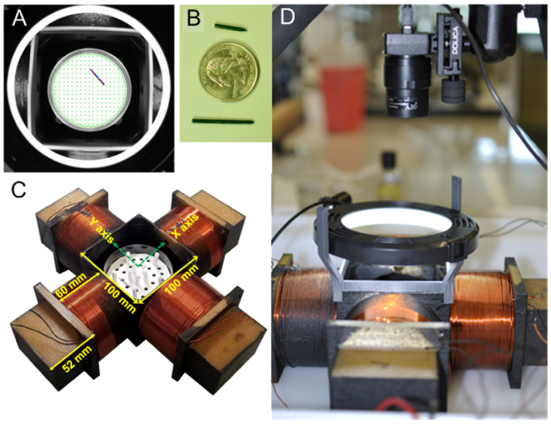
Pictures of magnetic steering system: (A) Example image of needle in Petri dish sample, (B) manipulated needles together with US 25 cent coin, (C) four coil manipulation array printed from ULTEM™1010 (Stratasys Direct) with wound coils, (D) overview image of magnetic needle steering system showing coil array with video camera and light source.
In this paper, we develop an autonomous magnetic needle steering controller for controlling magnetic suture needles in a 2-dimensional (2-D) viscous medium environment. To demonstrate the feasibility of accurate motion control of magnetic suture needles, we employ the electromagnetic system setup as shown in Fig. 1, which consists of four cardinally arranged coils (Fig. 1C), a camera for needle perception, and a ring light for illumination (Fig. 1D). A Petri dish filled with viscous liquid is used as the needle control environment. Although real suturing tasks for MIS require controlling needles in 3-dimensional (3-D) workspaces which are larger than that of our proposed system, this work demonstrates a proof of concept study and investigates the feasibility of autonomously controlling magnetic suture needles. It is an important initial step to move this idea towards real clinical application.
The primary contributions of this paper include the development of a magnetic needle steering controller that consists of four main components: 1) a mathematical model that represents magnetic force and torque applied on the needle; 2) a kinematically constrained dynamic model to guarantee the needle only translate along its central axis; 3) a feedback linearizing controller to compute the input currents of the coils for achieving desired velocity commands; and 4) closed-loop control schemes with different motion patterns. In addition, we implement the magnetic needle steering controller in our MagnetoSuture™ system to experimentally validate the performance of magnetic suture needle control.
II. Problem Formulation
We consider the problem of controlling the motion of a rigid cylindrical needle of length ℓndl = 18 mm and radius ρndl = 0.8 mm made of hard magnetic material (NdFeB, N42) with residual flux density . The needle is suspended in a viscous medium (polysorbate 80) with dynamic viscosity μd = 0.43 Pa-s inside a circular Petri dish of diameter 2rdom = 85 mm. We assume that the needle is uniformly magnetized and has a uniform mass distribution.
The needle is to be controlled through the application of external magnetic fields generated by an array of four uniformly spaced cylindrical electromagnets (EM). We adopt the same system configuration as the electromagnetic array developed in [15], whose centers are a distance of rem = 80 mm from the center of the dish and whose centerlines intersect at the center of the dish (Fig. 2). The electromagnets are composed of approximately 12 tightly wound layers of 54 turns of AWG 16 polyimide-coated copper wire (Nem = 12×54). The inner diameter of the EM is 85 mm, their outer diameter is 98 mm (average diameter 2ρem = 91.5 mm), and their length is ℓem = 60 mm.
Fig. 2.
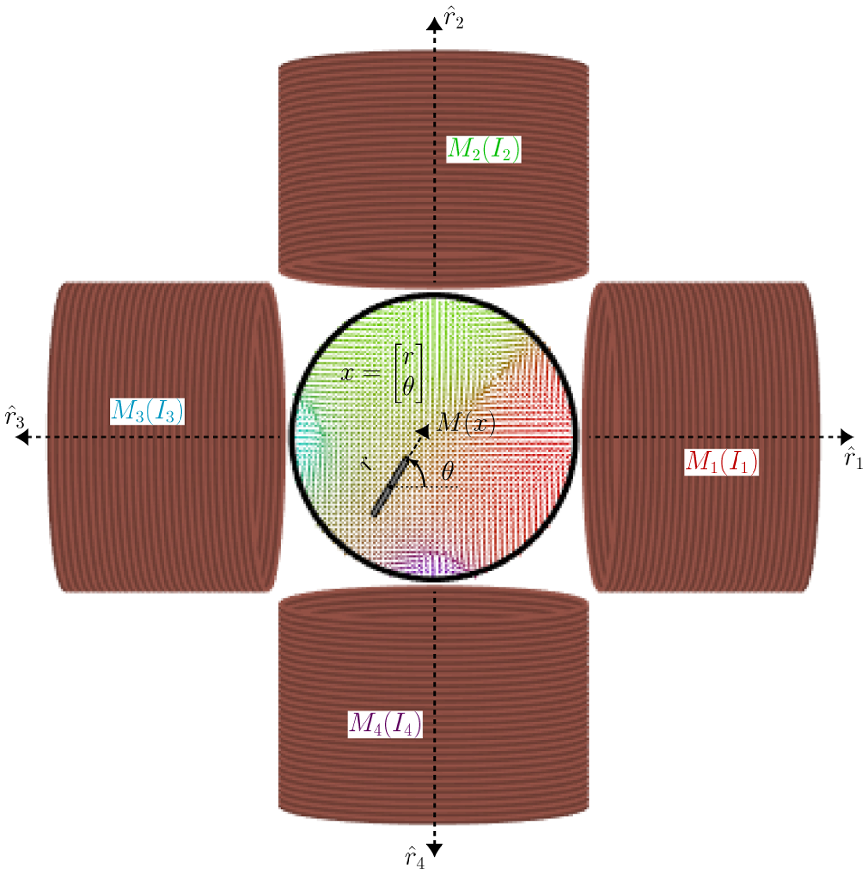
A magnetic needle is suspended in a viscous medium inside a circular Petri dish. Motion is achieved through interactions with the external magnetic fields generated by the four electromagnets whose currents can be controlled.
In the next section, we will discuss the effects of the external magnetic field generated by the EM on the needle’s motion, and use these to design controllers.
III. Magnetic Needle Steering Controller Design
In this section we will design a control strategy for tetherless manipulation of a magnetic needle. We begin by modeling the magnetic fields generated by the electromagnets.
A. Coordinate System
The domain of operation, the interior of the dish, will be denoted by as a circular area of radius rdom centered at the origin. Consider the general setting of m EM whose centers are located at , k ∈ {1, …, m}, and without loss of generality assume that they are uniformly spaced a distance rem = ∥rk∥ from the origin. As stated above, we assume these EM are aligned such that their axes of symmetry intersect at the origin, i.e., that their axes of symmetry are .
We wish to control the centroid of a needle r ∈ D and its heading (in the north pole direction) given by θ by manipulating external magnetic field acting on the needle through the controlled currents of the m EM. For convenience denote x = [rT, θ]T as the state of the needle.
B. Magnetic Fields, Forces, and Moments
Here we assume that the motion of a needle due to external magnetic field generated by the EM can be modeled through the interaction between magnetic dipoles [26]. Let the magnetization vector of the needle be
| (1) |
where μ0 = 4π × 10−7 H/m is the permeability of vacuum and h(θ) = [cos(θ), sin(θ)]T is the heading vector of the needle. The magnetization vectors for the EM will be modeled as
| (2) |
Let the vector from each EM to the needle’s centroid be given by
| (3) |
A dipole model is used for the magnetic field generated by the EM, given by
| (4) |
The resulting moment (off plane) is thus given by
| (5) |
where
| (6) |
| (7) |
The force exerted by the EM is given by the gradient of the magnetic potential [26]
| (8) |
where the argument to h(θ) was omitted.
C. Needle Dynamics
As was done in [24], we will assume first order dynamics for the needle due to laminar fluid flow from low Reynolds number and negligible inertia terms, resulting in
| (9) |
where the fluid drag constants will be approximated by those of an ellipsoid, i.e., σr ≈ (2πμdℓndl/ln(ℓndl/ρndl)) and .
To ensure that sufficient force can be exerted on the needle, we will impose the kinematic constraint
| (10) |
that is, that the needle can only translate along its axis. Thus, the linear velocity of the needle becomes
| (11) |
For convenience, we will similarly denote ω = τ/σθ as the angular velocity.
Let
| (12) |
such that if g(x) = [g1(x), ⋯, gm(x)] and I = [I1, ⋯, Im]T are stacked versions of these vector fields and EM currents, then we get
| (13) |
The kinematically constrained dynamics of the needle becomes
| (14) |
D. Feedback Linearizing Controller
We now propose a current controller to achieve desired velocity commands (vd, ωd). Define the mapping
| (15) |
for some . From (13), the actual linear and angular velocities may be expressed in terms of this mapping, i.e.,
| (16) |
As long as at least two of the fields generated by the EM are linearly independent at every r ∈ D, the matrix g(x)g(x)T will be full-rank. Thus, solving for the desired velocities yields
| (17) |
or in terms of our control currents
| (18) |
This is equivalent to finding the Moore-Penrose inverse of g(x) [27], which can be shown to be the optimal solution to the problem
| (19) |
E. Closed-Loop Control Schemes
Several different closed-loop control strategies are implemented using (18). The first strategy allows the needle to achieve tracking of a reference heading, given by
| (20) |
where kθ > 0 is a tuning parameter, θd is the desired reference heading.
The remaining strategies will perform tracking of a reference motion pattern encoded through time-varying positions rd(t) by setting
| (21) |
where kr > 0 is a tuning parameter, and mapping into linear and angular velocities via the transformation [28]
| (22) |
where λ > 0 is a tuning parameter to control the aggressiveness in which the controller favors turning to track the reference (e.g., λ = ℓndl/2 allows us to achieve the desired reference zd at the tip of the needle).
F. Needle Pose Estimation
In order to estimate the needle pose, we utilize a Hough Line Transform with appropriate pre-processing and post-processing. To prepare the image, we downscale the raw image, mask the circular work space of the dish, threshold the image to improve contrast, and apply a Gaussian filter. By using the trial-and-error method, we used a 0.5 scaling factor, a threshold value of 80, and a 9 × 9 Gaussian filter for our experiment. After processing, we extract edges using a Canny edge detector and generate a set of line estimates using the Probabilistic Hough Line Transform. Once we have collected our estimates, we remove outliers and apply an averaging function to predict the heading of the needle. For predicting position, we remove outliers and fit a line of best fit to the remaining lines. We compare this predicted line to the known length of the needle, and correct the length if the estimated needle length is too short. The center of this corrected needle estimate is used as our positional estimate.
This approach can be fine tuned by adjusting the maximum line gap parameter. For larger values of maximum line gap, we generate a set of long Hough Lines, and for smaller values, we generate a set of short Hough Lines. In general, the long Hough Lines approach produces fewer line estimates, and is more robust to visual noise, but is susceptible to returning an empty set if the maximum line gap is set too high. In contrast, the short Hough Lines approach produces a larger set of line estimates and is less likely to encounter an empty set, but is less robust to visual noise. In our implementation, we chose to use a hybrid approach which preferred to use results from long Hough Lines, but would switch to a short Hough Lines approach if the initial set was empty. Results from both approaches for estimating needle pose are shown in (Fig. 3).
Fig. 3.
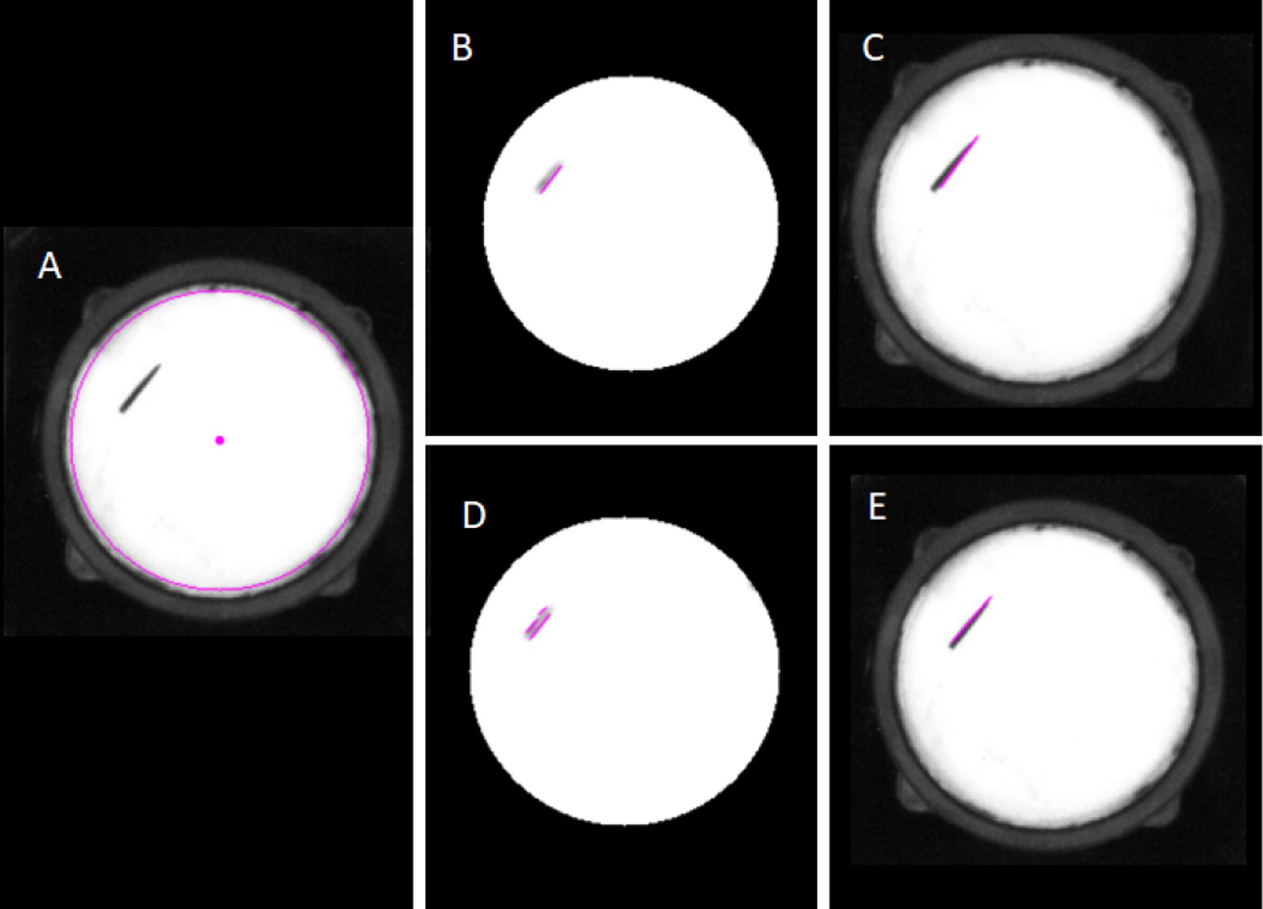
Needle pose estimations with long Hough Lines (B-C) and with short Hough Lines (D-E). (A) Raw image; (B) Long Hough Line Transform super-imposed on processed image; (C) Needle Pose estimation from long Hough Lines on original image; (D) Short Hough Line Transform super-imposed on processed image; (E) Needle Pose estimation from short Hough Lines on original image.
IV. Magnetic Needle Control Experiment
In this section we describe the implementation of the controller and pose estimation described in the previous sections. We begin discussion with the experimental setup, and proceed to quantify the tracking error for a sequence of experiments.
A. Experimental Setup
We adopt the same cube-shaped magnetic work space greater than 90 mm × 90 mm with the ability to generate sufficient force on a NdFeB needle [15]. The initial experiments are two-dimensional manipulations of our NdFeB needle taking place in a circular Petri dish. To improve detection of our needle for vision feedback, the needle is coated in dark green RUST-OLEUM Ultra Cover Paint + Primer spray paint, and a white sheet is attached to the bottom of the Petri dish to improve visual contrast between the needle and the background. Furthermore, to reduce needle detection errors, we added a 3D printed PLA mount to hold a ring light to illuminate the scene with consistent lighting. To capture images for needle pose estimation, we are using a Point Grey Chameleon CMLN-13S2C USB 2.0 Digital Camera with a maximum frame rate of 18 frames per second, and a resolution of 1296 × 964 pixels. The camera is attached to a tripod that hangs at a sufficient distant over the light to prevent glare.
In the following experiments, we control the needle rotation at different locations in the Petri dish, and control the needle position to recreate multiple motion patterns.
B. Needle Rotation Control
As described in Section III-E, for this motion pattern we set the controller as in (20) with θd as the desired heading. The red dots in Fig. 5 represent the 9 different locations for testing the needle rotation control accuracy. The coordinates of the locations are ➀:(−0.02 m, 0.02 m), ➁:(0 m, 0.02 m), ➂:(0.02 m, 0.02 m), ➃:(−0.02 m, 0 m), ➄:(0 m, 0 m), ➅:(0.02 m, 0 m), ➆:(−0.02 m, −0.02 m), ➇:(0 m, −0.02 m) and ➈:(0.02 m, −0.02 m). At each needle position, we run 7 separate rotation control tests by using different starting angles and target angles as illustrated in Fig. 5: 0 → π/4, π/4 → π/2, π/2 → 3π/4, 3π/4 → π, π → 5π/4, 5π/4 → 3π/2, 3π/2 → 7π/4. Angles are provided in radians.
Fig. 5.
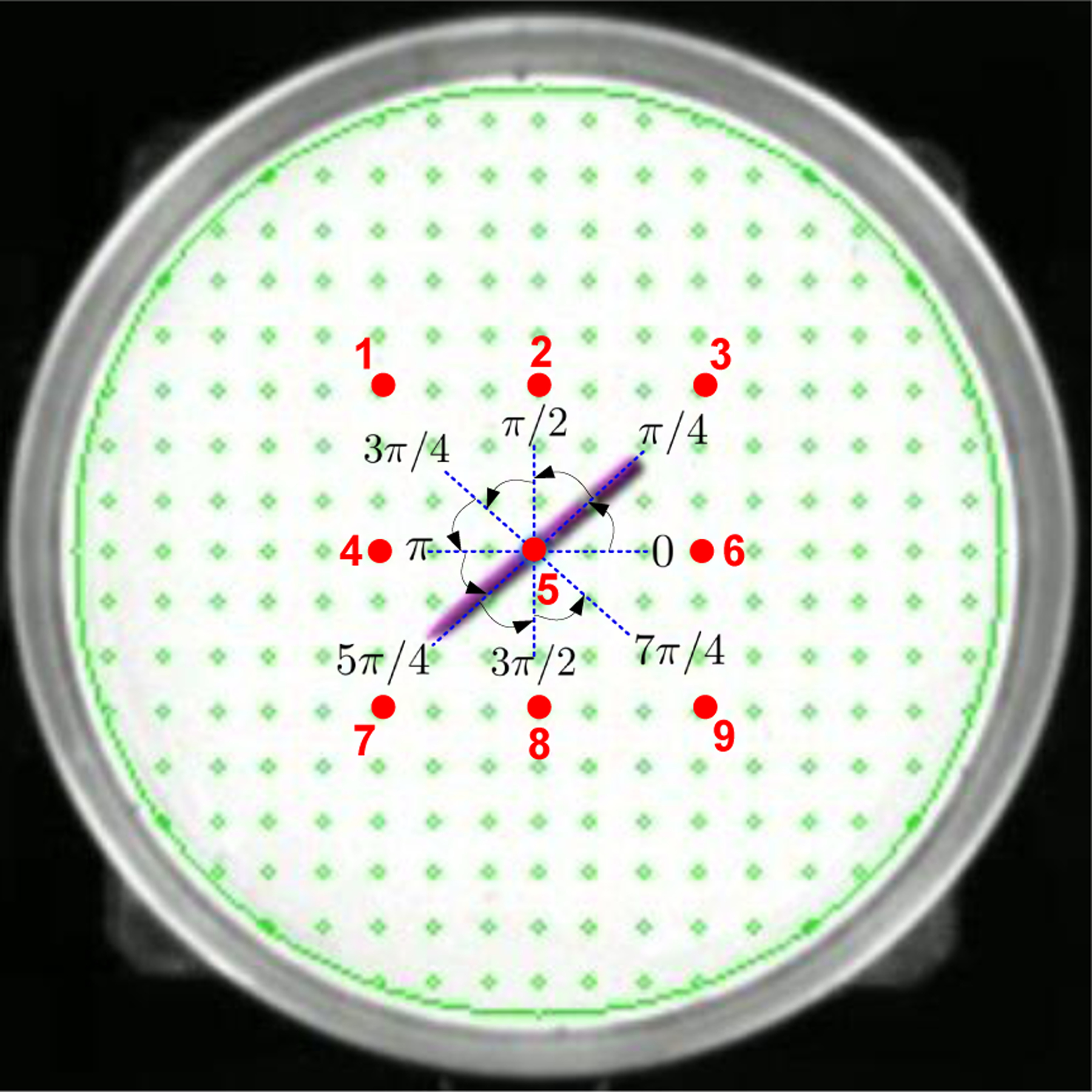
Experiment design of needle rotation control. The big circular region demonstrates the Petri dish. The red number indicates the locations for testing the needle rotation control. The angle intervals show starting angles and target angles of the needle.
The needle shown in Fig. 5 demonstrates the rotational control that started from angle π rad, and stopped at the target angle 5π/4 rad at the location ➄. Table I shows the needle rotation control errors between the target angles and the executed final angles to reflect the control accuracy. We calculated mean errors and standard deviation (SD) of the errors at each test location. We employed two metrics to quantify mean errors: mean absolute percentage error (MAPE) and mean absolute error (MAE). The results show MAPEs range from 0.14% to 2.5% and the MAEs range from 0.0019 rad to 0.0338 rad. The error SDs range from 0.0141 rad to 0.0347 rad.
TABLE I.
Needle Rotation Control Accuracy
| Test Location | Mean Absolute Percentage Error (%) | Mean Absolute Error (rad) | Error Standard Deviation (rad) |
|---|---|---|---|
| 1 | 0.14 | 0.0019 | 0.0141 |
| 2 | 1.52 | 0.0175 | 0.0188 |
| 3 | 1.31 | 0.0117 | 0.0187 |
| 4 | 2.50 | 0.0338 | 0.0232 |
| 5 | 0.94 | 0.0126 | 0.0301 |
| 6 | 1.36 | 0.0183 | 0.0192 |
| 7 | 2.14 | 0.0242 | 0.0240 |
| 8 | 1.79 | 0.0162 | 0.0347 |
| 9 | 1.97 | 0.0214 | 0.0225 |
C. Position Control using Discretized Trajectories
In this section, we implemented a simplified version of the closed-loop controller based on (20) and (21) by taking out the first order derivatives from (20) and from (21). We discretized several motion trajectories and commanded the needle to follow the pathway points. In Fig. 6, we demonstrate controlling the needle position (Fig. 6A) to follow four different trajectories, including square trajectory, circular trajectory, number “8” trajectory and purse-string suture pattern trajectory.
Fig. 6.
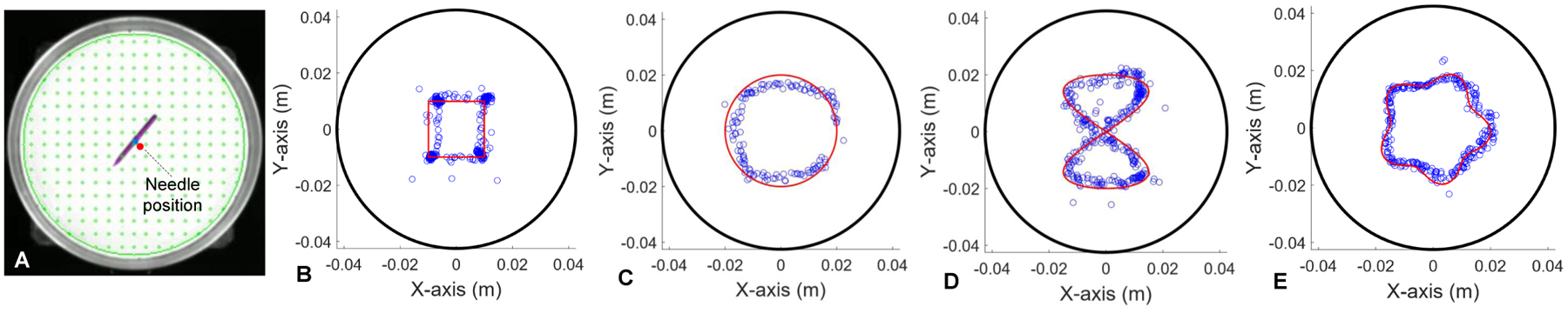
Needle position control experiments. (A) Estimated needle position in the Petri dish by using optical visual perception. (B) Square trajectory position control. (C) Circular trajectory position control. (D) Number “8” trajectory position control. (E) Purse-string trajectory position control. The black circles in (B)-(E) represent the edge of Petri dish. The red lines represent the planned trajectories. The blue dots represents the executed trajectories.
1). Square Trajectory:
As shown in Fig. 6B, the square trajectory was generated by specifying four corner points: (−0.01 m, −0.01 m), (0.01 m, −0.01 m), (0.01 m, 0.01 m) and (−0.01 m, 0.01 m). Additionally, we specified a θd to adjust the rotation after each corner point to improve the sharpness of the motion path at the corners.
For the following more complex trajectories, we generated a set of target points for the needle to seek out in order. When the positional error between the needle and the target point was below a chosen threshold value δr, we incremented the desired position rd to the subsequent target point. For non-smooth curves, we introduced an additional heading adjustment phase between the positional adjustment steps using (20) to adjust to a desired θd value. This process was continued until the trajectory is completed.
2). Circular Trajectory:
Fig. 6C demonstrates the needle to track a circular trajectory characterized by the radius R = 0.02 m. The trajectory is represented as follows:
| (23) |
where N is the total number of pathway points, n denotes index of the pathway points. Again, the red lines in Fig. 6C represent the planned path, and blue dots represent the executed trajectory of the needle.
3). Number “8” Trajectory:
A number “8” pattern can be parameterized as
| (24) |
where Rx=0.015 m and Ry=0.02 m are scaling factors for the pattern shown in Fig. 6D.
4). Purse-String Suture Pattern Trajectory:
The purse-string suture pattern is defined parametrically by the following equation
| (25) |
where Rmax = 0.02 m and Rmin = 0.015 m are the maximum and minimum radii of the pattern. md = 5 represents the number of “stitches” of the purse-string suture pattern as shown in Fig. 6E.
To better visualize the results of position control for tracking different trajectories illustrated in Fig. 6, we plot the needle positions and heading angles versus time as shown in Fig. 7 for each of the trajectories. For quantifying the position tracking performance, the position tracking errors are computed and plotted in Fig. 8. The root mean square (RMS) errors are 1.6 mm (Fig. 8A), 2.7 mm (Fig. 8B), 2.1 mm (Fig. 8C) and 1.5 mm (Fig. 8D) respectively. In the following section, we provide the experiment results for controlling the needle velocity and subsequently controlling the needle position by using time-varying trajectories.
Fig. 7.
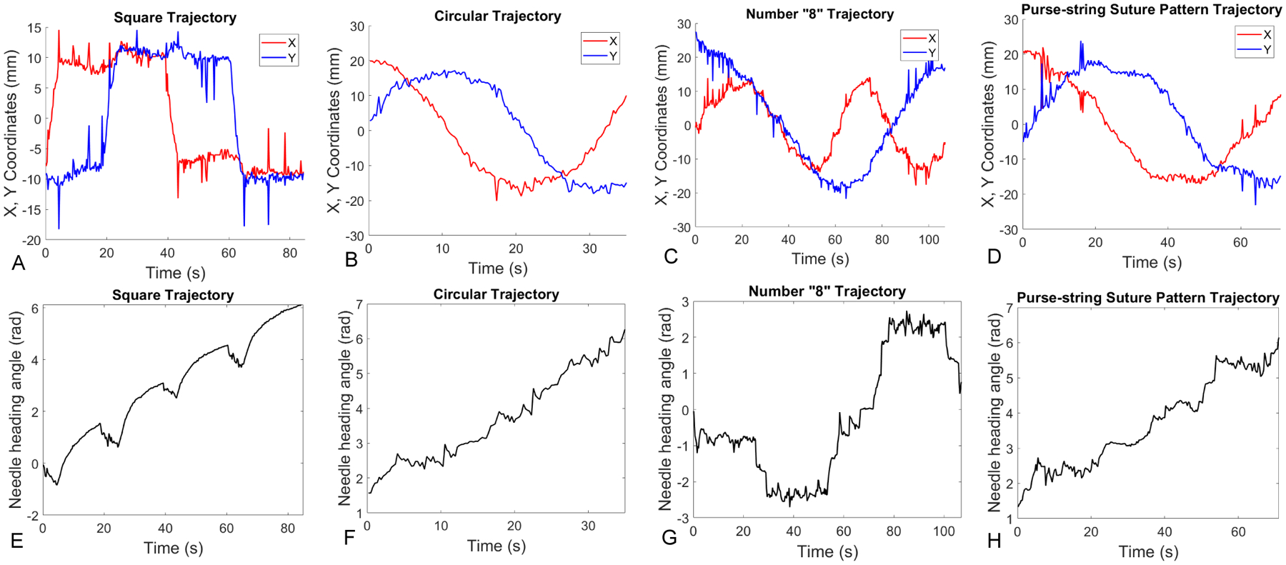
Plots of needle positions and angles versus time. (A)-(D) show X, Y coordinates versus time when the needle tracks square, circular, number “8”, and purse-string suture pattern trajectories. Similarly, (E)-(H) show the needle heading angles versus time in different trajectory tracking tasks.
Fig. 8.
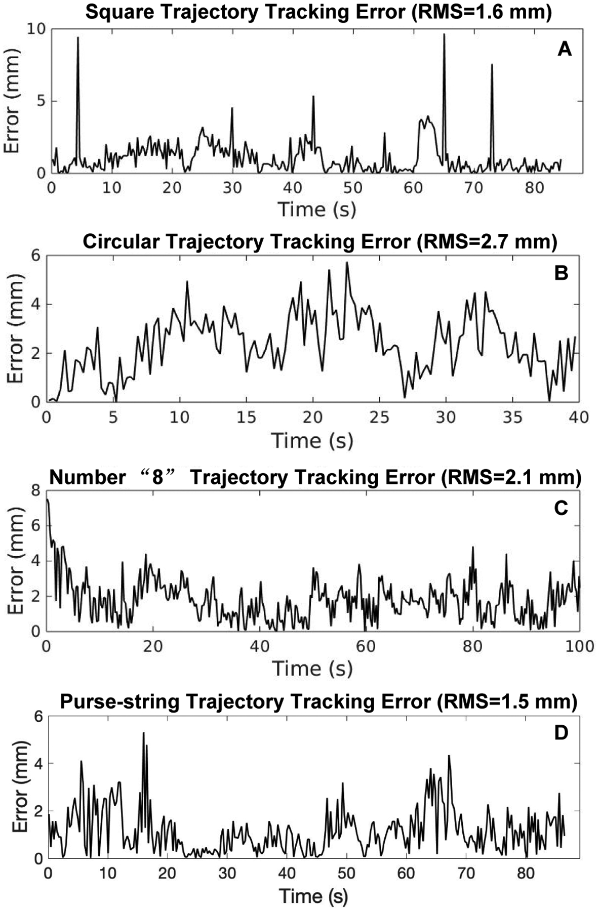
Tracking errors of different discretized trajectories. (A) Square trajectory tracking error with the root mean square (RMS) value as 1.6mm. (B) Circular trajectory tracking error with RMS=2.7mm. (C) Number “8” trajectory tracking error with RMS=2.1mm. (D) Purse-string suture pattern trajectory tracking error with RMS=1.5mm.
D. Velocity Control using Time-Varying Trajectories
In this experiment, we use the closed-loop control schemes in (20) and (21) to control the needle. Here we only demonstrate a time-varying circular trajectory, which is defined by the following equation
| (26) |
where R = 0.02 m denotes the circle radius, Td = 95 s is the total time it takes to perform motion as shown in Fig. 9. Its derivative is given by
| (27) |
Fig. 9.
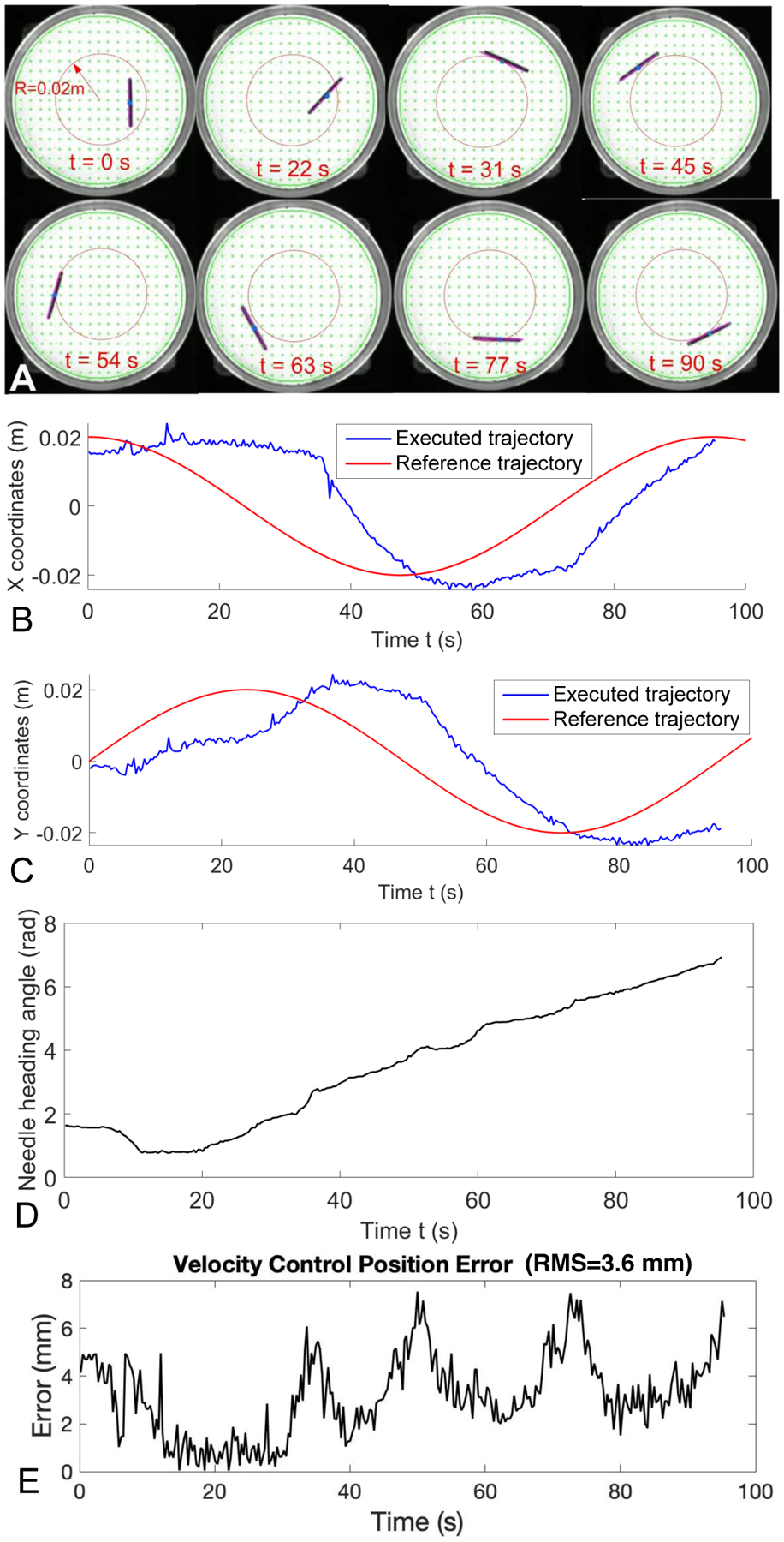
Velocity control of magnetic suture needle by following a time-varying circular trajectory. (A) Needle positions at different time frames. (B) Comparison of reference and executed trajectory in the X coordinate versus time. (C) Comparison of the reference and executed trajectory in the Y coordinate versus time. (D) Needle heading angle from executed trajectory. (E) Position error of the executed trajectory.
Fig. 9A shows the needle poses at a sequence of time frames when the needle was following a time-varying circular trajectory with R = 0.02 m. Fig. 9B and Fig. 9C show a comparison of the reference and executed trajectories in the X and Y coordinates versus time, respectively. Fig. 9D shows the needle heading angle versus time. Fig. 9E demonstrates the position errors with RMS=3.6 mm for tracking the circular trajectory by using the velocity control scheme.
V. Conclusion
In this paper we developed a magnetic needle steering controller for autonomous control of magnetic suture needles. We controlled a magnetic needle in a Petri dish filled with viscous liquid by using a four-coil electromagnetic system. To test the needle controller, we conducted rotation control, position control for tracking discretized trajectories, and velocity control for tracking a time-varying trajectory. The rotation control demonstrated a maximum of 2.5% mean absolute percentage error, and a maximum of 0.0338 rad of mean absolute error at 9 different locations in the Petri dish. The position tracking RMS errors range from 1.5 mm to 2.7 mm in four different cases of discretized trajectories,including square, circular, number “8”, and purse-string suture pattern trajectories. The RMS error for tracking a time-varying trajectory is 3.6 mm. The experiment results demonstrate that the proposed controller is capable of actuating mesoscale magnetic needles with well-controlled accuracy for both rotational motion and translational motion. In our future study, we plan to demonstrate a few autonomous suturing applications based on our existing system and the proposed magnetic needle controller.
Fig. 4.
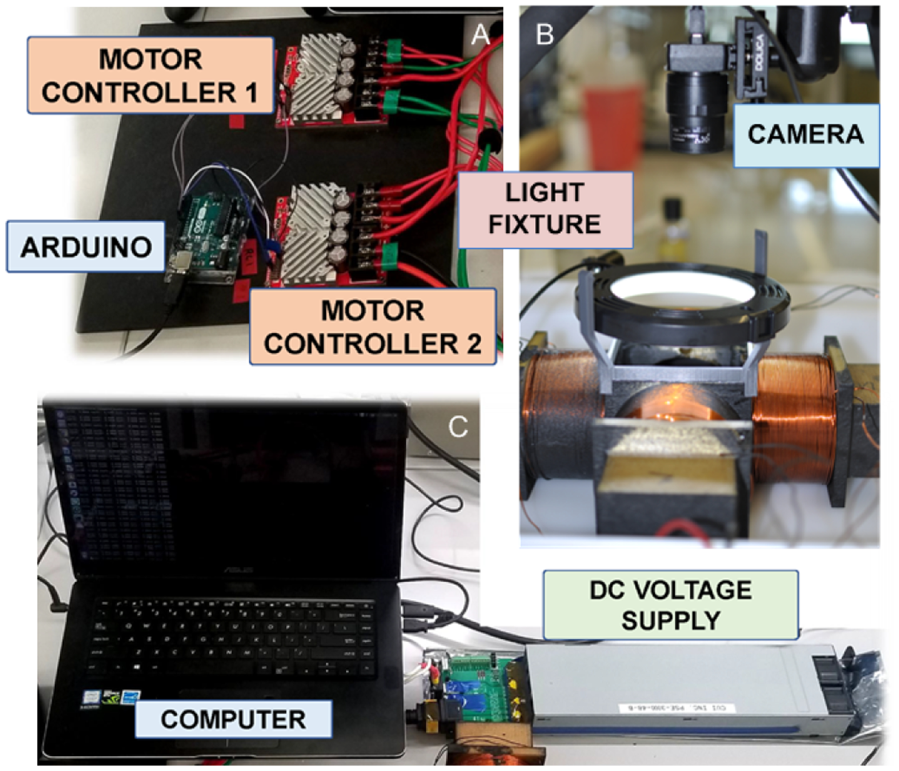
Hardware setup for current controller, electromagnetic system, and visual perception system. An Arduino Uno (A) regulates current through two motor controllers that are connected to a DC voltage supply (C). A circular light in (B) is mounted over the coils to provide sufficient lighting for the computer vision to operate.
Acknowledgments
This paper was supported by the University of Maryland Medical Device Development Fund (MDDF) and the National Institute of Biomedical Imaging and Bioengineering (NIBIB) of the National Institutes of Health under award number R01EB020610.
References
- [1].Tsui C, Klein R, and Garabrant M, “Design of a magnetic actuated fully insertable robotic camera system for single-incision laparoscopic surgery,” Surg Endosc, vol. 27, pp. 2253–2257, 2013. [DOI] [PubMed] [Google Scholar]
- [2].Intuitive Surgical, Inc., “da vinci sp,” https://www.intuitivesurgical.com/sp/, [Online; accessed 28-February-2020]. [Online]. Available: https://www.intuitivesurgical.com/sp/
- [3].Titan Medical, Inc., “Sport surgical system,” http://titanmedicalinc.com/technology/, [Online; accessed 28-February-2020]. [Online]. Available: http://titanmedicalinc.com/technology/
- [4].Simaan N, Yasin RM, and Wang L, “Medical technologies and challenges of robot-assisted minimally invasive intervention and diagnostics,” Annual Review of Control, Robotics, and Autonomous Systems, vol. 1, no. 1, pp. 465–490, 2018. [Google Scholar]
- [5].Gandaglia G, Ghani KR, Sood A, Meyers JR, Sammon JD, Schmid M, Varda B, Briganti A, Montorsi F, Sun M, Menon M, Kibel AS, and Trinh Q-D, “Effect of Minimally Invasive Surgery on the Risk for Surgical Site Infections: Results From the National Surgical Quality Improvement Program (NSQIP) Database,” JAMA Surgery, vol. 149, no. 10, pp. 1039–1044, 10 2014. [DOI] [PubMed] [Google Scholar]
- [6].Liu X, Mancini GJ, and Tan J, “Design of a unified active locomotion mechanism for a capsule-shaped laparoscopic camera system,” in 2014 IEEE International Conference on Robotics and Automation (ICRA), May 2014, pp. 2449–2456. [Google Scholar]
- [7].Simi M, Silvestri M, Cavallotti C, Vatteroni M, Valdastri P, Menciassi A, and Dario P, “Magnetically activated stereoscopic vision system for laparoendoscopic single-site surgery,” IEEE/ASME Transactions on Mechatronics, vol. 18, no. 3, pp. 1140–1151, June 2013. [Google Scholar]
- [8].Liu X, Mancini GJ, Guan Y, and Tan J, “Design of a magnetic actuated fully insertable robotic camera system for single-incision laparoscopic surgery,” IEEE/ASME Transactions on Mechatronics, vol. 21, no. 4, pp. 1966–1976, August 2016. [Google Scholar]
- [9].Rivas H, Robles I, Riquelme F, Vivanco M, Jiménez J, Marinkovic B, and Uribe M, “Magnetic Surgery: Results from First Prospective Clinical Trial in 50 Patients,” Annals of Surgery, vol. 267, no. 1, pp. 88–93, 2018. [DOI] [PMC free article] [PubMed] [Google Scholar]
- [10].Garbin N, Di Natali C, Buzzi J, De Momi E, and Valdastri P, “Laparoscopic Tissue Retractor Based on Local Magnetic Actuation,” Journal of Medical Devices, vol. 9, no. 1, 2015. [Google Scholar]
- [11].Petruska AJ, Ruetz F, Hong A, Regli L, Surucu O, Zemmar A, and Nelson BJ, “Magnetic needle guidance for neurosurgery: Initial design and proof of concept,” Proceedings - IEEE International Conference on Robotics and Automation, vol. 2016-June, pp. 4392–4397, 2016. [Google Scholar]
- [12].Muller L, Saeed M, Wilson MW, and Hetts SW, “Remote control catheter navigation: Options for guidance under MRI,” Journal of Cardiovascular Magnetic Resonance, vol. 14, no. 1, pp. 1–9, 2012. [DOI] [PMC free article] [PubMed] [Google Scholar]
- [13].Sitti M, Ceylan H, Hu W, Giltinan J, Turan M, Yim S, and Diller E, “Biomedical applications of untethered mobile milli/microrobots,” Proceedings of the IEEE, vol. 103, no. 2, pp. 205–224, February 2015. [DOI] [PMC free article] [PubMed] [Google Scholar]
- [14].Shademan A, Decker RS, Opfermann JD, Leonard S, Krieger A, and Kim P, “Supervised autonomous robotic soft tissue surgery,” Science Translational Medicine, vol. 8, no. 337, pp. 337ra64–337ra64, 2016. [Online]. Available: http://stm.sciencemag.org/cgi/doi/10.1126/scitranslmed.aad9398 [DOI] [PubMed] [Google Scholar]
- [15].Mair LO, Liu X, Dandamudi B, Jain K, Chowdhury S, Weed J, Diaz-Mercado Y, Weinberg IN, and Krieger A, “Magnetosuture: Tetherless manipulation of suture needles,” IEEE Transactions on Medical Robotics and Bionics, accepted. [Online]. Available: 10.13140/RG.2.2.13316.88961 [DOI] [PMC free article] [PubMed] [Google Scholar]
- [16].Cao Q, Fan Q, Chen Q, Liu C, Han X, and Li L, “Recent advances in manipulation of micro- and nano-objects with magnetic fields at small scales,” Mater. Horiz, pp. –, 2020. [Online]. Available: 10.1039/C9MH00714H [DOI] [Google Scholar]
- [17].Rahmer J, Stehning C, and Gleich B, “Remote magnetic actuation using a clinical scale system,” PLoS ONE, vol. 13, no. 3, p. e0193546, 2018. [DOI] [PMC free article] [PubMed] [Google Scholar]
- [18].Mahoney AW, Nelson ND, Parsons EM, and Abbott JJ, “Non-ideal behaviors of magnetically driven screws in soft tissue,” in 2012 IEEE/RSJ International Conference on Intelligent Robots and Systems, October 2012, pp. 3559–3564. [Google Scholar]
- [19].Jeon S, Hoshiar A, Kim K, Lee S, Kim E, Lee S, Kim J, Nelson B, Cha H, Yi B, and Choi H, “A magnetically controlled soft microrobot steering a guidewire in a three-dimensional phantom vascular network,” Soft Robot, vol. 6, no. 1, 2019. [DOI] [PMC free article] [PubMed] [Google Scholar]
- [20].Heunis C, Sikorski J, and Misra S, “Flexible instruments for endovascular interventions: Improved magnetic steering, actuation, and image-guided surgical instruments,” IEEE Robotics Automation Magazine, vol. 25, no. 3, pp. 71–82, September. 2018. [Google Scholar]
- [21].Yeow BS and Hongliang R, “Magnetic Actuated Catheterization Robotics,” in Electromagnetic Actuation and Sensing in Medical Robotics, Ren H and Sun J, Eds. Springer Nature Sinapore Pte Ltd. 2018, 2017, ch. Magnetic A, pp. 73–103. [Google Scholar]
- [22].Kummer MP, Abbott JJ, Kratochvil BE, Borer R, Sengul A, and Nelson BJ, “Octomag: An electromagnetic system for 5-dof wireless micromanipulation,” IEEE Transactions on Robotics, vol. 26, no. 6, pp. 1006–1017, December 2010. [Google Scholar]
- [23].Diller E, Giltinan J, and Sitti M, “Independent control of multiple magnetic microrobots in three dimensions,” The International Journal of Robotics Research, vol. 32, no. 5, pp. 614–631, 2013. [Google Scholar]
- [24].Salehizadeh M and Diller E, “Two-agent formation control of magnetic microrobots in two dimensions,” Journal of Micro-Bio Robotics, vol. 12, no. 1–4, pp. 9–19, 2017. [Google Scholar]
- [25].Ilami M, Ahmed R, Petras A, Beigzadeh B, and Marvi H, “Magnetic needle steering in soft phantom tissue,” Sci Rep, vol. 10, no. 2500, 2020. [DOI] [PMC free article] [PubMed] [Google Scholar]
- [26].Yung KW, Landecker PB, and Villani DD, “An analytic solution for the force between two magnetic dipoles,” Physical Separation in Science and Engineering, vol. 9, no. 1, pp. 39–52, 1998. [Google Scholar]
- [27].Kolavennu S, Palanki S, and Cockburn J, “Nonlinear control of nonsquare multivariable systems,” Chemical Engineering Science, vol. 56, no. 6, pp. 2103–2110, 2001. [Google Scholar]
- [28].Olfati-Saber R, “Near-identity diffeomorphisms and exponential /spl epsi/-tracking and /spl epsi/-stabilization of first-order nonholonomic se(2) vehicles,” in Proceedings of the 2002 American Control Conference (IEEE Cat. No.CH37301), vol. 6, May 2002, pp. 4690–4695 vol.6. [Google Scholar]