

Abstract
The nonlinear response of a material to an external stimulus is vital in fundamental science and technical applications. The power-law current–voltage relationship of a varistor is one such example. An excellent example of such behavior is the power-law current–voltage relationship exhibited by Bi2O3-doped ZnO varistor ceramics, which are the cornerstone of commercial varistor materials for overvoltage protection. Here, we report on a sustainable, ZnO-based varistor ceramic, without the volatile Bi2O3, that is based on Cr2O3 as the varistor former and oxides of Ca, Co, and Sb as the performance enhancers. The material has an ultrahigh α of up to 219, a low IL of less than 0.2 μA/cm2, and a high Eb of up to 925 V/mm, making it superior to state-of-the-art varistor ceramics. The results provide insights into the design of materials with specific characteristics by tailoring states at the grain boundaries. The discovery of this ZnO-Cr2O3-type varistor ceramic represents a major breakthrough in the field of varistors for overvoltage protection and could drastically affect the world market for overvoltage protection.
Keywords: ZnO, Cr2O3, varistor ceramics, double-Schottky barriers, microstructure, I−V characteristics
Introduction
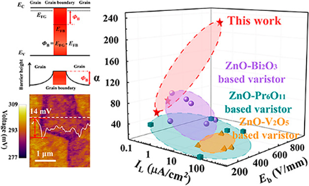
Varistors, better described as variable resistors, are used in billions of low-power electronic devices and heavy-duty electrical-energy-distribution systems to protect circuits from transient voltage surges by means of their nonlinear current–voltage (I–V) characteristics.1−3 Specifically, a varistor is highly resistive at a low applied voltage but becomes conductive very quickly when the applied voltage exceeds a material-specific threshold known as the breakdown voltage Eb. Above Eb, the nonlinear I–V characteristics are empirically described by a power-law function I = bVα, where b is a constant and α is a nonlinear coefficient. The value of α is thus a gauge of how responsive the varistor is to the transient voltage surge. As illustrated in Figure 1a, the value of α is physically governed by the height of the double-Schottky barrier (DSB), φB, at the grain boundary (GB);4,5 φB = |EFB – EFG|, where EFB and EFG are the Fermi levels in the GB and the grain, respectively. Besides the high α value, a high-performance varistor entails a small leakage current (IL), which is the current at 0.75 × Eb. Low values of IL ensure a low chance of thermal runaway, good stability and aging behavior, and also a low power consumption.6
Figure 1.

High-performance ZnO-based varistors. (a) Schematic diagram of the double-Schottky barriers (DSB) at the grain boundaries (GBs), where EC is the conduction band, EV is the valence band, and φB is the Schottky barrier height, which governs the nonlinear I–V characteristics. (b) Nonlinear coefficients (α) vs leakage currents (IL) and breakdown voltage (Eb) of ZnO-based varistors developed in this work. Literature data of ZnO-based varistors are listed for comparison.10−12,14−25
Among the metal–oxide varistors (MOVs) that are the state-of-the-art varistors, ZnO-based varistors have the highest DSB heights φB and superior nonlinear properties (high α values and low IL values).6 Note that pristine ZnO displays a very weak, nonlinear I–V characteristic, reflecting EFB and EFG that are nearly equal. It takes varistor former(s), also known as varistor activator(s), to create defect complexes at the GB, which shift the EFB to a deeper position in the band gap, and the resulting φB gives rise to the DSB and in turn elicits nonlinear I–V characteristics in the ZnO.5 In parallel with the varistor former(s) implemented at the GB, performance enhancer(s) can be doped into the grains to actively raise the EFG and thus increase φB to higher α and smaller IL values.6−8
Other than α and IL, a high Eb value is desired for surge protection and a reduction of device size in high-voltage dc power transmission and heavy-duty power-supply systems, thereby broadening the scope of applications. However, the increase of Eb tends to worsen α and IL simultaneously.3,9 As a result, the state-of-the-art ZnO-based varistors, with varistor formers such as Bi2O3, Pr6O11, and V2O5 along with their corresponding performance enhancers, such as Sb, Co, Mn, Ni, and Cr, typically achieve an α value of less than 60, an IL values higher than 1 μA/cm2, and an Eb value in the range 200–500 V/mm.10−12
After exploring a large phase space (Supporting Information), here we report on a novel ZnO-based varistor ceramic that uses Cr as the varistor former and Ca, Co, and Sb as the performance enhancers. These ceramics have record-high nonlinear characteristics, manifested in an ultrahigh α value up to 219, a very low IL value of less than 0.2 μA/cm2, and a high Eb value of 925 V/mm, making them superior to today’s varistor ceramics. For conciseness, we only list the performance of ZnO-based varistors for comparison in Figure 1b. Moreover, the materials sustainability (volatility and toxicity) of these ultrahigh-performance varistors is significantly improved. Specifically, the compositions avoid the use of highly volatile bismuth oxide,13 expensive rare earths like praseodymium, or the toxic vanadium oxide.
Experimental Section
Sample Preparation
Reagent-grade powders of ZnO, Cr2O3, CaCO3, Co3O4, and Sb2O3 were used for preparation of the materials. Cr-added ZnO with nominal compositions of (1 – x) mol ZnO-x mol Cr2O3 (x = 0.05%, 0.1%, 0.2%, 0.3%, and 0.4%, namely, ZnO-xCr2O3), Ca-doped ZnO-0.1% Cr2O3 (Zn0.979Cr0.002Ca0.02O1.002, aka 97.9 mol % ZnO + 0.1 mol % Cr2O3 + 2 mol % CaCO3 in raw materials), (Co, Ca)-codoped ZnO-0.1%Cr2O3 (Zn0.974Cr0.002Ca0.02Co0.015O1.017, aka 97.4 mol % ZnO + 0.1 mol % Cr2O3 + 2 mol % CaCO3 + 0.5 mol % Co3O4 in raw materials), (Co, Ca, Sb)-doped ZnO-0.1% Cr2O3 (Zn0.9725Cr0.002Ca0.02Co0.015Sb0.003O1.02, aka 97.25 mol % ZnO + 0.1 mol % Cr2O3 + 2 mol % CaCO3 + 0.5 mol % Co3O4 + 0.15 mol % Sb2O3 in raw materials), and (Co, Ca)-codoped ZnO (Zn0.975Ca0.02Co0.015O1.015, aka 97.5% mol ZnO + 2 mol % CaCO3 + 0.5 mol % Co3O4 in raw materials) ceramics were synthesized by a conventional solid-state technique. We used CaCO3 instead of CaO because CaO is not stable in air. At high temperatures, CaCO3 was decomposed to CaO and CO2 gas and then Ca is doped into ZnO. The starting powders were wet mixed by ball milling for 8 h, followed by drying at about 120 °C for 5 h, calcining at 450 °C for 2 h, and then cold pressed as pellets with a diameter of 12 mm and thickness of 1 mm. Finally, the pellets were sintered at 1200 °C for 3 h. Silver pastes were covered on the sample’s opposite surfaces and then dried at 560 °C for 15 min as electrodes.
Characterization
X-ray diffraction using Cu Kα radiation (D/max 2550 V, Rigaku, Tokyo, Japan) was used to analyze the phase purity. Microstructural observations were carried out on the polished surfaces using a field-emission scanning electron microscope (Magellan 400, FEI Co., USA). Energy-dispersive X-ray spectroscopy (Oxford Instrument, UK) was performed to detect elements and distributions. Spherical aberration-corrected transmission electron microscopy (HF 5000, Hitachi, Japan) with energy-dispersive X-ray spectroscopy (Oxford X-Max 100TLE, UK) and transmission electron microscopy (Tecnai-F20, FEI Co., USA) were used to observe the microstructures and compositions of the grain boundaries (GBs). The micro-Raman spectra were recorded with a Renishaw InVia Confocal micro-Raman system using the 532 nm line as an excitation source. The I–V curves were recorded with a high-voltage digital sourcemeter (Keithley 2410, Keithley Instruments Inc., USA). By convention, the breakdown voltage (Eb) was measured at a current of 1 mA/cm2, and the leakage current density (IL) was measured at an electric field of 0.75 × Eb. The nonlinear coefficient (α) was fitted by the equation I = bVα when the voltage is larger than Eb. The dielectric spectra were measured using a broad-band dielectric spectrometer (NovoControl, Hundsangen, Germany) in the frequency range from 0.1 Hz to 1 MHz with an amplitude voltage of 1 V. Ag paste (fired at 560 °C for 15 min) electrodes were used. The dc conductivity (f < 1 Hz) was obtained with dielectric spectroscopy at f = 0.1. The data from the impedance measurements were analyzed using the commercial software (Z-VIEW, version 3.1). Kelvin probe force microscopy (KPFM) measurements were performed on the atomic force microscopy (AFM) platform to observe the surface potential images. An ac modulation voltage of 2 V at 55 kHz in the lift mode with a distance of approximately 10 nm between the tip and the sample and a conductive Pt/Ir-coated tip (PR-EX-KPFM-5) were used. Additional information is available from the Wiley Online Library or from the author.
Results and Discussion
Unlike previous reports, Cr is, in this work, found to be a varistor former rather than a performance enhancer for ZnO-based varistors. Cr was thought to be a performance enhancer and, in this role, together with other performance enhancers (i.e., Sb, Co, Mn, Ni, etc.) was added to ZnO along with the well-established varistor formers such as Bi and Pr.17,19 To verify whether Cr is a varistor former at the GB or a performance enhancer in the grains, a series of samples with nominal compositions Zn1–xCr2xO1+2x was synthesized. The X-ray powder-diffraction measurements (Figure S1) reveal that a pure hexagonal wurtzite structure is obtained when x ≤ 0.1%, above which a secondary phase, ZnCr2O4, forms. These arguments are corroborated by the backscattered electron (BSE) micrographs and the energy-dispersive X-ray spectroscopy (EDS) measurements (Figure S2). As shown in Figure 2a, no intergranular phases or amorphous regions are observed at the GB by high-resolution transmission electron microscopy (HRTEM). While no Cr is detected in the grains, within the EDS detection limit, for all of the samples (Figure S2) Cr is observed at the GB (inset of Figure 2a). Micro-Raman spectra also detect a strong vibration mode centered at ∼830 cm–1, which was previously reported in Cr-added ZnO nanocrystals,26 at the GB, but absent in the grains (Figure 2b). All of the data suggest a preference for Cr to stay at the GB instead of in the grain. Meanwhile, the oxygen content is higher while the Zn content is lower at the GB compared to within the grain, indicating that the segregation of the Cr at the GBs leads to an O-rich GB compared to the grain (Figure S3). In light of the case study of ZnO-Bi2O3-based and ZnO-Pr6O11-based varistors,27,28 the segregation of Cr at the GB leads to the formation of a CrZn + VZn + Oi defect complex, which acts as a varistor former to shift the EFB to a deeper position in the band gap to yield the DSBs and thus the nonlinear characteristics (Figure 2c).
Figure 2.

Microstructures and electrical properties of Cr-added ZnO-based varistors. (a) High-resolution transmission electron microscopy (HRTEM) image of the grain boundary (GB) of 0.2% Cr-added ZnO. (Inset) Energy-dispersive X-ray spectroscopy (EDS) analysis of the GB. (b) Micro-Raman spectra of the grain and the GB of the 0.2% Cr-added ZnO. (c) J–E characteristics of the Cr-added ZnO varistors with different performance enhancers. Solid lines are the fitting results using the equation I = bVα. (d) Nonlinear coefficient α against the number of performance enhancers in the Cr-added ZnO-based varistors. Some literature data are listed for comparison.12,14,17−19,22−24,29,31−33
The varistor former Cr elicits nonlinear I–V characteristics in ZnO, but the α value is only about 2 in the ZnO-0.1% Cr2O3 sample (Figure 2c). Introducing performance enhancers is thus a must to enlarge the difference between EFB and EFG, i.e., φB. To this end, the results of our study show that codoping with Ca, Co, and Sb acts as an effective performance enhancer in the presence of the varistor former Cr. Figure S4a, which shows elemental mapping, indicates that Ca, Co, and Sb are homogeneously distributed in the grains in the absence of Cr within the EDS detection limit. Hereafter, the chemical formula (Ca, Co, Sb)-doped ZnO with a varistor former derived from x% Cr2O3 will be written in the form (Ca, Co, Sb)-doped ZnO-x% Cr2O3.
Figure 2c shows that the nonlinear current density vs. electric field (J–E) characteristics are observed in all of the Cr-added ZnO ceramics, but the α values vary by several orders of magnitude with the specific compositions of the performance enhancers (Table 1). The detailed electrical properties (α, IL and Eb, shown in Tables S1–S3) of the ZnO ceramics with various Ca-, Co-, and Cr-doping ratios are presented in the Supporting Information. In the following, we will focus on the samples with 0.1 mol % Cr2O3, 2 mol % CaCO3, 0.5 mol % Co3O4, and 0.15 mol % Sb2O3 ratios as an illustration and for conciseness. As shown in Figure 2d and Table 1, the α value increases from about 2 for ZnO-0.1% Cr2O3, to 27 for Ca-doped ZnO-0.1% Cr2O3, to 73 for (Ca, Co)-codoped ZnO-0.1% Cr2O3, and finally to an exceptional value of 219 in (Ca, Co, Sb)-codoped ZnO-0.1% Cr2O3. It is not rare to observe increased α values with an increasing number of enhancers (dopants);29 however, the magnitude of the improvement attained here is unprecedented (Figure 2d). Importantly, the (Ca, Co, Sb)-codoped ZnO-0.1% Cr2O3 ceramic has a very low IL of less than 0.2 μA/cm2, also superior to those of previous state-of-the-art varistors (Figure 1b).12,16,18,19 Furthermore, a high Eb of 925 V/mm is obtained in the (Ca, Co, Sb)-codoped ZnO-0.1% Cr2O3 ceramic due to the greatly decreased grain size (Figure S5).
Table 1. Electrical properties of Cr-added ZnO varistor ceramics with different performance enhancers.
| sample | α | IL (μA/cm2) | Eb (V/mm) |
|---|---|---|---|
| ZnO-0.1%Cr2O3 | 2 | ||
| Ca-ZnO-0.1%Cr2O3 | 27 | 8.6 | 424 |
| (Ca,Co)-ZnO-0.1%Cr2O3 | 73 | <0.2 | 394 |
| (Ca,Co,Sb)-ZnO-0.1%Cr2O3 | 219 | <0.2 | 925 |
The very low IL and greatly decreased grain size suggest a high GB resistance. This argument is corroborated by the results of impedance spectroscopy. As shown in Figure S6, the resistances of the GBs are much larger than those of the grains in all of the Cr-containing ZnO ceramics. In particular, the (Ca, Co, Sb)-codoped ZnO-0.1% Cr2O3 ceramic shows an extremely high resistance at the GBs, an indication of the as-formed DSB.2,30
The record-high varistor performance in 0.2% Cr-added (Co, Ca, Sb)-codoped ZnO ceramics with a high α value, a very low IL value, and a high Eb value needs to be related to the band structure and the added performance enhancers (Figure 3a). As discussed above, EFB is close to EFG in the pristine and 0.2% Cr-added ZnO ceramics, yielding small α values. When adding the performance enhancers in ZnO, shallow donor levels form near the bottom of the conduction band of the grains, thus raising EFG, φB, and α.
Figure 3.

Evolution of the band structure, double-Schottky barrier height, high-temperature excitation energy, and surface potential of ZnO-based varistors with former Cr and enhancers Ca, Co, and Sb. (a) Schematic diagram of the DSB and band structure. (b) High-temperature dc conductivities vs. temperature. Solid lines are the fit to the Arrhenius model. Derived high-temperature activation energy EaH values are labeled. (c) EaH derived from the dc electrical conductivities (purple) and GB resistances (green). (d) Surface potentials. (Inset) Line-scan profile of the surface potential of (Co, Ca)-ZnO-0.1% Cr2O3.
To probe the shallow donor levels
in the grains, we performed temperature-dependent
dc conductivity measurements. The activation energy (Ea) is estimated by fitting the experimental data for the
dc conductivity to the Arrhenius relation  , where
σ0 is a constant, kB is
the Boltzmann constant, and T is the absolute temperature.
As shown in Figure 3b and Figure S7, the high-temperature
σ data (373–473 K) and the low-temperature
σ data (below 253 K) point toward two distinct Ea values, hereafter termed EaL and EaH, respectively. With the composition
varying from ZnO-0.1% Cr2O3, to Ca-doped ZnO-0.1%
Cr2O3, to (Ca, Co)-doped ZnO-0.1% Cr2O3, and finally to (Ca, Co, Sb)-doped ZnO-0.1% Cr2O3, EaL and EaH evolve with
opposite trends: EaH systematically increases
(cf. Figure 3b), whereas EaL systematically decreases (Figure S7b). The decreasing EaL indicates that the donor level becomes shallower in the band gap.
Notably, the dc conductivities are nearly temperature independent
at T < 253 K for (Co, Ca)-ZnO-0.1% Cr2O3 and (Co, Ca, Sb)-ZnO-0.1% Cr2O3, suggesting that the Fermi levels of the grain EFG in these two compositions shift into the conduction
band with practically zero activation energy. The EFG value is enhanced with an increasing number of dopants
(enhancers). The increasing EFG value
helps increase the φB and α values (Figure 2d) and substantiates
the band-structure diagram plotted in Figure 3a. More supporting evidence will be provided
in the following.
, where
σ0 is a constant, kB is
the Boltzmann constant, and T is the absolute temperature.
As shown in Figure 3b and Figure S7, the high-temperature
σ data (373–473 K) and the low-temperature
σ data (below 253 K) point toward two distinct Ea values, hereafter termed EaL and EaH, respectively. With the composition
varying from ZnO-0.1% Cr2O3, to Ca-doped ZnO-0.1%
Cr2O3, to (Ca, Co)-doped ZnO-0.1% Cr2O3, and finally to (Ca, Co, Sb)-doped ZnO-0.1% Cr2O3, EaL and EaH evolve with
opposite trends: EaH systematically increases
(cf. Figure 3b), whereas EaL systematically decreases (Figure S7b). The decreasing EaL indicates that the donor level becomes shallower in the band gap.
Notably, the dc conductivities are nearly temperature independent
at T < 253 K for (Co, Ca)-ZnO-0.1% Cr2O3 and (Co, Ca, Sb)-ZnO-0.1% Cr2O3, suggesting that the Fermi levels of the grain EFG in these two compositions shift into the conduction
band with practically zero activation energy. The EFG value is enhanced with an increasing number of dopants
(enhancers). The increasing EFG value
helps increase the φB and α values (Figure 2d) and substantiates
the band-structure diagram plotted in Figure 3a. More supporting evidence will be provided
in the following.
The high-temperature dc conductivities are known to be sensitive to φB.34 The results, including the fitted high-temperature activation energy EaH, are presented in Figure 3b. The EaH value is proportional to φB, i.e., |EFB – EFG|.34 The EaH value of the (Co,Ca)-codoped ZnO ceramic is found to be 0.14 eV, similar to that of pristine ZnO, as shown in Figure S8. This implies that the EFG and EFB values are close, giving rise to a very weakly nonlinear I–V behavior (Figure S9). These results also indicate that Ca and Co are not effective varistor formers. In contrast, the EaH value for the ZnO-1% Cr2O3 ceramic is 0.43 eV, significantly higher than that of ZnO and (Co, Ca)-doped ZnO. Thus, Cr is an effective varistor former. The EaH value is further increased to 0.82 eV in Co-ZnO-0.1% Cr2O3, to 0.93 eV in (Co, Ca)-ZnO-0.1% Cr2O3, and to 0.95 eV in (Co, Ca, Sb)-ZnO-0.1% Cr2O3. The EaH value can also be cross-checked by decomposing the high-temperature complex impedance Z* into the grain resistance Rg and the GB resistance Rb and fitting the temperature dependence of Rb into the Arrhenius model (Figure S10). As shown in Figure 3c, the EaH values derived from the high-temperature dc conductivities and high-temperature impedance spectra agree well with each other.
All of the results presented and discussed in the last two paragraphs thus support the schematic diagram shown in Figure 3a, in which φB is significantly enhanced with an increasing number of dopants (enhancers). The systematically enhanced Schottky barrier height is further confirmed by the results from scanning Kelvin probe microscopy (Figure 3d and Figure S11). The surface potential across the GBs in ZnO-0.1% Cr2O3 is low and under the detection limit, but it quickly increases to about 5 mV in Ca-doped ZnO-0.1% Cr2O3, to 14 mV in (Co, Ca)-doped ZnO-0.1% Cr2O3, and finally to 35 mV in (Co, Ca, Sb)-ZnO-0.1% Cr2O3, consistent with the trend in the variation of EaH.
Conclusions
A novel type of ZnO-based varistor ceramic with Cr as the varistor former and Ca, Co, and Sb as performance enhancers was discovered with simultaneously an ultrahigh nonlinear coefficient, a high breakdown voltage, and a low leakage current, superior to all of the state-of-the-art varistor ceramics, including the existing ZnO-based ones. The breakthrough is not only in the varistor’s performance but also in terms of the materials sustainability in terms of chemical stability, being environmental friendly, and having low cost. Specifically, the element Cr at the GBs as a varistor former and the proper performance enhancers (Ca, Co, Sb) doped in the grain work in tandem to yield a record-high varistor performance for the novel ZnO-Cr2O3 type of varistor ceramics.
The discovery of a novel ZnO-Cr2O3-type varistor ceramic represents the first such major breakthrough in the field of overvoltage protection after several decades that were dominated by the ZnO-Bi2O3-based ceramics. The results also provide insights into the design of the material and the development of nonlinear varistor ceramics with enhanced performance.
Acknowledgments
This work was supported by the National Key R&D Program of China (Grant Nos. 2016YFA0201103 and 2016YFB0402701), National Nature Science Foundation of China (Grant Nos. 51831010, 51807195, 51672293, and 51625205), Instrument Developing Project of the Chinese Academy of Sciences (Grant No. ZDKYYQ20180004), and Slovenian Research Agency (Program Contract No. P2-0084 and Project Grant BI-CN/17-18-015).
Supporting Information Available
The Supporting Information is available free of charge at https://pubs.acs.org/doi/10.1021/acsami.1c07735.
Additional characterization of Zn1–xCr2xO1+2x, (Co, Ca, Sb)-ZnO-0.1% Cr2O3, Ca-ZnO-0.1% Cr2O3, and (Co, Ca)-ZnO-0.1% Cr2O3; additional electrical properties of ZnO-0.1% Cr2O3, Ca-ZnO-0.1% Cr2O3, (Co, Ca)-ZnO-0.1% Cr2O3, (Co, Ca, Sb)-ZnO-0.1% Cr2O3, ZnO, and (Co, Ca)-ZnO; surface potential images by AFM for (Co, Ca)-ZnO-0.1% Cr2O3, (Co, Ca)-ZnO, and ZnO-Cr2O3 ceramics (PDF)
Author Contributions
G.L. supervised the research. X.S. analyzed the data and participated in the manuscript preparation. S.B. designed the experiments. T.T. conducted the experiments, interpreted data, and wrote the manuscript. L.Z. assisted in analyzing the data. M.P. and X.R. assisted in synthesizing the samples. H.Z. and K.X. characterized and analyzed the surface potential data. All authors reviewed and commented on the manuscript.
The authors declare no competing financial interest.
Supplementary Material
References
- Wang Z.; Nelson J. K.; Hillborg H.; Zhao S.; Schadler L. S. Graphene Oxide Filled Nanocomposite with Novel Electrical and Dielectric Properties. Adv. Mater. 2012, 24, 3134–3137. 10.1002/adma.201200827. [DOI] [PubMed] [Google Scholar]
- Guo J.; Zhao X.; Herisson De Beauvoir T.; Seo J.-H.; Berbano S. S.; Baker A. L.; Azina C.; Randall C. A. Recent Progress in Applications of the Cold Sintering Process for Ceramic-Polymer Composites. Adv. Funct. Mater. 2018, 28, 1801724. 10.1002/adfm.201801724. [DOI] [Google Scholar]
- Macary L. S.; Kahn M. L.; Estournès C.; Fau P.; Trémouilles D.; Bafleur M.; Renaud P.; Chaudret B. Size Effect on Properties of Varistors Made From Zinc Oxide Nanoparticles Through Low Temperature Spark Plasma Sintering. Adv. Funct. Mater. 2009, 19, 1775. 10.1002/adfm.200801067. [DOI] [Google Scholar]
- Raidl N.; Supancic P.; Danzer R.; Hofstatter M. PiezotronicallyModified Double SchottkyBarriers in ZnO Varistors. Adv. Mater. 2015, 27, 2031–2035. 10.1002/adma.201403707. [DOI] [PubMed] [Google Scholar]
- Chung S. Y.; Kim I. D.; Kang S. J. Strong Nonlinear Current-Voltage Behaviour in Perovskite-Derivative Calcium Copper Titanate. Nat. Mater. 2004, 3, 774–778. 10.1038/nmat1238. [DOI] [PubMed] [Google Scholar]
- Clarke D. R. Varistor Ceramics. J. Am. Ceram. Soc. 1999, 82, 485–502. 10.1111/j.1151-2916.1999.tb01793.x. [DOI] [Google Scholar]
- Zhao H.; He J.; Hu J.; Chen S.; Xie Q. High Nonlinearity and Low Residual-Voltage ZnO Varistor Ceramics by Synchronously Doping Ga2O3 and Al2O3. Mater. Lett. 2016, 164, 80–83. 10.1016/j.matlet.2015.10.070. [DOI] [Google Scholar]
- Ma S.; Xu Z.; Chu R.; Hao J.; Liu M.; Cheng L.; Li G. Influence of Cr2O3 on ZnO–Bi2O3–MnO2-based Varistor Ceramics. Ceram. Int. 2014, 40 (7), 10149–10152. 10.1016/j.ceramint.2014.02.035. [DOI] [Google Scholar]
- Beynet Y.; Izoulet A.; Guillemet-Fritsch S.; Chevallier G.; Bley V.; Pérel T.; Malpiece F.; Morel J.; Estournès C. ZnO-Based Varistors Prepared by Spark Plasma Sintering. J. Eur. Ceram. Soc. 2015, 35, 1199–1208. 10.1016/j.jeurceramsoc.2014.10.007. [DOI] [Google Scholar]
- Badev A.; Marinel S.; Heuguet R.; Savary E.; Agrawal D. Sintering Behaviorand Non-linear Properties of ZnO Varistors Processed in Microwave Electric and Magnetic Fields at 2.45 GHz. Acta Mater. 2013, 61, 7849–7858. 10.1016/j.actamat.2013.09.023. [DOI] [Google Scholar]
- Nahm C. W.; Park C. H. Effect of Er2O3 Addition on the Microstructure, Electrical Properties, and Stability of Pr6O11-based ZnO Ceramic Varistors. J. Mater. Sci. 2001, 36, 1671–1679. 10.1023/A:1017552020433. [DOI] [Google Scholar]
- Nahm C. W. Microstructure and Electrical Properties of ZnO–V2O5–MnO2–Co3O4–Dy2O3–Nb2O5-Based Varistors. J. Alloys Compd. 2010, 490, L52–L54. 10.1016/j.jallcom.2009.11.143. [DOI] [Google Scholar]
- Xu D.; Cheng X.-n.; Yan X.-h.; Xu H.-x.; Shi L.-y.T. Sintering Process as Relevant Parameter for Bi2O3 Vaporization from ZnO-Bi2O3-Based Varistor Ceramics. Trans. Nonferrous Met. Soc. China 2009, 19, 1526–1532. 10.1016/S1003-6326(09)60064-9. [DOI] [Google Scholar]
- Xu D.; Cheng X.; Yuan H.; Yang J.; Lin Y. Microstructure and Electrical Properties of Y(NO3)3·6H2O-Doped ZnO–Bi2O3-Based Varistor Ceramics. J. Alloys Compd. 2011, 509, 9312–9317. 10.1016/j.jallcom.2011.07.015. [DOI] [Google Scholar]
- Izoulet A.; Guillemet-Fritsch S.; Estournès C.; Morel J. Microstructure Control to Reduce Leakage Current of Medium and High Voltage Ceramic Varistors Based on Doped ZnO. J. Eur. Ceram. Soc. 2014, 34, 3707–3714. 10.1016/j.jeurceramsoc.2014.05.033. [DOI] [Google Scholar]
- Zhao H.; Hu J.; Chen S.; Xie Q.; He J. Tailoring the High-Impulse Current Discharge Capability of ZnO Varistor Ceramics by Doping with Ga2O3. Ceram. Int. 2016, 42, 5582–5586. 10.1016/j.ceramint.2015.12.049. [DOI] [Google Scholar]
- Xiao X. K.; Zheng L. Y.; Cheng L. H.; Tian T.; Ruan X. Z.; Li G. R. Effect of Cr2O3 on the Property and Microstructure of ZnO–Bi2O3 Varistor Ceramics in Different Sintering Temperature. Ceram. Int. 2015, 41, S557–S562. 10.1016/j.ceramint.2015.03.137. [DOI] [Google Scholar]
- Long W.; Hu J.; Liu J.; He J. Effects of Cobalt Doping on the Electrical Characteristics of Al-Doped ZnO Varistors. Mater. Lett. 2010, 64, 1081–1084. 10.1016/j.matlet.2010.02.019. [DOI] [Google Scholar]
- Park J.-A. Effect of Al2O3 on the Electrical Properties of ZnO-Pr6O11-Based Varistor Ceramics. Phys. B 2008, 403, 639–643. 10.1016/j.physb.2007.09.068. [DOI] [Google Scholar]
- Feng H.; Peng Z.; Fu X.; Fu Z.; Wang C.; Qi L.; Miao H. Effect of SnO2 Doping on Microstructural and Electrical Properties of ZnO–Pr6O11Based Varistor Ceramics. J. Alloys Compd. 2011, 509, 7175–7180. 10.1016/j.jallcom.2011.04.042. [DOI] [Google Scholar]
- Feng H.; Peng Z.; Fu X.; Fu Z.; Wang C.; Qi L.; Miao H. Effect of TiO2 Doping on Microstructural and Electrical Properties of ZnO–Pr6O11-Based Varistor Ceramics. J. Alloys Compd. 2010, 497, 304–307. 10.1016/j.jallcom.2010.03.047. [DOI] [Google Scholar]
- Peng Z.; Fu X.; Zang Y.; Fu Z.; Wang C.; Qi L.; Miao H. Influence of Fe2O3 Doping on Microstructural and Electrical Properties of ZnO–Pr6O11Based Varistor Ceramic Materials. J. Alloys Compd. 2010, 508, 494–499. 10.1016/j.jallcom.2010.08.100. [DOI] [Google Scholar]
- Pandey S.; Kumar D.; Parkash O. Electrical Impedance Spectroscopy and Structural Characterization of Liquid-Phase Sintered ZnO–V2O5–Nb2O5 Varistor Ceramics Doped with MnO. Ceram. Int. 2016, 42, 9686–9696. 10.1016/j.ceramint.2016.03.057. [DOI] [Google Scholar]
- Hng H. H.; Chan P. L. Cr2O3 Doping in ZnO–0.5 mol% V2O5 Varistor Ceramics. Ceram. Int. 2009, 35, 409–413. 10.1016/j.ceramint.2007.12.004. [DOI] [Google Scholar]
- Hng H. H.; Chan P. L. Microstructure and Current–Voltage Characteristics of ZnO–V2O5–MnO2 Varistor System. Ceram. Int. 2004, 30, 1647–1653. 10.1016/j.ceramint.2003.12.162. [DOI] [Google Scholar]
- Kumar S.; Tiwari N.; Jha S. N.; Chatterjee S.; Bhattacharyya D.; Ghosh A. K. Structural and Optical Properties of Sol-Gel Derived Cr-Doped ZnO Diluted Magnetic Semiconductor Nanocrystals: An EXAFS Study to Relate the Local Structure. RSC Adv. 2016, 6, 107816–107828. 10.1039/C6RA15685A. [DOI] [Google Scholar]
- Carlsson J.; Domingos H.; Bristowe P.; Hellsing B. An Interfacial Complex in ZnO and Its Influence on Charge Transport. Phys. Rev. Lett. 2003, 91, 165506. 10.1103/PhysRevLett.91.165506. [DOI] [PubMed] [Google Scholar]
- Sato Y.; Buban J. P.; Mizoguchi T.; Shibata N.; Yodogawa M.; Yamamoto T.; Ikuhara Y. Role of Pr Segregation in Acceptor-State Formation at ZnO Grain Boundaries. Phys. Rev. Lett. 2006, 97, 106802. 10.1103/PhysRevLett.97.106802. [DOI] [PubMed] [Google Scholar]
- Zhao X.; Liao R.; Liang N.; Yang L.; Li J.; Li J. Role of Defects in Determining the Electrical Properties of ZnO Ceramics. J. Appl. Phys. 2014, 116, 014103. 10.1063/1.4886416. [DOI] [Google Scholar]
- Zhao X.; Guo J.; Wang K.; Herisson De Beauvoir T.; Li B.; Randall C. A. Introducing a ZnO-PTFE (Polymer) Nanocomposite Varistor via the Cold Sintering Process. Adv. Eng. Mater. 2018, 20, 1700902. 10.1002/adem.201700902. [DOI] [Google Scholar]
- Leach C.; Ali N. K.; Cupertino D.; Freer R. Microwave-Assisted Sintering of ZnO Varistors: Local Microstructure and Functional Property Variations. Mater. Sci. Eng., B 2010, 170, 15–21. 10.1016/j.mseb.2010.02.018. [DOI] [Google Scholar]
- Sun W.-J.; Yang R.; Qu X.; Wang M.-H.; Zhang H.-P. Microstructure and Varistor Properties of Pr–Co Co-doped ZnO Ceramics Obtained by Sol–Gel Method. J. Mater. Sci.: Mater. Electron. 2017, 28, 10166–10172. 10.1007/s10854-017-6780-2. [DOI] [Google Scholar]
- Mei L.-T.; Hsiang H.-I.; Hsi C.-S.; Yen F.-S. Na2CO3 Doping Effect on ZnO–Pr6O11–Co3O4 Ceramic Varistor Properties. J. Alloys Compd. 2013, 558, 84–90. 10.1016/j.jallcom.2013.01.047. [DOI] [Google Scholar]
- He J.; Li S.; Lin J.; Zhang L.; Feng K.; Zhang L.; Liu W.; Li J. Reverse Manipulation of Intrinsic Point Defects in ZnO-Based Varistor Ceramics through Zr-Stabilized High Ionic Conducting βIII-Bi2O3 Intergranular Phase. J. Eur. Ceram. Soc. 2018, 38, 1614–1620. 10.1016/j.jeurceramsoc.2017.10.054. [DOI] [Google Scholar]
Associated Data
This section collects any data citations, data availability statements, or supplementary materials included in this article.