Abstract
In this paper, a compact textile ultrawideband (UWB) planar monopole antenna loaded with a metamaterial unit cell array (MTMUCA) structure with epsilon-negative (ENG) and near-zero refractive index (NZRI) properties is proposed. The proposed MTMUCA was constructed based on a combination of a rectangular- and a nonagonal-shaped unit cell. The size of the antenna was 0.825 λ0 × 0.75 λ0 × 0.075 λ0, whereas each MTMUCA was sized at 0.312 λ0 × 0.312 λ0, with respect to a free space wavelength of 7.5 GHz. The antenna was fabricated using viscose-wool felt due to its strong metal–polymer adhesion. A naturally available polymer, wool, and a human-made polymer, viscose, that was derived from regenerated cellulose fiber were used in the manufacturing of the adopted viscose-wool felt. The MTMUCA exhibits the characteristics of ENG, with a bandwidth (BW) of 11.68 GHz and an NZRI BW of 8.5 GHz. The MTMUCA was incorporated on the planar monopole to behave as a shunt LC resonator, and its working principles were described using an equivalent circuit. The results indicate a 10 dB impedance fractional bandwidth of 142% (from 2.55 to 15 GHz) in simulations, and 138.84% (from 2.63 to 14.57 GHz) in measurements obtained by the textile UWB antenna. A peak realized gain of 4.84 dBi and 4.4 dBi was achieved in simulations and measurements, respectively. A satisfactory agreement between simulations and experiments was achieved, indicating the potential of the proposed negative index metamaterial-based antenna for microwave applications.
Keywords: metamaterials, high-performance textiles, wearable antenna, textile antennas, polymer
1. Introduction
Flexible substrates including organic substances, such as polymers, paper, plastics, textiles, and fabrics, have become increasingly important to enable increased flexibility in wearable sensors/antennas [1]. Flexible antennas consist of a dielectric material (which works as the substrate) and a conductive material (which can be used as a radiating element and/or ground plane). Pure metals, metals mixed with fabrics, and conductive inks [2] are examples of materials that can be used as conductive materials. Meanwhile, polymers such as foam, paper textile fabrics, plastics, and soft printed circuit boards (PCBs) are all common dielectric polymer materials. Other than dielectric polymers, extensive research has been conducted on conductive polymers. They are explored for various applications such as solar energy harvesting [3], tissue engineering [4], supercapacitor design [5,6,7], gas sensors [8], and immunosensors [9]. In particular, flexible conductive polymers were also proposed by [10,11]. However, in antenna designs, more concerns are directed to the dielectric of the antenna since the antenna performance is mainly determined by the electrical characteristic and the mechanical flexibility of the dielectric substrate. Recent developments in manufacturing techniques for flexible polymer antennas are appealing due to the low permittivity with low losses [12]. In flexible antenna designs, dielectric polymer materials which are commonly used as substrates are classified either as natural polymers (e.g., rubber, silk, wool) or synthetic/human-made polymers (e.g., polystyrene, polyvinylchloride, nylon) [1]. Textile structural composites (which are considered as natural materials) are versatile in terms of their exceptional physical and mechanical properties which can be adopted in particular engineering applications to meet the desired requirements [13].
Ultrawideband (UWB) technology has triggered enormous research attention in wireless communications, especially after the allocation of the unlicensed frequency band (3.1 to 10.6 GHz) by the Federal Communications Commission (FCC) in 2002 [14]. A UWB antenna has the capability of providing high-speed data transmission with low-power spectral densities compared to conventional wireless communication systems within short distances. The application of UWB has been expanded into the wireless body area network (WBAN) domain based on the IEEE 802.15.6 WBAN standard [15,16]. Recent technological developments have resulted in compact and smart biomedical sensors/antennas for implementation on the human body. These antennas and sensors are most ideal for implementation in WBAN-type networks, as they are useful in sectors such as wearable computing, health monitoring, rescue systems, and patient tracking [17,18]. These applications require wireless devices to be placed close to the human body, which demands antennas and sensors to be developed using flexible materials. To prolong their usage near or on the body and, at the same time, ensure the safety and comfort of the user, they are best to be integrated onto clothing. Recently, conductive textiles have been introduced commercially, spurring the design of antennas for WBAN using textiles [16].
Sensors and smart devices have been the subject of extensive research over the past decade, with the goal of making them more easily integrated onto the human body [19]. Fabrics have been used as a natural and comfortable substrate for wearable electronic devices. Fabrics can now contain electrical functionality due to miniaturization of electronic components and innovative technologies [20]. There has been a lot of recent research on cloth fabrics, including sewn textiles, embroidered textiles, nonwoven textiles, knitted fabrics, woven fabrics, printed fabrics, braiding, laminated fabrics, spinning, and chemically treated fabrics [21]. Developing modern textile-based sensors has become a substantial undertaking in recent years, with numerous studies focusing on applications such as athletic training [22], emergency rescue and law enforcement [23], fitness monitoring [24], and other fields.
Metamaterials (MTMs) are artificial composite structures with exotic electromagnetic properties which can be used for potential groundbreaking applications (e.g., in antenna design, subwavelength imaging) [25]. Consequently, MTMs are suitable to be applied to improve WBAN antennas in terms of gain, radiation patterns, bandwidth (BW), and size compactness [26,27,28]. The characteristics of MTMs can be single negative (SNG) or double negative (DNG) based on the dielectric permittivity (ε) or magnetic permeability (μ). For SNG MTMs, either ε or μ can be negative, and for DNG MTMs, both ε and μ are negative. For SNG MTMs, if ε is negative, they are called epsilon-negative (ENG) MTMs, and if μ is negative, they are called mu-negative (MNG) MTMs [17,29]. Furthermore, the refractive index of a material depends on the ε and μ, which defines the extent of reflection and refraction [30]. However, the near-zero refractive index (NZRI) property can enhance the gain, as reported in [31]. Several metamaterial structures have been proposed in terms of complementary split-ring resonators (CSRR) [26,32], split-ring resonators (SRRs) [33], planar patterns, and capacitance-loaded strips (CLSs) [29]. Some other MTM structures such as electromagnetic bandgaps (EBGs) and artificial magnetic conductors (AMCs) were discussed in [27]. Such metamaterial-based UWB antennas have been reported in the literature with proven antenna performance enhancements [27,28]. In [34], MTMs were loaded into UWB wearable antennas for non-invasive skin cancer detection. Likewise, in [35], the proposed MTM UWB antenna was used for breast cancer detection. Despite the different designs, antennas for wearable applications should be compact, low cost, lightweight, and able to be integrated into circuits with ease [28]. When constructing metamaterials for metamaterial-enhanced devices, it is crucial to take into consideration the fabrication difficulty. Therefore, when developing textile-based metamaterials, extra care should be taken in each design phase [21,36].
This paper proposes a compact textile antenna incorporated with an MTM unit cell array (MTMUCA) structure, with an in-depth analysis. A polymer-based viscose-wool felt was adopted as the dielectric material of the antenna. The felt is a composite material that is developed from a naturally available polymer, wool, and a human-made polymer, viscose, that is derived from regenerated cellulose fiber. An equivalent circuit model was developed to present the working principles of the overall structure. Its structure was simulated and validated experimentally from 1 to 15 GHz. First, the transmission–reflection (RTR) method was used to extract the effective parameters of the MTMs in this work. The simulation results indicate that the MTM unit cell (MTMUC) and the MTMUCA are almost identical in performance, with an ENG BW of at least 11.53 GHz and an NZRI BW of 8.5 GHz. To the best of the authors’ knowledge, the design of such textile-based ENG/ NZRI incorporated with a flexible MTM array antenna is yet to be reported in the literature. A comparison of the proposed antenna with similar designs in the literature is presented in Table 1.
Table 1.
Comparison of the proposed design with relevant previous work in the literature.
| Reference | Size (mm3) λ0 = 40 mm |
Operating Frequency Range (GHz) | Metamaterial Structure/Technique | Fractional Bandwidth (FBW) (%) | Antenna Peak Gain (dBi) | Remarks |
|---|---|---|---|---|---|---|
| [37] | 52.5 × 52.5 × 20 (1.313 λ0 × 1.313 λ0 × 0.5 λ0) |
2.5–13.8 BW = 11.3 |
Flexible AMC metamaterial | 138.65 | 9 | Huge gap between the antenna and separate MTM layer made the overall antenna size bigger, complicated, and practically unusable. |
| [38] | 43 × 40 × 2 (1.075 λ0 × 1 λ0 × 0.05 λ0) |
1.8–10 BW=8.2 |
Semicircular ring resonator in the patch | 139 | 5.09 | Comparatively low BW and large antenna size. |
| [39] | 20 × 12 × 0.8 (0.5 λ0 × 0.3 λ0 × 0.02 λ0) |
2.4–10 BW = 7.6 |
Metamaterial | 122.58 | 3.456 | Antenna is compact in terms of size, but the BW and peak gain are not superior. |
| [17] | 105 × 91 × 7.9 (2.625 λ0 × 2.275 λ0 × 0.1975 λ0) |
3.5–12.40 BW=8.9 |
Metasurface | 114 | 9.1 | Antenna size is large when including MTM. Increased design complexity with the use of multiple layered substrates. |
| [40] | 50 × 43 × 14.95 (1.25 λ0 × 1.075 λ0 × 0.374 λ0) |
2.3–16 BW = 13.7 |
MNG metamaterial | 149.73 | 8 | The antenna has separate MNG MTM layer. Multilayer antenna design and huge gap between the antenna and MTM layer made the design complicated. |
| [34] | 48 × 36 × 6 (1.2 λ0 × 0.9 λ0 × 0.15 λ0) |
8.2–13 BW=4.8 |
AMC metamaterial | 45 | 7.04 | Low BW and does not cover required FCC BW. Large antenna size incorporated on a separate AMC layer. |
| Proposed work | 33 × 30 × 3 (0.825 λ0 × 0.75 λ0 × 0.075 λ0) |
2.55–15 BW= 12.45 |
SNG/NZRI metamaterial | 142 | 4.84 | Compact size and wide operational bandwidth and FBW. |
2. Flexible Polymer-Based Textile Antenna Design with Metamaterial
In this work, the proposed MTM antenna was simulated and fabricated on textile materials. Shieldit SuperTM with a thickness of 0.17 mm and a conductivity value of 1.18 × 10⁵ S/m was used as the ground plane and the radiator. Meanwhile, a 3 mm viscose-wool felt substrate with a dielectric constant of 1.44 and loss tangent of 0.044 was employed. The choice of the viscose-wool felt was mainly due its strong Shieldit SuperTM–polymer adhesion. This type of flexible polymer is also easily available on the market; thus, no special treatment was required in developing the material in the lab, as required by other polymers such as polydimethylsiloxane (PDMS) [2]. The felt contained 30% viscose and 70% wool that formed a good composition of fibers with a density of 0.25 gm/CC. This property can help the Shieldit SuperTM easily iron out and attach to the polymer felt [36,41]. Computer Simulation Technology’s (CST) Microwave Studio Suite (MWS) was used to model and simulate the MTM and MTM-integrated antenna over the frequencies of interest from 1 to 15 GHz. The analyses of these structures are reported in the following subsections.
2.1. Metamaterial Design
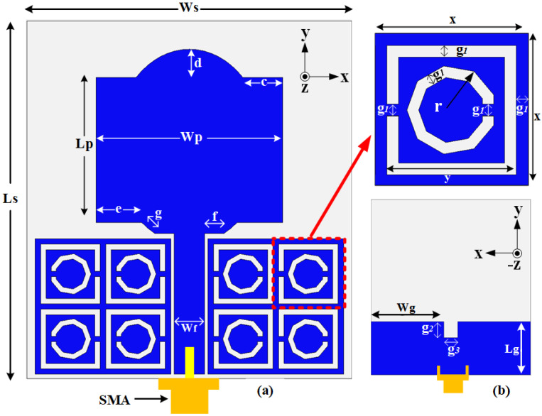
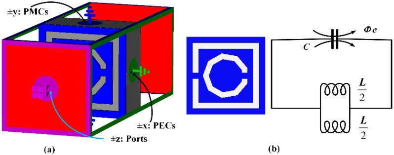
The proposed MTMUCA was designed based on a CSRR structure and is illustrated in Figure 1a. Its overall size was 12.5 × 12.5 × 3 mm3, and other dimensions are summarized in Table 2. A square loop and a nonagonal-shaped structure were combined to form the MTMUC structure. To characterize the metamaterial unit cell, the MTMUC structure was placed between two waveguide ports on the positive and negative z-axis and was excited with a transverse electromagnetic (TEM) wave, as depicted in Figure 2a. It was bounded by a perfect electric conductor (PEC) boundary at the ±x-axis and a perfect magnetic conductor (PMC) boundary at the ±y-axis. A frequency solver with a tetrahedral mesh scheme was utilized in simulations over the frequency of interest. In this metamaterial simulation, the unit cell was without a conductive layer at the bottom [42].
Figure 1.
Schematic diagram of the proposed antenna and the MTMUCA structure (flexible polymer in gray and flexible conductive element in blue): (a) front view; (b) rear view.
Table 2.
Parameter dimensions of the proposed antenna.
| Para. | Value (mm) | Para. | Value (mm) | Para. | Value (mm) |
|---|---|---|---|---|---|
| Ls | 33.00 | c | 3.68 | x | 6.50 |
| Ws | 30.00 | d | 2.60 | y | 5.50 |
| Wp | 17.20 | e | 4.20 | r | 1.75 |
| Lp | 13.40 | f | 1.81 | g2 | 3.00 |
| Wg | 13.70 | g | 1.56 | g3 | 2.60 |
| Lg | 10.00 | g1 | 0.5 | Wf | 2.80 |
Figure 2.
(a) 3D view of the MTMUCA simulation setup. (b) Topology of the MTMUC structure and its equivalent circuit model, where C = capacitance of MTMUCA, L/2 = each inductance (blue indicates the metallized areas).
The MTMUC structure and its equivalent circuit model are depicted in Figure 2b, where ohmic losses are unaccounted for [43]. The MTM modeled on a transverse plane acts as an LC resonator, which can be excited by the orthogonal electric field. Conversely, this structure behaves similarly to an electric dipole when excited by an axial electric field. The primary resonance can also be excited by the external magnetic field along the y-axis, as the CSRR can also exhibit a magnetic behavior [43,44]. The SNG properties can be tailored by appropriately modeling the CSRR gaps into the design. The surface current distribution of the proposed MTM was extracted for further study based on the setup exhibited in Figure 2a.
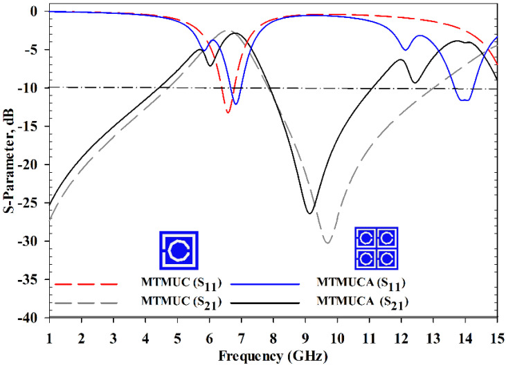
The simulated S-parameter of the MTMs is shown in Figure 3. In prior analyses, the material effective parameters (e.g., permittivity, refractive index) and MTM’s stopband behavior were investigated. The transmission coefficient (S21) of the MTMUC structure ranged from 1 to 4.65 GHz, and from 7.53 to 11.71 GHz, and the reflection coefficient (S11) ranged from 6.34 to 6.68 GHz, and from 13.83 to 14.44 GHz. On the other hand, the MTMUCA showed an operational S21 from 1 to 4.45 GHz, and from 7.84 to 11.18 GHz, whereas the S11 was from 6.34 to 7.01 GHz, and from 13.65 to 14.26 GHz. Hence, the stopband behaviors clearly satisfied the S21 ≤−10 dB requirement.
Figure 3.
S-parameter of the MTMUC and MTMUCA structures.
The RTR [28,45] method was employed to extract the effective parameters from the normal incident scattering parameters using (1) to (7), starting with calculating S11 and S21 from Equations (1) and (2) as follows:
| (1) |
| (2) |
where η is the refractive index, the wave vector in free space is denoted as , the prototype/slab thickness is denoted as d, and . Solving (1) and (2) results in (3) as follows:
| (3) |
| (4) |
where . As the material is deemed to be a passive medium, the impedance imaginary part should be greater than or equal to zero. Additionally, the real part of the refractive index (η) should be greater than or equal to zero. The η value of the material can be obtained from (5):
| (5) |
where m is an integer value or the branch index of the real part of η in other studies [46]. It can be noted that in this extraction method, m = 0 was considered [36]. The values of ε and μ can be determined from the following expression [46,47]:
| (6) |
| (7) |
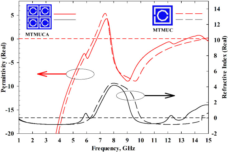
Figure 4 illustrates the real part of the permittivity and refractive index. The MTMUC shows an ENG characteristic (εr < 0) from 1 to 6.45 GHz, from 7.48 to 13.52 GHz, and from 14.96 to 15 GHz, whereas its NZRI characteristic (η < 0) is featured from 1 to 6.16 GHz, and from 9.35 to 13.44 GHz. On the other hand, the MTMUCA displays an ENG characteristic from 1 to 6.75 GHz, from 7.70 to 13.36 GHz, and from 14.73 to 15 GHz, whereas the NZRI characteristic is featured from 1 to 5.74 GHz, 6.21 to 6.37 GHz, 9.48 to 12.08 GHz, and 12.49 to 13.19 GHz. Based on the S-parameters and the MTM characteristics, the proposed MTMUC and MTMUCA can be used for stopband applications and microwave applications [28], e.g., C-band and Ku-band.
Figure 4.
Permittivity and refractive index results of the MTMUC and MTMUCA structures.
2.2. Metamaterial Working Principle
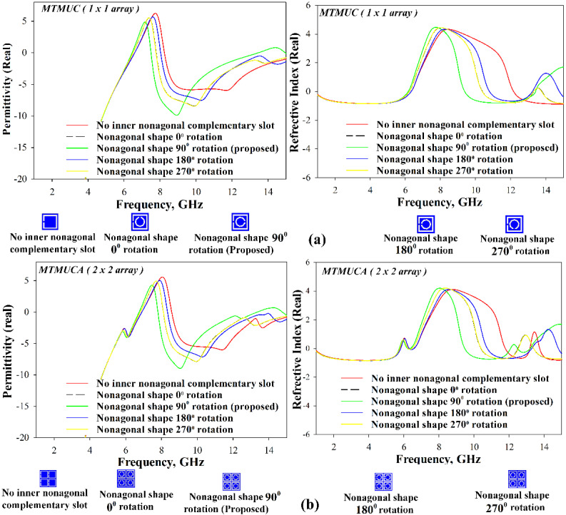
To gain a further understanding of the MTM structure, a parametric study to analyze the effects of the nonagonal-shaped inner split conductor was performed, and its results are presented in Figure 5. In the absence of the inner conductor, a relatively narrower NZRI region can be observed for both the MTMUC and MTMUCA structures. Besides that, the structures’ inner nonagonal-shaped split ring was further evaluated when rotated at 0°, 90°, 180°, and 270° angles. The results are summarized in Table 3. When positioned at 0° and 270° rotation angles, the structure shows identical results for both MTMUC and MTMUCA.
Figure 5.
Analysis of relative permittivity and refractive index of (a) MTMUC and (b) MTMUCA.
Table 3.
Negative permittivity and negative refractive index results of different types of MTM structures.
| MTM Structure | Negative Permittivity Band (GHz) | Negative Refractive Index Band (GHz) | ||
|---|---|---|---|---|
| Array Structure | Inner Nonagonal-Shaped Split Ring Rotation Angle (Degrees) | |||
| 1 × 1 (MTMUC) |


|
– | 1–6.58 8.2–15 |
1–6.33 12.17–15 |
| 0 | 1–6.50 7.78–15 |
1–6.21 10.39–13.33 13.78–15 |
||
| 90 | 1–6.45 7.48–13.52 14.96–15 |
1–6.16 9.35–13.44 |
||
| 180 | 1–6.57 8.02–15 |
1–6.31 10.79–13.26 14.80–15.00 |
||
| 270 | 1–6.50 7.78–15 |
1–6.21 10.39–13.33 13.78–15 |
||
| 2 × 2 (MTMUCA) |


|
– | 1–6.88 8.57–15 |
1–5.79 6.28–6.56 11.79–13.19 13.74–15 |
| 0 | 1–6.80 8.11–15 |
1–5.76 6.23–6.43 10.39–12.5 13.39–15 |
||
| 90 | 1–6.75 7.70–13.36 14.73–15 |
1–5.74 6.21–6.37 9.48–12.08 12.49–13.19 |
||
| 180 | 1–6.88 8.33–15 |
1–5.81 5.56–6.29 10.8–13.28 14.83–15 |
||
| 270 | 1–6.8 8.11–15 |
1–5.76 6.23–6.43 10.39–12.5 13.39–15 |
||
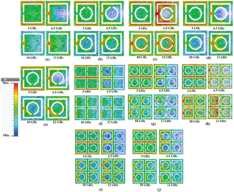
To provide further insight into the working principles and properties of the proposed metamaterial, the simulated current distribution was analyzed and discussed. Figure 6 visualizes the surface current distribution at 3 GHz, 6.5 GHz, 10 GHz, and 12 GHz for the different types of MTM structures. The surface current density and direction are indicated by the colors and arrows, respectively. The concentration of the surface current at 3 GHz is almost indistinguishable, as shown in Figure 6a–e for MTMUC and Figure 6f–j for MTMUCA. On the contrary, when the nonagonal-shaped inner split conductor is absent in Figure 6a,f, a lower surface current density at 6.5 GHz, 10 GHz, and 12 GHz is observed compared to the structures with an inner conductor. Stronger surface currents are also observed at the edges of the rectangles and the nonagonal-shaped slot. For the MTMUC structures (in Figure 6a–e), the concentration of the surface current in Figure 6c shows the strongest surface current distribution. Likewise, among the MTMUCA structures (in Figure 6f–j), Figure 6h indicates the strongest surface current distribution. It is observed that in both cases, the position of the inner nonagonal slot shown in Figure 6c,h facilitated the achievement of stronger surface currents compared to the rest of the structures.
Figure 6.
Surface current distribution for different MTM structures. MTMUC (1×1 array) (a) without the nonagonal-shaped inner split ring, and with (b) 0°, (c) 90°, (d) 180°, and (e) 270° rotation angles of the nonagonal-shaped inner split ring. MTMUCA (2 × 2 array) (f) without the nonagonal-shaped inner split ring, and with (g) 0°, (h) 90°, (i) 180°, and (j) 270° rotation angles of the nonagonal-shaped inner split ring.
Comparison of the structures with different rotation angles indicated that the 90° rotated structure showed the strongest surface current distribution for both MTMUC and MTMUCA. This structure was chosen over the 0° or 270° rotated structure despite the latter being slightly better in terms of ε and NZRI BW. Therefore, the chosen structure was implemented in the UWB antenna to be studied further in the following section.
2.3. Antenna Design Geometry and Configurations
As it has previously been mentioned, the structure of the proposed antenna integrated with the MTMUCA is depicted in Figure 1. The planar monopole antenna was designed with a combination of rectangular and half elliptical-shaped patches, whereas two MTMUCAs were located 0.4 mm from both sides of the planar feedline. A partial ground plane was implemented on the reverse side of this feedline, and a 50 Ω SMA connector was connected at the end of the feedline. The overall dimension of the antenna was 33 × 30 × 3 mm3 (0.825λ0 × 0.75λ0 × 0.075λ0, where λ0 is the free space wavelength at 7.5 GHz, with the MTMUCA sized at 12.5 × 12.5 mm2 (0.312λ0 × 0.312λ0)). All dimensions are summarized in Table 2.
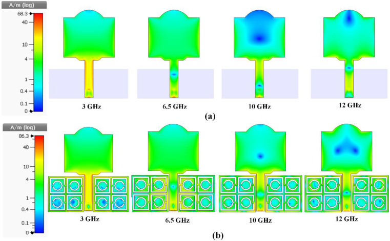
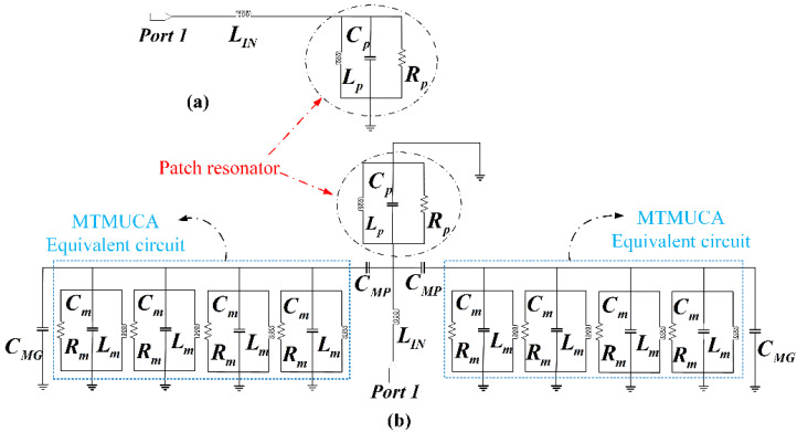
Figure 7 depicts the surface current distribution at 3 GHz, 6.5 GHz, 10 GHz, and 12 GHz with and without the MTMUCA structure integrated into the antenna. It is evident that the MTMUCA improved the current intensity. The circuit model of the structure was modeled based on [44,48,49,50], where the conventional planar monopole antenna model is illustrated in Figure 8a. The planar monopole antenna’s input impedance can be represented as an RLC circuit resonator near its resonance frequency, whereas the microstrip feedline can be expressed as a series inductor [44,48,50], resulting in the overall circuit model shown in Figure 8b. The CSRR-type MTMUC was modeled as a shunt RLC resonator tank (Rm, Lm, and Cm) [44], which was designed to work at the frequencies of interest. The resistor Rm indicates the dielectric and conductor losses, whereas the capacitance and inductance of the MTMCU are denoted as Lm and Cm, respectively. The short distance between the metallic ground plane and the MTMUCA was modeled as a capacitance, expressed as CMG [51], whereas CMP represents the capacitive coupling between the MTMUCA and microstrip feedline and/or patch resonator.
Figure 7.
Surface current distribution. (a) Without the integration of the MTMUCA structure. (b) With the integration of the MTMUCA structure.
Figure 8.
Equivalent circuit model. (a) Conventional planar monopole antenna with microstrip feedline antenna [48,49,50]. (b) Proposed antenna loaded with the MTMUCA demonstrated in Figure 1.
The microstrip feed line behaves as an inductance, denoted as LIN. The CSRR acts as an electric dipole, and it mainly propagates along the xy plane within the substrate and radiates in the vicinity of the antenna.
To be more specific, the metamaterial’s EM energy could be coupled to the planar monopole antenna through CMP, whereas the radiation of the antenna was modeled using the radiation resistance Rp [44]. The same applies to the coupling between the feedline and the MTMUCA. The coupling effect can be seen in Figure 7b, where a significantly increased current concentration is observed. Therefore, the implementation of the MTMUCA enables the operation of the antenna at the frequencies of interest and will be demonstrated in the next section.
3. Results and Discussion
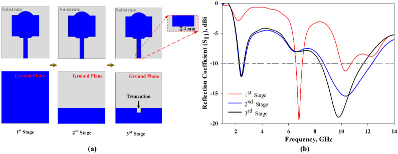
Figure 9 depicts the evolution process of the conventional antenna design in this study. In the first stage, as shown in Figure 9a, a full grounded patch with a combination of rectangular and half elliptical-shaped patches produces relatively narrow frequency bands, as shown in Figure 9b. In order to achieve a wider impedance bandwidth, the ground plane of the antenna was modified, as illustrated in the second stage of Figure 9b. From Figure 9b, it can be seen that the second stage has a wider impedance bandwidth compared to the first stage. Furthermore, in the third stage, a 0.4 mm gap was chosen to avoid a short circuit between the 50 Ω connector and the feedline of the planar monopole antenna. The truncation at the ground plane improved the impedance bandwidth slightly, where S11 resulted in being lower than −10 dB, showing over 2.33–2.6 GHz, and 8.52–12.3 GHz, which means FBW = 47% at the frequencies of interest. It can be noticed that the attained impedance bandwidth does not cover the complete UWB band allocated by the FCC. However, integration of the proposed MTMUCA with the conventional antenna can improve the overall performance. The related evidence can be found in the following results and discussion.
Figure 9.
Evolution process of the conventional antenna in this study. (a) Evolution steps; (b) S11 results.
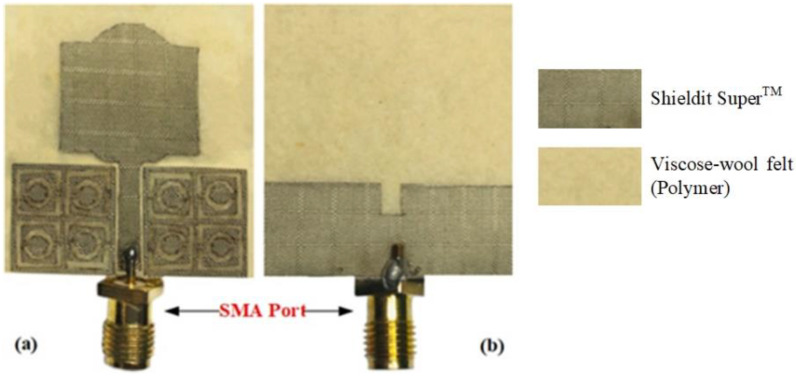
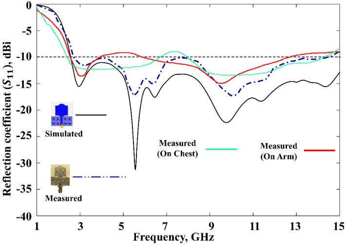
The fabricated prototype was used to validate this work, which is shown in Figure 10. The dielectric polymer material (viscose-wool felt) and conductive material (Shieldit SuperTM) of the prototype were dimensioned by a laser cutting machine as a part of the fabrication process. A great deal of study has already been carried out on a variety of materials that have characteristics that render them appropriate for use as a substrate for conductive materials for antennas, conductive threads [52], conductive polymers [53], and conductive textiles [54]. However, in this study, viscose-wool felt was adopted since it provides easier fabrication with sufficient flexibility and enables strong adhesion with the conductive textile Shieldit SuperTM. S11 measurement was performed using an Agilent E5071C Network Analyser (Agilent Technologies, Bayan Lepas, Penang, Malaysia) to ensure the simulated findings are accurate. The comparison of the proposed antenna between the simulated and measured S11 illustrated in Figure 11 indicates a good agreement. The simulation indicates a 10 dB impedance bandwidth from 2.55 to 15 GHz, which corresponds to an FBW of 142%. The measurement results indicate that this range is from 2.63 to 14.57 GHz, with an FBW of 138.84%. On the other hand, the antenna without the MTMUCA in Figure 9b (third iteration) shows a simulated FBW of 47%. Although the conventional antenna (considering the third iteration in Figure 9) does not work within the FCC region, by utilizing the unique characteristics of the metamaterial, the antenna performance could be enhanced. By utilizing the MTM on the conventional antenna, the antenna element’s radiation efficiency, gain, and overall performance can be improved.
Figure 10.
Prototype of the designed antenna: (a) front view, and (b) rear view.
Figure 11.
Reflection coefficients of the proposed antenna.
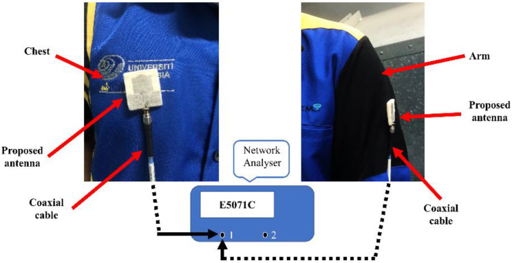
To rigorously analyze the performance of the proposed MTM-driven antenna prototype, body evaluation was further carried out with the help of a male volunteer (with a height of 1.72 m and weight of 84 kg), as shown in Figure 12. The prototype antenna was placed on two different places on the body (chest and arm). The related S11 results are presented in Figure 11, which indicate an excellent performance of the proposed antenna for on-body application. It can be noted that a 6 dB reflection coefficient is frequently used in the manufacturer’s specification, as reported in [55,56]; hence, the obtained performance is sufficient for practical application.
Figure 12.
On-body measurement setup.
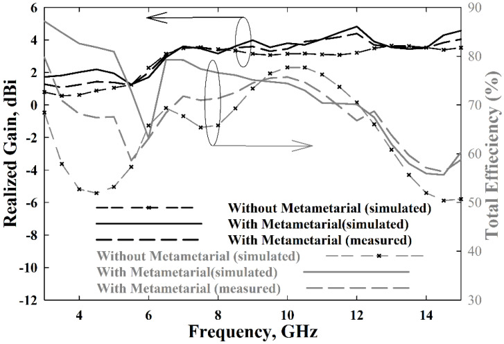
Figure 13 shows the antenna gain and total efficiency over the frequency. In simulations, an average realized gain of 3.3 dBi was achieved with the MTMUCA, whereas it was 2.7 dBi without the MTMUCA. A maximum gain of 4.83 dBi and 3.64 dBi could be obtained with the proposed antenna with and without the MTMUCA, respectively. On the other hand, the average measured gain of the proposed antenna is 3.04 dBi, and the maximum peak gain is 4.4 dBi. The maximum total efficiency achieved is 87% and 79.5% for the antenna with and without MTMUCA implementation, respectively, in simulations. The attainable average total efficiency of the proposed antenna is approximately 73%, whereas the antenna without the MTM indicated levels of around 69%. The measurements show a maximum total efficiency of 80%, and the average efficiency is 68.2%, for the proposed integrated antenna.
Figure 13.
The proposed antenna’s realized gain and radiation efficiency.
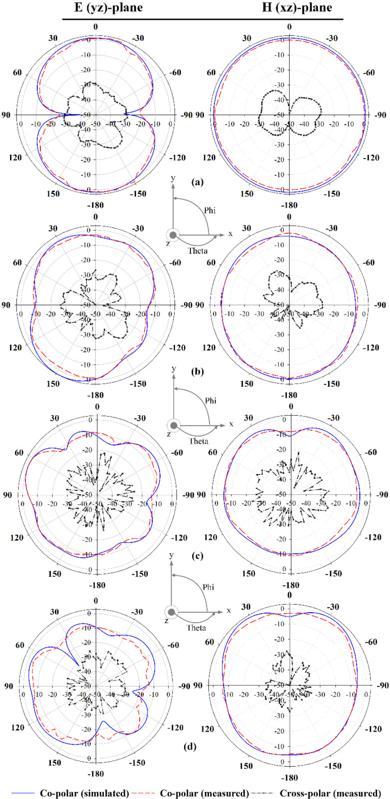
Figure 14 illustrates the radiation characteristics of the proposed antenna. The simulated and measured radiation patterns of the E-plane (yz-plane) and H-plane (xz-plane) were performed at four different frequencies, i.e., 3 GHz, 6.5 GHz, 10 GHz, and 12 GHz, indicating very good agreement. An omnidirectional radiation pattern can be observed at 3 GHz. Meanwhile, at 6.5 GHz, 10 GHz, and 12 GHz, an omnidirectional pattern can be seen in the H-plane, whereas the E-plane shows a bidirectional radiation pattern. Slight discrepancies between the simulations and measurements can be observed due to fabrication inaccuracies.
Figure 14.
Radiation patterns of the proposed antenna at: (a) 3 GHz, (b) 6.5 GHz, (c) 10 GHz, and (d) 12 GHz.
4. Conclusions
A compact textile UWB planar monopole antenna integrated with an MTMUCA featuring ENG and NZRI properties was proposed and studied. The MTM-integrated antenna prototype was fabricated using flexible polymer viscose-wool felt as the substrate (since it provides easier fabrication with sufficient flexibility) and Shieldit SuperTM as the conductive element. The proposed MTMUC structure consists of a unique combination of square- and nonagonal-shaped CSRR-type MTMs. The proposed MTMUCA and MTMUC exhibited SNG properties in different frequency bands. The MTMUCA structure featured an 11.68 GHz ENG bandwidth and an 8.5 GHz NZRI bandwidth. This work also presented an equivalent circuit design to illustrate the principles of the overall structure. The implementation of the MTMUCA into the antenna design was proven experimentally to improve the antenna gain, efficiency, and bandwidth. Measurements showed an FBW of up to 138.84%, from 2.63 to 14.57 GHz, with a peak gain and total efficiency of 4.4 dBi and 80%, respectively. The proposed design can potentially be applied for wearable applications, where future research could be carried out to investigate the feasibility of on-body application, specifically for breast cancer detection.
Author Contributions
Conceptualization, K.H., M.J. and T.S.; design methodology, K.H., M.N.O. and P.J.S.; software, K.H. and H.A.R.; validation, K.H. and T.S.; formal analysis, K.H. and M.N.M.Y.; investigation, K.H.; design optimization, S.S.A.-B.; metamaterial characterization, K.H. and M.N.O.; numerical calculation and data interpretation, M.A.A. and H.A.R.; resources, M.N.O.; writing—original draft preparation, K.H., T.S. and M.J.; writing—review and editing, T.S., P.J.S. and S.S.A.-B.; visualization, K.H. and M.N.M.Y.; supervision, T.S. and M.J.; project administration, M.N.M.Y.; funding acquisition, M.A.A. All authors have read and agreed to the published version of the manuscript.
Funding
This work was supported by the Deanship of Scientific Research at Prince Sattam bin Abdulaziz University, Saudi Arabia.
Institutional Review Board Statement
Not applicable.
Informed Consent Statement
Not applicable.
Data Availability Statement
This study did not report any data.
Conflicts of Interest
The authors declare no conflict of interest.
Footnotes
Publisher’s Note: MDPI stays neutral with regard to jurisdictional claims in published maps and institutional affiliations.
References
- 1.Ali Khan M.U., Raad R., Tubbal F., Theoharis P.I., Liu S., Foroughi J. Bending Analysis of Polymer-Based Flexible Antennas for Wearable, General IoT Applications: A Review. Polymers. 2021;13:357. doi: 10.3390/polym13030357. [DOI] [PMC free article] [PubMed] [Google Scholar]
- 2.Kirtania S.G., Elger A.W., Hasan M.R., Wisniewska A., Sekhar K., Karacolak T., Sekhar P.K. Flexible Antennas: A Review. Micromachines. 2020;11:847. doi: 10.3390/mi11090847. [DOI] [PMC free article] [PubMed] [Google Scholar]
- 3.Farooq S., Tahir A.A., Krewer U., Shah A.U.H.A., Bilal S. Efficient photocatalysis through conductive polymer coated FTO counter electrode in platinum free dye sensitized solar cells. Electrochim. Acta. 2019;320:134544. doi: 10.1016/j.electacta.2019.07.055. [DOI] [Google Scholar]
- 4.Rahman S.U., Bilal S., ul Haq Ali Shah A. Synthesis and Characterization of Polyaniline-Chitosan Patches with Enhanced Stability in Physiological Conditions. Polymers. 2020;12:2870. doi: 10.3390/polym12122870. [DOI] [PMC free article] [PubMed] [Google Scholar]
- 5.Rahman S.U., Röse P., Surati M., Shah A.U.H.A., Krewer U., Bilal S. 3D Polyaniline Nanofibers Anchored on Carbon Paper for High-Performance and Light-Weight Supercapacitors. Polymers. 2020;12:2705. doi: 10.3390/polym12112705. [DOI] [PMC free article] [PubMed] [Google Scholar]
- 6.ur Rahman S., Röse P., ul Haq Ali Shah A., Krewer U., Bilal S. An Amazingly Simple, Fast and Green Synthesis Route to Polyaniline Nanofibers for Efficient Energy Storage. Polymers. 2020;12:2212. doi: 10.3390/polym12102212. [DOI] [PMC free article] [PubMed] [Google Scholar]
- 7.Ur Rahman S., Röse P., ul Haq Ali Shah A., Krewer U., Bilal S., Farooq S. Exploring the Functional Properties of Sodium Phytate Doped Polyaniline Nanofibers Modified FTO Electrodes for High-Performance Binder Free Symmetric Supercapacitors. Polymers. 2021;13:2329. doi: 10.3390/polym13142329. [DOI] [PMC free article] [PubMed] [Google Scholar]
- 8.Bibi S., Ullah H., Ahmad S.M., Ali Shah A.-H., Bilal S., Tahir A.A., Ayub K. Molecular and Electronic Structure Elucidation of Polypyrrole Gas Sensors. J. Phys. Chem. C. 2015;119:15994–16003. doi: 10.1021/acs.jpcc.5b03242. [DOI] [Google Scholar]
- 9.Zia T.U.H., Ali Shah A.U.H. Understanding the adsorption of 1 NLB antibody on polyaniline nanotubes as a function of zeta potential and surface charge density for detection of hepatitis C core antigen: A label-free impedimetric immunosensor. Colloids Surfaces A Physicochem. Eng. Asp. 2021;626:127076. doi: 10.1016/j.colsurfa.2021.127076. [DOI] [Google Scholar]
- 10.Jiang X., Xu C., Gao T., Bando Y., Golberg D., Dai P., Hu M., Ma R., Hu Z., Wang X.-B. Flexible conductive polymer composite materials based on strutted graphene foam. Compos. Commun. 2021;25:100757. doi: 10.1016/j.coco.2021.100757. [DOI] [Google Scholar]
- 11.Zhou K., Dai K., Liu C., Shen C. Flexible conductive polymer composites for smart wearable strain sensors. SmartMat. 2020;1:1–5. doi: 10.1002/smm2.1010. [DOI] [Google Scholar]
- 12.Mohamadzade B., Hashmi R.M., Simorangkir R.B.V.B., Gharaei R., Ur Rehman S., Abbasi Q.H. Recent Advances in Fabrication Methods for Flexible Antennas in Wearable Devices: State of the Art. Sensors. 2019;19:2312. doi: 10.3390/s19102312. [DOI] [PMC free article] [PubMed] [Google Scholar]
- 13.Jamshaid H., Mishra R., Zeeshan M., Zahid B., Basra S.A., Tichy M., Muller M. Mechanical Performance of Knitted Hollow Composites from Recycled Cotton and Glass Fibers for Packaging Applications. Polymers. 2021;13:2381. doi: 10.3390/polym13142381. [DOI] [PMC free article] [PubMed] [Google Scholar]
- 14.Commission F.C. FCC Report and Order for Part 15 Acceptance of Ultra Wideband (UWB) Systems from 3.1–10.6 GHz. FCC; Washington, DC, USA: 2002. pp. 1–10. [Google Scholar]
- 15.Samal P.B., Soh P.J., Zakaria Z. Compact Microstrip-Based Textile Antenna for 802.15.6 WBAN-UWB with Full Ground Plane. Int. J. Antennas Propag. 2019;2019:1–12. doi: 10.1155/2019/8283236. [DOI] [Google Scholar]
- 16.Samal P.B., Soh P.J., Xu H., Vandenbosch G.A.E. Microstrip-based all-textile unidirectional UWB antenna with full ground plane; Proceedings of the 8th European Conference on Antennas and Propagation, EuCAP 2014; Hague, The Netherlands. 6–11 April 2014; pp. 1408–1412. [DOI] [Google Scholar]
- 17.Yalduz H., Koç B., Kuzu L., Turkmen M. An ultra-wide band low-SAR flexible metasurface-enabled antenna for WBAN applications. Appl. Phys. A Mater. Sci. Process. 2019;125:1–11. doi: 10.1007/s00339-019-2902-4. [DOI] [Google Scholar]
- 18.Gao G.P., Hu B., Wang S.F., Yang C. Wearable Circular Ring Slot Antenna with EBG Structure for Wireless Body Area Network. IEEE Antennas Wirel. Propag. Lett. 2018;17:434–437. doi: 10.1109/LAWP.2018.2794061. [DOI] [Google Scholar]
- 19.Tian X., Lee P.M., Tan Y.J., Wu T.L.Y., Yao H., Zhang M., Li Z., Ng K.A., Tee B.C.K., Ho J.S. Wireless body sensor networks based on metamaterial textiles. Nat. Electron. 2019;2:243–251. doi: 10.1038/s41928-019-0257-7. [DOI] [Google Scholar]
- 20.Moradi B., Fernández-García R., Gil I. E-Textile Embroidered Metamaterial Transmission Line for Signal Propagation Control. Materials. 2018;11:955. doi: 10.3390/ma11060955. [DOI] [PMC free article] [PubMed] [Google Scholar]
- 21.Zhang K., Soh P.J., Yan S. Meta-Wearable Antennas—A Review of Metamaterial Based Antennas in Wireless Body Area Networks. Materials. 2020;14:149. doi: 10.3390/ma14010149. [DOI] [PMC free article] [PubMed] [Google Scholar]
- 22.Wu J.F., Qiu C., Wang Y., Zhao R., Cai Z.P., Zhao X.G., He S.S., Wang F., Wang Q., Li J.Q. Human limb motion detection with novel flexible capacitive angle sensor based on conductive textile. Electronics. 2018;7:192. doi: 10.3390/electronics7090192. [DOI] [Google Scholar]
- 23.Tartare G., Zeng X., Koehl L. Development of a wearable system for monitoring the firefighter’s physiological state; Proceedings of the 2018 IEEE Industrial Cyber-Physical Systems ICPS 2018; St. Petersburg, Russia. 15–18 May 2018; pp. 561–566. [DOI] [Google Scholar]
- 24.Saenz-Cogollo J.F., Pau M., Fraboni B., Bonfiglio A. Pressure mapping mat for tele-home care applications. Sensors. 2016;16:365. doi: 10.3390/s16030365. [DOI] [PMC free article] [PubMed] [Google Scholar]
- 25.Gric T., Hess O. Metamaterial Cloaking. In: Gric T., Hess O., editors. Phenomena of Optical Metamaterials. Elsevier; Amsterdam, The Netherlands: 2019. pp. 175–186. [Google Scholar]
- 26.Ahdi Rezaeieh S., Antoniades M.A., Abbosh A.M. Gain Enhancement of Wideband Metamaterial-Loaded Loop Antenna with Tightly Coupled Arc-Shaped Directors. IEEE Trans. Antennas Propag. 2017;65:2090–2095. doi: 10.1109/TAP.2017.2671027. [DOI] [Google Scholar]
- 27.Islam M.M.T., Islam M.M.T., Samsuzzaman M., Faruque M.R.I. Compact metamaterial antenna for UWB applications. Electron. Lett. 2015;51:1222–1224. doi: 10.1049/el.2015.2131. [DOI] [Google Scholar]
- 28.Al-Bawri S.S., Hwang Goh H., Islam M.S., Wong H.Y., Jamlos M.F., Narbudowiczm A., Jusoh M., Sabapathy T., Khan R., Islam M.T. Compact Ultra-Wideband Monopole Antenna Loaded with Metamaterial. Sensors. 2020;20:796. doi: 10.3390/s20030796. [DOI] [PMC free article] [PubMed] [Google Scholar]
- 29.Khandelwal M.K., Arora A., Kumar S., Kim K.W., Choi H.C. Dual band double negative (DNG) metamaterial with small frequency ratio. J. Electromagn. Waves Appl. 2018;32:2167–2181. doi: 10.1080/09205071.2018.1498026. [DOI] [Google Scholar]
- 30.Singh H., Sohi B.S., Gupta A. A compact CRLH metamaterial with wide band negative index characteristics. Bull. Mater. Sci. 2019;42:1–11. doi: 10.1007/s12034-019-1861-x. [DOI] [Google Scholar]
- 31.Islam S.S., Iqbal Faruque M.R., Islam M.T. Design and absorption analysis of a new multiband split-S-shaped metamaterial. Sci. Eng. Compos. Mater. 2017;24:139–148. doi: 10.1515/secm-2014-0376. [DOI] [Google Scholar]
- 32.Hossain K., Sabapathy T., Jusoh M., Soh P.J., Osman M.N., Al-Bawri S.S. A Compact Wideband CSRR Near Zero Refractive Index and Epsilon Negative Metamaterial for Wearable Microwave Applications. J. Phys. Conf. Ser. 2021;1962:012019. doi: 10.1088/1742-6596/1962/1/012019. [DOI] [Google Scholar]
- 33.Alemaryeen A., Noghanian S. Crumpling effects and specific absorption rates of flexible AMC integrated antennas. IET Microw. Antennas Propag. 2018;12:627–635. doi: 10.1049/iet-map.2017.0652. [DOI] [Google Scholar]
- 34.Mersani A., Osman L., Ribero J.M. Flexible UWB AMC antenna for early stage skin cancer identification. Prog. Electromagn. Res. M. 2019;80:71–81. doi: 10.2528/PIERM18121404. [DOI] [Google Scholar]
- 35.Islam M.M., Islam M.T., Faruque M.R.I., Samsuzzaman M., Misran N., Arshad H. Microwave imaging sensor using compact metamaterial UWB antenna with a high correlation factor. Materials. 2015;8:4631–4651. doi: 10.3390/ma8084631. [DOI] [PMC free article] [PubMed] [Google Scholar]
- 36.Hossain K., Sabapathy T., Jusoh M., Soh P.J., Jamaluddin M.H., Al-Bawri S.S., Osman M.N., Ahmad R.B., Rahim H.A., Mohd Yasin M.N., et al. Electrically Tunable Left-Handed Textile Metamaterial for Microwave Applications. Materials. 2021;14:1274. doi: 10.3390/ma14051274. [DOI] [PMC free article] [PubMed] [Google Scholar]
- 37.Wang F., Arslan T. A wearable ultra-wideband monopole antenna with flexible artificial magnetic conductor; Proceedings of the 2016 Loughborough Antennas & Propagation Conference LAPC 2016; Loughborough, UK. 14–15 November 2016; pp. 3–7. [DOI] [Google Scholar]
- 38.Gogikar S., Chilukuri S. A Compact Wearable Textile Antenna with Dual Band-Notched Characteristics for UWB Applications; Proceedings of the 2019 9th IEEE-APS Topical Conference on Antennas and Propagation in Wireless Communications APWC 2019; Granada, Spain. 9–13 September 2019; pp. 426–430. [DOI] [Google Scholar]
- 39.Elwi T.A. Novel UWB printed metamaterial microstrip antenna based organic substrates for RF-energy harvesting applications. AEU Int. J. Electron. Commun. 2019;101:44–53. doi: 10.1016/j.aeue.2019.01.026. [DOI] [Google Scholar]
- 40.Negi D., Khanna R., Kaur J. Design and performance analysis of a conformal CPW fed wideband antenna with Mu-Negative metamaterial for wearable applications. Int. J. Microw. Wirel. Technol. 2019;11:806–820. doi: 10.1017/S1759078719000497. [DOI] [Google Scholar]
- 41.Sabapathy T., Soh P.J., Jusoh M. A Three-Year Improvement Assessment of Project-Based Learning for an Antennas and Propagation Course [Education Corner] IEEE Antennas Propag. Mag. 2020;62:76–84. doi: 10.1109/MAP.2020.3027264. [DOI] [Google Scholar]
- 42.Hossain T.M., Jamlos M.A.F., Jamlos M.A.F., Soh P.J., Islam M.I., Khan R. Modified H-shaped DNG metamaterial for multiband microwave application. Appl. Phys. A Mater. Sci. Process. 2018;124:183. doi: 10.1007/s00339-018-1593-6. [DOI] [Google Scholar]
- 43.Baena J.D., Bonache J., Martín F., Sillero R.M., Falcone F., Lopetegi T., Laso M.A.G., García-García J., Gil I., Portillo M.F., et al. Equivalent-circuit models for split-ring resonators and complementary split-ring resonators coupled to planar transmission lines. IEEE Trans. Microw. Theory Tech. 2005;53:1451–1460. doi: 10.1109/TMTT.2005.845211. [DOI] [Google Scholar]
- 44.Dong Y., Toyao H., Itoh T. Design and characterization of miniaturized patch antennas loaded with complementary split-ring resonators. IEEE Trans. Antennas Propag. 2012;60:772–785. doi: 10.1109/TAP.2011.2173120. [DOI] [Google Scholar]
- 45.Chen X., Grzegorczyk T.M., Wu B.I., Pacheco J., Kong J.A. Robust method to retrieve the constitutive effective parameters of metamaterials. Phys. Rev. E Stat. Physics Plasmas Fluids Relat. Interdiscip. Top. 2004;70:7. doi: 10.1103/PhysRevE.70.016608. [DOI] [PubMed] [Google Scholar]
- 46.Islam S.S., Faruque M.R.I., Islam M.T. A new direct retrieval method of refractive index for the metamaterial. Curr. Sci. 2015;109:337–342. [Google Scholar]
- 47.Hossain K., Sabapathy T., Jusoh M., Soh P.J., Fazilah A.F.M., Halim A.A.A., Raghava N.S., Podilchak S.K., Schreurs D., Abbasi Q.H. ENG and NZRI Characteristics of Decagonal-Shaped Metamaterial for Wearable Applications; Proceedings of the 2020 International Conference on UK-China Emerging Technologies (UCET); Glasgow, UK. 20–21 August 2020; pp. 1–4. [Google Scholar]
- 48.Moradikordalivand A., Rahman T.A., Ebrahimi S., Hakimi S. An equivalent circuit model for broadband modified rectangular microstrip-fed monopole antenna. Wirel. Pers. Commun. 2014;77:1363–1375. doi: 10.1007/s11277-013-1585-y. [DOI] [Google Scholar]
- 49.Wang Y., Li J.Z., Ran L.X. An equivalent circuit modeling method for ultra-wideband antennas. Prog. Electromagn. Res. 2008;82:433–445. doi: 10.2528/PIER08032303. [DOI] [Google Scholar]
- 50.Balanis C.A. Antenna Theory: Analysis and Design. John Wiley & Sons; 2016. [Google Scholar]
- 51.Navarro-Cía M., Beruete M., Agrafiotis S., Falcone F., Sorolla M., Maier S.A. Broadband spoof plasmons and subwavelength electromagnetic energy confinement on ultrathin metafilms. Opt. Express. 2009;17:18184. doi: 10.1364/OE.17.018184. [DOI] [PubMed] [Google Scholar]
- 52.Huang X., Leng T., Zhang X., Chen J.C., Chang K.H., Geim A.K., Novoselov K.S., Hu Z. Binder-free highly conductive graphene laminate for low cost printed radio frequency applications. Appl. Phys. Lett. 2015;106:203105. doi: 10.1063/1.4919935. [DOI] [Google Scholar]
- 53.Sayem A.S.M., Simorangkir R.B.V.B., Esselle K.P., Hashmi R.M. Development of Robust Transparent Conformal Antennas Based on Conductive Mesh-Polymer Composite for Unobtrusive Wearable Applications. IEEE Trans. Antennas Propag. 2019;67:7216–7224. doi: 10.1109/TAP.2019.2930116. [DOI] [Google Scholar]
- 54.Corchia L., Monti G., Tarricone L. Durability of Wearable Antennas Based on Nonwoven Conductive Fabrics: Experimental Study on Resistance to Washing and Ironing. Int. J. Antennas Propag. 2018;2018:1–8. doi: 10.1155/2018/2340293. [DOI] [Google Scholar]
- 55.Guo Z., Tian H., Wang X., Luo Q., Ji Y. Bandwidth enhancement of monopole uwb antenna with new slots and ebg structures. IEEE Antennas Wirel. Propag. Lett. 2013;12:1550–1553. doi: 10.1109/LAWP.2013.2292063. [DOI] [Google Scholar]
- 56.Bialkowski M.E., Razali A.R., Boldaji A. Design of an ultrawideband monopole antenna for portable radio transceiver. IEEE Antennas Wirel. Propag. Lett. 2010;9:554–557. doi: 10.1109/LAWP.2010.2052230. [DOI] [Google Scholar]
Associated Data
This section collects any data citations, data availability statements, or supplementary materials included in this article.
Data Availability Statement
This study did not report any data.


