Abstract
Tight integration of CMUT arrays with integrated circuits can make active impedance matching feasible for practical imaging devices. In this paper, negative capacitance-based impedance matching for CMUTs is investigated. Simple equivalent circuit model based calculations show the potential of negative capacitance matching for improving the bandwidth along with electrical power transfer and acoustic reflectivity, but the model has limitations especially for acoustic reflectivity evaluation. For more realistic results, an experimentally validated CMUT array model is applied to a small 1-D CMUT array operating in the 5–15MHz range. The results highlight the difference between electrical power transfer and acoustic reflectivity as well as the tradeoffs in SNR. According to the results, ideal negative capacitance termination matched to the CMUT capacitance provides the broadest bandwidth and highest SNR if acoustic or electrical reflections are of no concern. On the other hand, negative capacitance and resistance matching to minimize acoustic reflectivity provides both lower reflection and closer to ideal SNR as compared to electrical power matching. It is observed that acoustic matching also reduces acoustic crosstalk and improves array uniformity. While several challenges for integrated circuit implementation are present, negative capacitance-based impedance matching can be a viable broadband active impedance matching method for CMUTs operating in conventional and collapsed mode as well as other ultrasound transducers with mainly capacitive impedance.
Index Terms—: Capacitive micromachined ultrasonic transducer (CMUT), negative capacitance, broadband impedance matching, acoustic reflectivity, electrical power transfer
I. INTRODUCTION
One of the main advantages of capacitive micromachined ultrasonic transducers (CMUTs) is ease of electronic integration, which can be achieved through wafer bonding, monolithic post-CMOS processing, or flip-chip bonding methods [1]–[10]. This integration capability enables implementation of 2-D imaging arrays with small element sizes and high impedance values to achieve high SNR and bandwidth, along with multiplexing capabilities for reduced number of cables for catheter-based applications [11]–[13]. In these implementations, a significant, but not fully utilized advantage of electronics integration is the capability to implement different impedance matching schemes for CMUT elements, including active matching circuits. This is important, as the electrical impedance levels of CMUTs are generally higher than their piezoelectric counterparts, typical voltage-based or current-based frontend terminations using low-noise amplifier structures increase the electrical and acoustic reflection from CMUT arrays due to mismatched impedance levels.
There has been a few studies on improvements in terms of power transfer and acoustic reflection for CMUTs in the literature [14], [15]. Impedance matching of CMUT using a resistance only load has been explored in detail including the impact of backing on acoustic reflectivity [15]. It is found that assuming a real acoustic radiation impedance for the CMUT and limiting the termination to an optimized resistance, significant reduction in acoustic reflectivity and increased sensitivity can be obtained when CMUT elements are biased closed to the collapse voltage. Inductive tuning, which seems like a straightforward approach for a capacitive transducer, has not been considered for practical reasons.
An interesting approach to impedance matching for CMUTs that suitable for integrated circuit implementation is to cancel the capacitive part of the CMUT impedance using a negative capacitance circuit [16]. These active circuits are commonly used to cancel parasitic capacitance and broaden the system bandwidth [17]. This approach has been suggested to minimize acoustic reflection over a broad frequency range for CMUTs, and has been demonstrated using discrete components, but a detailed analysis is not provided [14]. In that study, as well as others [15], electrical power transfer is not differentiated from acoustic reflectivity, and a real radiation impedance is assumed for the CMUT. Although minimum acoustic reflectivity is highly desirable, it may not occur along with the condition for maximum power transfer from the transducer: The former happens when acoustic impedance matching is achieved between medium and the CMUT surface [18] while the latter is obtained under complex conjugate electrical impedance matching (maximum power transfer impedance matching) at the interface of the CMUT and front-end electronics (electrical port) [19]. As noted below, this difference can be important for small sized transducers and array elements where simple 1-D equivalent circuit analysis is not suitable.
In this paper, a detailed analysis of CMUT arrays with an impedance matching network is performed with a focus on negative capacitance based matching. First, the small signal lumped equivalent circuit calculations are presented to provide insight into the bandwidth, sensitivity, and SNR with different matching schemes. Calculations of electrical and acoustic reflectivity for small and large area CMUTs highlight the differences between the two figures and the need for more complex array models. Based on those results, an experimentally verified accurate model is used to evaluate the impact of terminations on single element and a small CMUT array, and the results are compared with the equivalent circuit approach. Different aspects of the negative capacitance matching and its realization using integrated circuits are discussed followed by concluding remarks.
II. Impedance Matching Metrics and Analysis Methods
A. Figures of merit for impedance matching
Impedance matching in ultrasonic transducers is generally used for two different purposes: maximum power transfer from acoustic to electrical domain and minimizing acoustic reflections from the surface of the array. Given the complex electrical input impedance of the CMUT array element, loaded with fluid and including interactions with other array elements, ZCMUT(ω), the frequency dependent electrical power reflection coefficient at the electrical interface as a function of frequency [20] is given as:
| (1) |
where * denotes complex conjugate and Zin(ω) is the input impedance of the receiver electronics. As expected from the maximum power transfer theorem, power reflection is minimized by complex conjugate matching in the electrical domain. Note that this figure is relatively straightforward to calculate once ZCMUT is known, as all electromechanical interactions in CMUT are properly included in a single complex number. Consequently, for a limited and relevant bandwidth of the CMUT array element (from ω1 to ω2) one can define an effective power reflection coefficient,
| (2) |
To highlight the difference between the acoustic and electrical reflection coefficient, one can consider the acoustic pressure reflection coefficient at the mechanical interface of a transducer and radiation medium, similar to a 1-D plane wave reflection coefficient,
| (3) |
where Zina(ω) is the complex mechanical impedance seen looking into the mechanical port of the CMUT and Zrad(ω) is the complex radiation impedance of the medium including array effects [21]-[23]. Note that unlike the electrical power reflection coefficient, minimum acoustic reflectivity does not require complex conjugate matching and difference becomes significant when the radiation impedance is complex [24].
Equation (3) is convenient to use with a simple 1-D equivalent circuit and provides accurate insight for large area transducers. However, for realistic CMUT array elements with arbitrary or sub-wavelength dimensions, a more complex coupled electrical-acoustic model considering membrane and array dynamics should be used. The acoustic reflectivity can then be evaluated through electrical signals due to multiple reflections (echoes) between an ideal flat target and the CMUT array. In that case one can define an effective acoustic reflection coefficient at the CMUT array surface as:
| (4) |
where |V1(ω)|, |V2(ω)|, are the electrical signals in frequency domain for the first and second echoes, respectively, obtained at the receiver electronics terminals. Then, similar to the effective electrical power reflection, ERE, one can define an effective acoustic reflection coefficient, ERA, over a frequency band of interest as:
| (5) |
Another important metric for receiver performance is the achievable signal to noise ratio (SNR). This figure is calculated from the ratio of the output signal voltage to the voltage noise on the termination impedance due to the CMUT element and termination impedance. These figures can be calculated as a function of frequency and integrated over a bandwidth to arrive an effective SNR for different termination schemes indicated in Fig. 1.
Fig. 1.
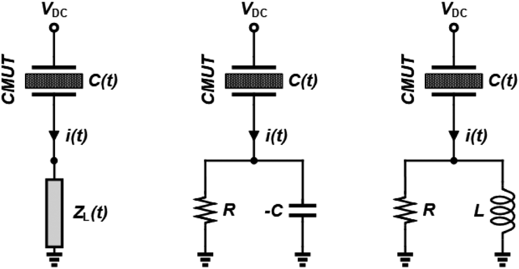
Circuit model for a CMUT element, in which the CMUT element is a linear time varying capacitor terminated by a load impedance. Also shown are the −C//R and L//R matching topologies.
B. Equivalent Circuit Based Analysis
Conventional small signal equivalent circuit for a CMUT [25] with a parallel negative capacitance termination (−C//RL), is shown in Fig. 2. Here, n=VDCC0/g is the electromechanical transformation ratio, in which VDC is the applied DC bias, C0 is the CMUT capacitance, and g is the gap between CMUT plates with the bias. The −C0 element represents the spring softening due to the electromechanical coupling with applied bias [26]. The force Fin is given by the blocked pressure and device area, i.e. Fin = 2Pin × A. Given this equivalent circuit, the reflectivity at the mechanical (acoustic) port can be found from (3) as
| (6.1) |
where
| (6.2) |
and the power reflection coefficient defined in [20] for the electrical power transfer to the load, RL, is given by
| (7) |
where ZCMUT, Matching is the input electrical impedance of the CMUT including the negative capacitance, and * denotes the complex conjugate.
Fig. 2.

Mason’s small signal equivalent circuit for a capacitive micromachined ultrasonic transducer (CMUT) in receive mode. Zrad and Zmem are the total impedances which are the normalized impedances multiplied by effective area.
To estimate the impact of parallel negative capacitance, one can first assume a limiting case where Zrad is real (such as Zrad = A × ρc, for a large transducer), C is chosen to be arbitrarily close to C0 so that the . By defining a short circuit mechanical impedance , [27] at the softened (short circuit) mechanical resonance frequency of the CMUT, (Zms=0) both acoustic and electrical power reflection coefficients vanish by choosing indicating a perfect match. The bandwidth of this matching depends on the variation of the membrane mechanical impedance with frequency and its relative value as compared to Zrad as the output voltage is given by
| (8) |
Since CMUT membrane mechanical impedance is usually designed to be significantly smaller than the radiation impedance, giving the CMUT its broad bandwidth, one should expect (−C//R) matching to provide a broadband matching and output voltage frequency response limited by the membrane design. This is in contrast with (L//R) matching, where the capacitance is cancelled only around a narrow frequency band. As will be discussed later, although this approach seems to reduce the output signal level as compared to an open circuit termination by voltage division, (−C//R) matching eliminates the capacitive drop off and can yield higher output signal levels in a broader frequency range.
For arbitrary sized transducers, frequencies and negative capacitance values, one can choose load resistance values to minimize the expressions in (6) and (7) to reduce the acoustic reflectivity and increase electrical power transfer at a desired frequency, respectively. This yields
| (9) |
for electrical power transfer. The resistance value for minimizing acoustic reflectivity can be obtained by evaluating the expression in (6.1), since a closed form expression is not trivial. As in the case of microwave circuits [28] these values are not the same, as Zrad is complex and Zms is non-zero in general, and they depend on CMUT size and membrane design.
In addition to output signal levels for different terminations, the equivalent circuit can also be used to evaluate the noise voltage spectrum due to the thermal mechanical noise of the CMUT and the load resistance, through the expression
| (10) |
where Zin_e(ω) is the electrical input impedance at the output terminal including the load resistance. Note that this approach assumes noiseless receiver electronics and hence is an ideal case. Nevertheless, to gain insight into these matching schemes on signal bandwidth, SNR and reflectivity, one can use the equivalent circuit approach, albeit with its limitations.
C. Equivalent Circuit Analysis Results
The equivalent circuit analysis is used to evaluate performance metrics for two square-shaped 5-MHz single-element CMUTs. As detailed in Table I, SE_CMUT1 has side length of 161 μm and SE_CMUT2 has side length of 659 μm, roughly corresponding to λ/2 and 2λ at 5MHz respectively in the simulation medium, which is water. These sizes are chosen to explore the limitations of the equivalent circuit approach leading to the need for more accurate analysis. The membranes are modeled as lossless mass-spring systems , where membrane equivalent mass and stiffness and collapse voltage are obtained using the FEA and BEM analysis [29] and the radiation impedance is calculated for square apertures as described in [30].
TABLE I.
SINGLE ELEMENT CMUTS AND 1-D CMUT ARRAY ELEMENT PROPERTIES
| Parameter | SE_CMUT1 | SE_CMUT2 | CMUT Array |
|---|---|---|---|
| No. of Membranes | 4 | 64 | 80 (per element) |
| Membrane Size | 78 × 78 μm2 | 78 × 78 μm2 | 46 × 46 μm2 |
| Electrode Area Coverage | 59% | 59% | 68% |
| Membrane Spacing | 5 μm | 5 μm | 6 μm |
| Membrane Thickness | 1.5 μm | 1.5 μm | 2.2 μm |
| Vacuum Gap | 125 nm | 125 nm | 95 nm |
| Dielectric Relative Permittivity | 15 | 15 | 6.3 |
| SixNy Isolation Thickness | 40 nm | 40 nm | 200 nm |
| Collapse Voltage | 14 V | 14 V | 40 V |
Fig. 3 shows the variation of |RA(ω)| and |RE(ω)| at 5 MHz for C=0.99C0 and C=0.95C0 for SE_CMUT1 (top) and SE_CMUT2 (bottom). As seen in the C=0.99C0 curves for SE_CMUT1, the load resistance for minimizing acoustic reflectivity (RL = 520 kΩ) and electrical power reflectivity are significantly different, and power reflection is minimized at RL = 767 kΩ as predicted by (9). As expected, the minima are reduced with improved matching with the CMUT capacitance. This match is limited to 99% as exact match would cause stability issues in practical implementation. More importantly, it is seen that acoustic reflectivity is larger than unity at certain resistance values which is not physical, while electrical reflectivity is always below unity, indicating the limitation of this simple 1-D equivalent circuit formulation for the acoustic reflectivity analysis of small sized transducers. Calculations for SE_CMUT2 show that the optimal resistances are closer to each other (RL = 33.5 kΩ for acoustic and RL = 35.5 kΩ for electrical power) as expected from the above analysis and the validity of the 1-D acoustic reflectivity improves with increasing transducer size. Note that in this large transducer case the imaginary part of the electrical impedance is due to C0, and hence one can extract RL for best electrical match from a parallel RC model fitting.
Fig. 3.
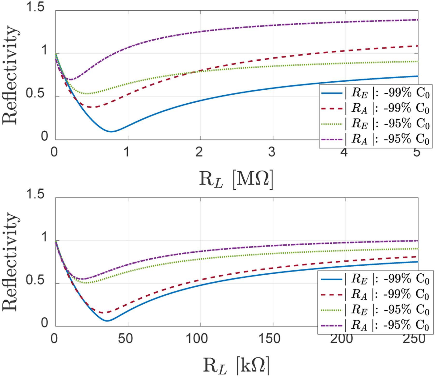
Reflectivity magnitude as a function of the termination resistance for (−C//R) termination for SE_CMUT1 (C0 = 1.72 pF, TOP) and for SE_CMUT2 (C0=27.56 pF, BOTTOM).
To illustrate the broad bandwidth of (−C//R) matching approach as compared to (L//R) matching, |RA(ω)| and |RE(ω)| are evaluated as a function of frequency for the optimal electrical load resistance value for SE_CMUT2 for these two different matching schemes. Fig. 4 shows the main advantage of negative capacitance-based matching: significantly higher bandwidth as compared to inductive matching. It is also observed that acoustic reflectivity formulation breaks down at low frequencies where the effective CMUT size is deep subwavelength, indicating the need for a different approach for realistic cases.
Fig. 4.
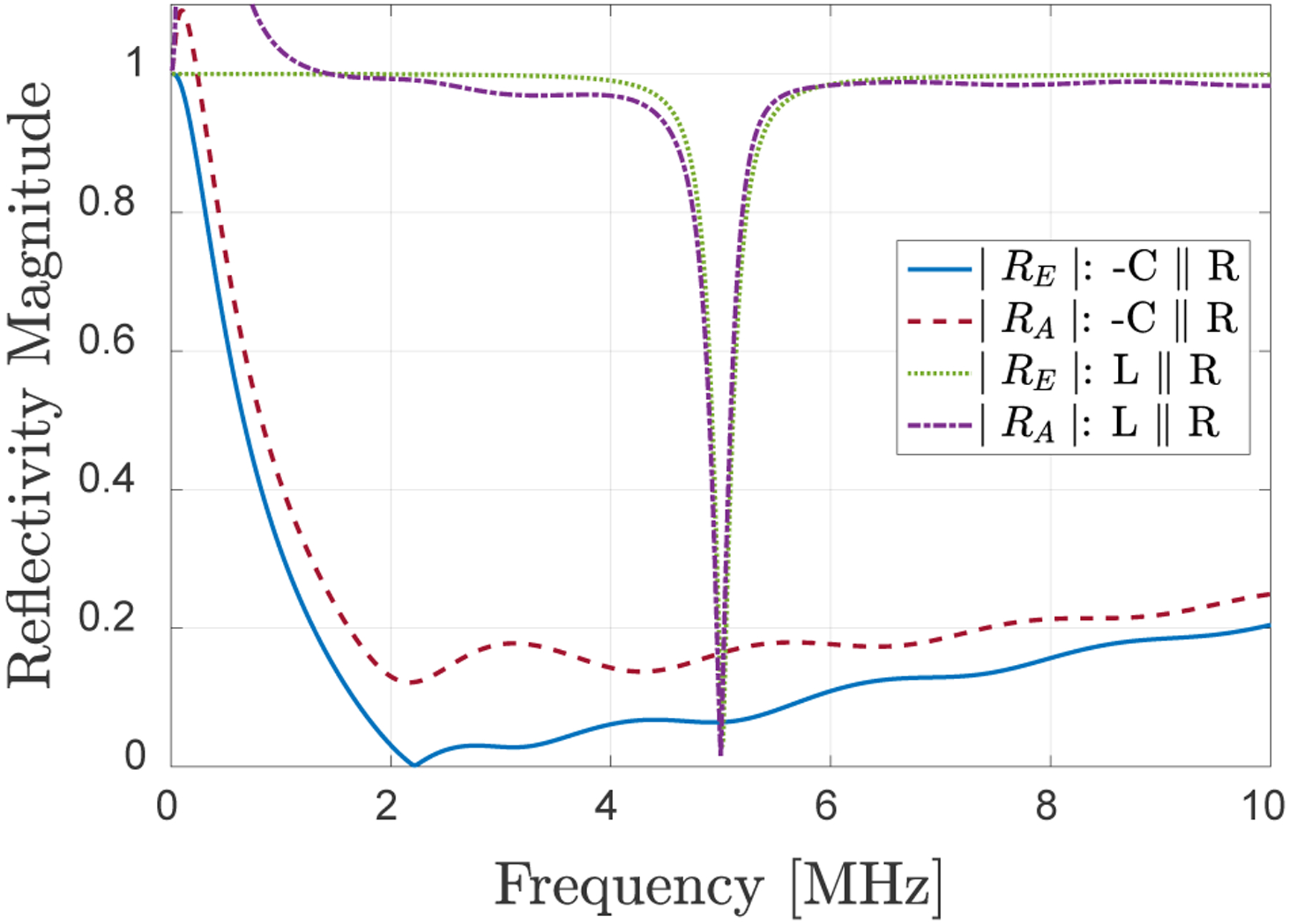
SE_CMUT 2 reflectivity magnitude as a function of frequency for different matching schemes. Capacitance and resistance are optimized for minimum electrical power reflection.
Impact of different matching schemes on the output signal and achievable SNR levels is also investigated on the SE_CMUT2 example to provide further insight. In addition to (−C//R) and (L//R) matching, the case of only −C matching, i.e. −C in parallel with 1GΩ (−C), and 1GΩ (OC-open circuit) conditions are also included for comparison. Fig. 5 shows that with an open circuit termination such as the case of a voltage amplifier, negative capacitance provides a nearly flat output response as it removes the impact of the reduction in impedance due to the CMUT capacitance and parasitic capacitance. This is a well-known use of negative capacitance circuits for bandwidth enhancement and equalization [16]. Note that in this case high bandwidth is achieved with high acoustic and electrical reflectivity. With (−C//R) matching, the broad bandwidth is retained with ~5 dB lower output signal, but the acoustic and electrical reflectivity are significantly reduced as seen in Fig. 4. Interestingly, the voltage sensitivity is significantly (>20 dB) higher than the open circuit termination in the bandwidth of interest. Therefore, (−C//R) termination can provide higher sensitivity (output signal) and bandwidth as compared to a typical high impedance voltage amplifier termination. Finally, as expected, (L//R) matching has a narrowband response.
Fig. 5.
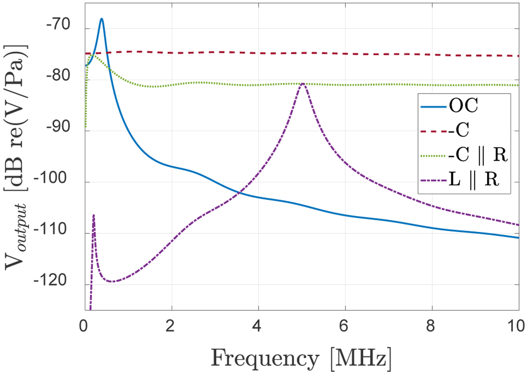
SE_CMUT2 output voltage signal for different terminations.
Corresponding noise voltage calculations, which take the CMUT thermal mechanical noise and the noise due to the termination resistance into account, are shown in Fig. 6. The results indicate that with (−C//R) and (L//R) terminations there is about 3 dB degradation in the SNR as compared to open circuit or −C type terminations. This points to a trade-off between reduced reflectivity and SNR. However, in many cases the noise in the system is not limited by the CMUT and termination impedance noise but by other noise sources such as transmit receive switch resistance and amplifier noise [31]. In those cases where the dynamic range is limited by these other noise sources, the significant increase in signal level and bandwidth achieved with (−C//R) matching (Fig. 5) can increase the overall SNR and dynamic range, even with the additional noise due to the active circuitry. As noted later, this is a subject for further research.
Fig. 6.
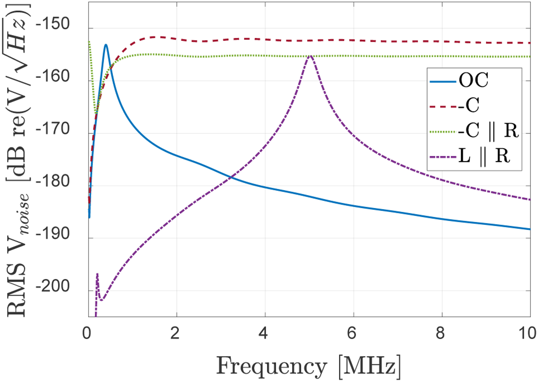
SE_CMUT2 output voltage noise spectrum for different terminations.
D. Coupled Time Domain Model Based Analysis
Although the simple equivalent circuit analysis provides guidance for negative capacitance matching optimization, it does not consider the complex CMUT membrane and array dynamics with acoustic interactions. Higher order membrane vibration modes, which are significant in determining the CMUT performance and bandwidth are also not considered [32]. Furthermore, evaluation of acoustic reflectivity using a 1-D model is not adequate for smaller sized CMUT array elements as discussed above, pointing to the need for an approach such as in (4) to evaluate RAE(ω). Therefore, for a more realistic and comprehensive analysis, an experimentally verified SIMULINK based CMUT array model is used [33]. In this time domain model receive mode voltage and current are expressed by
| (11) |
where Ƒ−1 is the inverse Fourier transform, V(t) is the voltage across variable capacitor C(t), a time-varying capacitor in electrical domain, i(t) is the output current of the variable capacitor, and ZT, is the termination impedance including the matching circuit and the load. These load and matching circuit impedances as well as any parasitic capacitance can be included in the model directly or as finite impulse response (FIR) filters. For the case of an ideal −C//R matching, the method could be further simplified by separating the termination impedance and matching circuit to obtain output voltage and current as:
| (12) |
In the model, the CMUT array element impedance, can be extracted by simulating the output current to a Gaussian input voltage pulse in short-circuit termination to be used for noise calculations as well as obtaining the RC model parameters [32].
E. Coupled Time Domain Model Results
For comparison with the equivalent circuit results, SE_CMUT2 is simulated using the time domain model to extract the impedance and RC model fit in the frequency band of 2.5 to 7.5 MHz. This results in R=55 kΩ at 5 MHz (different from the simple equivalent circuit), which is used to determine the element values for the L//R and −C//R matching circuits. Figure 7 shows the electrical power reflection coefficient as a function of frequency for different terminations including OC (1 GΩ) and −C (−20.57 pF//600 kΩ) cases. Note that the resistance value for −C termination are limited to smaller values as compared to OC case, due to the numerical instabilities observed while simulating cases with high −C and R values. As compared to Fig. 4, the L//R matching result is similar with a narrowband matching and OC and −C matching results in unity reflection. The −C//R termination provides low power reflection over a significantly broader bandwidth, but as compared to the equivalent circuit based results, crosstalk effects are seen at low frequencies and the bandwidth at the high frequency end is limited by higher order membrane vibration modes. The effective electrical reflection, ERE, calculated using (2) over the 2.5–7.5 MHz bandwidth is obtained to be 92.96% for L//R, and 18.75% for −C//R matching.
Fig. 7.
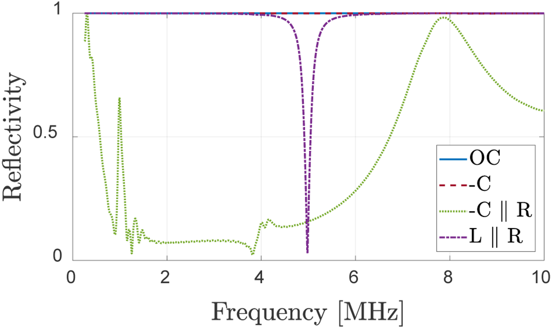
Comparison of electrical power reflection coefficient for OC, −C, L//R and −C//R terminations calculated using the coupled time domain analysis.
To obtain the acoustic reflectivity RAE(ω) using (5), the transient simulation capability of the model is utilized. The CMUT element is excited with a short pulse and multiple time domain echo signals from a perfect planar reflector at a certain distance (in this case 7.5 mm) are simulated as shown in Fig. 8(a). The ratios of the second to first echo spectra [Fig. 8(b)] in dB over the frequency range of interest are used to compare the ERA of different receiver electrical terminations. In this particular case, the signals and RAE(ω) are shown for the optimized case of ERA with R=90 kΩ. The acoustic reflectivity curves are similar for all cases except for −C//R case which reduces the reflectivity over a broad range in the targeted bandwidth. In contrast with the equivalent circuit model, the resistance for −C//R matching minimizing ERA is larger than the value minimizing ERE. Also, unlike the electrical power reflection, in a realistic case the acoustic reflection RA will not be totally eliminated at any frequency as the space between the CMUT membranes and the area outside the array are modeled as a rigid baffle. Furthermore, the improvements in RA are relative since the individual echo levels depend on diffraction, i.e. the distance between the CMUT array and the planar reflector, in addition to the CMUT array acoustic impedance, leading to a plot in dBs. Nevertheless, this metric can be used to investigate and minimize acoustic reflectivity of the CMUT array by comparing it for different terminations.
Fig. 8.
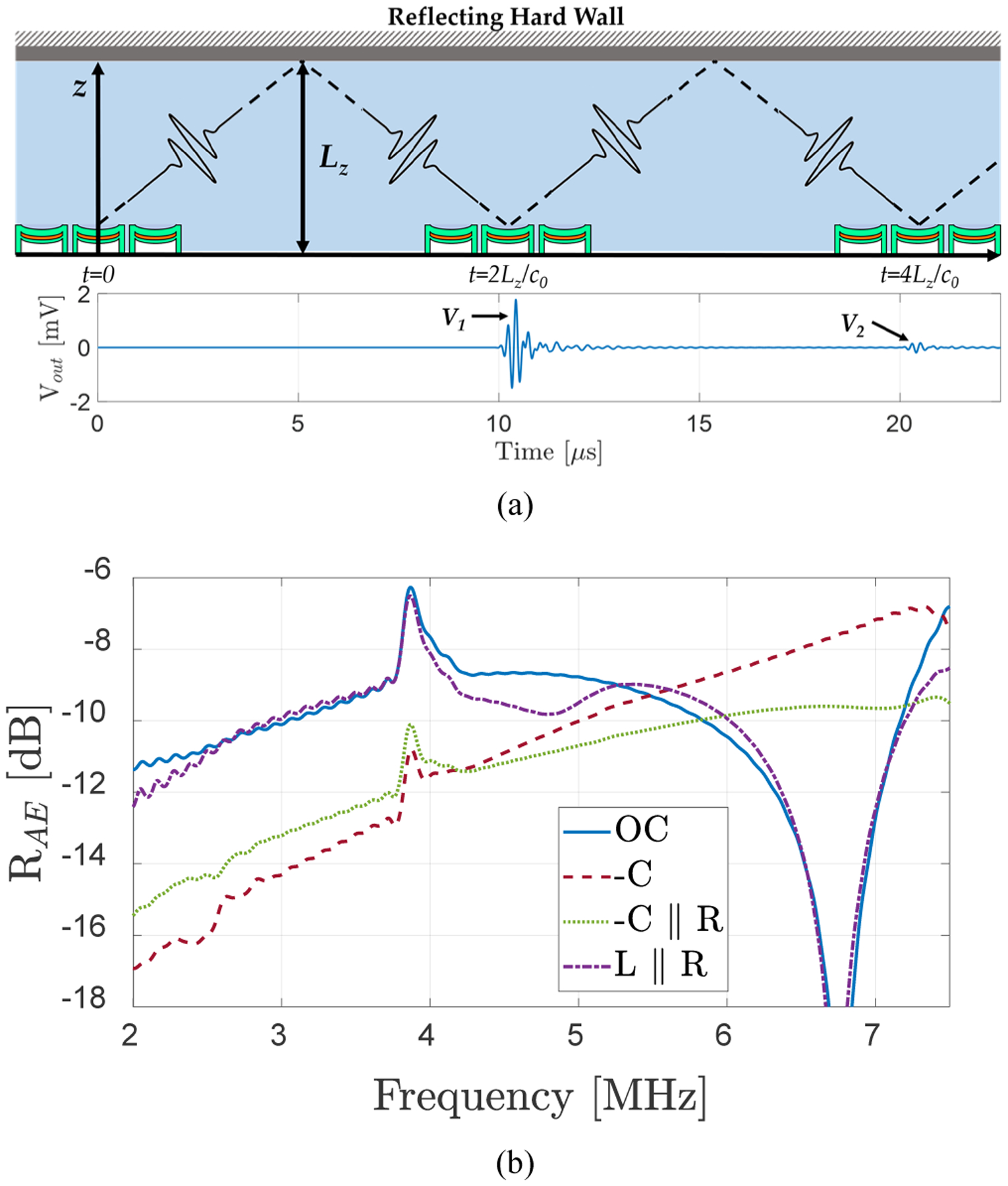
(a) Pulse-echo voltage signals obtained at the SE_CMUT2 receiver electronic terminals as a function of time for effective acoustic reflection coefficient calculation. (b) Effective acoustic reflection coefficient from Eqns. 4 and 5 for different terminations.
III. Application to a CMUT Array
CMUT imaging arrays are usually formed by subwavelength elements with large number of membranes. Therefore, based on the preceding results, impact of negative capacitance-based impedance matching on bandwidth, acoustic reflection, and possible SNR for an array of CMUT elements is best analyzed using the time domain model. A small 1-D CMUT array designed to operate in a frequency range suitable for intracardiac echocardiography (ICE) imaging is used as an example. The properties of the array operating at a center frequency (f0) of 9 MHz and demonstrating 65% fractional bandwidth (FBW) are listed in Table I [34]. The 3-element array as shown in Fig. 9 is not large, but nevertheless with 240 individual membranes it shows the dominant acoustic crosstalk effects and thus deemed suitable to interpret the impact of electrical matching on array crosstalk and to perform a parametric study for ERE and ERA optimization. The array element impedance is approximated as an (16 kΩ // 7.38 pF) for a DC bias of 90% collapse at 36V bias, where the capacitance value is the static capacitance, Co, at this bias. To obtain the time domain voltage signals, pulse echo signals from the center and side elements are obtained by exciting the center element with a 50-ns-width 36-V unipolar pulse.
Fig. 9.

1-D CMUT array geometry used in the array analysis. Each element is 2 membranes wide and 40 membranes long. Center (light) and edge elements (darker) are denoted with different shading.
Fig. 10 shows the first and second echo signals at the terminals of the center and edge elements for a perfect reflector 1 cm away from the array for OC (1GΩ), −C (−7.01 pF ∥500 kΩ), L//R (45 μH ∥16 kΩ), and −C//R (−7.31 pF ∥105 kΩ) terminations. These values correspond to perfect complex conjugate matching for L//R matching at 9 MHz and optimum negative capacitance acoustic matching. Also included in the graphs are zoomed in version of the second echo signals for ease of comparison. Negative capacitance (−C) termination provides the maximum amplitude for the first echo signal, and (−C//R) termination generates larger output signal as compared to the OC case. Maximum reduction in echo amplitude from first to the second echo is obtained in (−C//R) case, as expected, indicating the improvement in acoustic reflectivity. In addition, the ringing in the echo signals is minimized indicating a broader bandwidth. This is clearly seen in Fig. 11, where the frequency spectrums for the first echo signals for the center and edge elements are plotted. These trends are in line with the general predictions of the 1-D equivalent circuit model, but there are significant differences and additional information provided by the coupled time domain model. Negative capacitance (−C) termination provides nearly flat frequency response, but it also enhances a higher order membrane mode around 15 MHz, which causes the ringing in Fig. 10(b). Similar to SE_CMUT2 case, the resistance value for optimum acoustic matching is significantly larger than the resistance for optimum electrical power transfer. Importantly, this model provides information on the array behavior. Proper broadband matching termination affects the CMUT array response such that the array elements show similar responses with negligible mismatch in frequency components of their spectra [Fig. 10(d)]. Comparison of the curves shows that the difference between edge and center elements is smallest for (−C//R) matching. The uniformity of the of the CMUT array response is improved as the acoustic crosstalk effects are reduced when the array absorbs most of the incident acoustic energy, an important advantage of broadband acoustic matching.
Fig. 10.
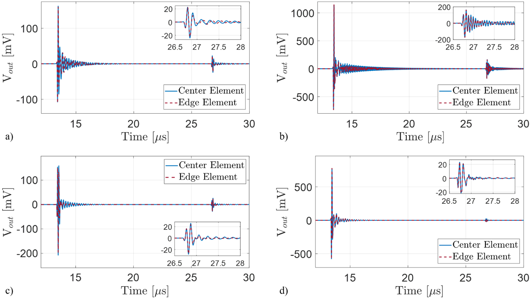
Simulated CMUT responses for different receiver terminations employing the pulse-echo model (the plane reflector is placed 1 cm away from the CMUT: (a) Open-circuit (1 GΩ) termination; (b) −C termination (−7.01 pF ∥500 kΩ); (c) Narrowband matching circuit with parallel L and R (45 μH ∥16 kΩ) termination. The resistor value is based on complex conjugate matching at the electrical port; (d) Broadband matching circuit with parallel −C and R (−7.31 pF ∥ 105 kΩ) termination. The resistor value is based on minimum acoustic reflectivity.
Fig. 11.
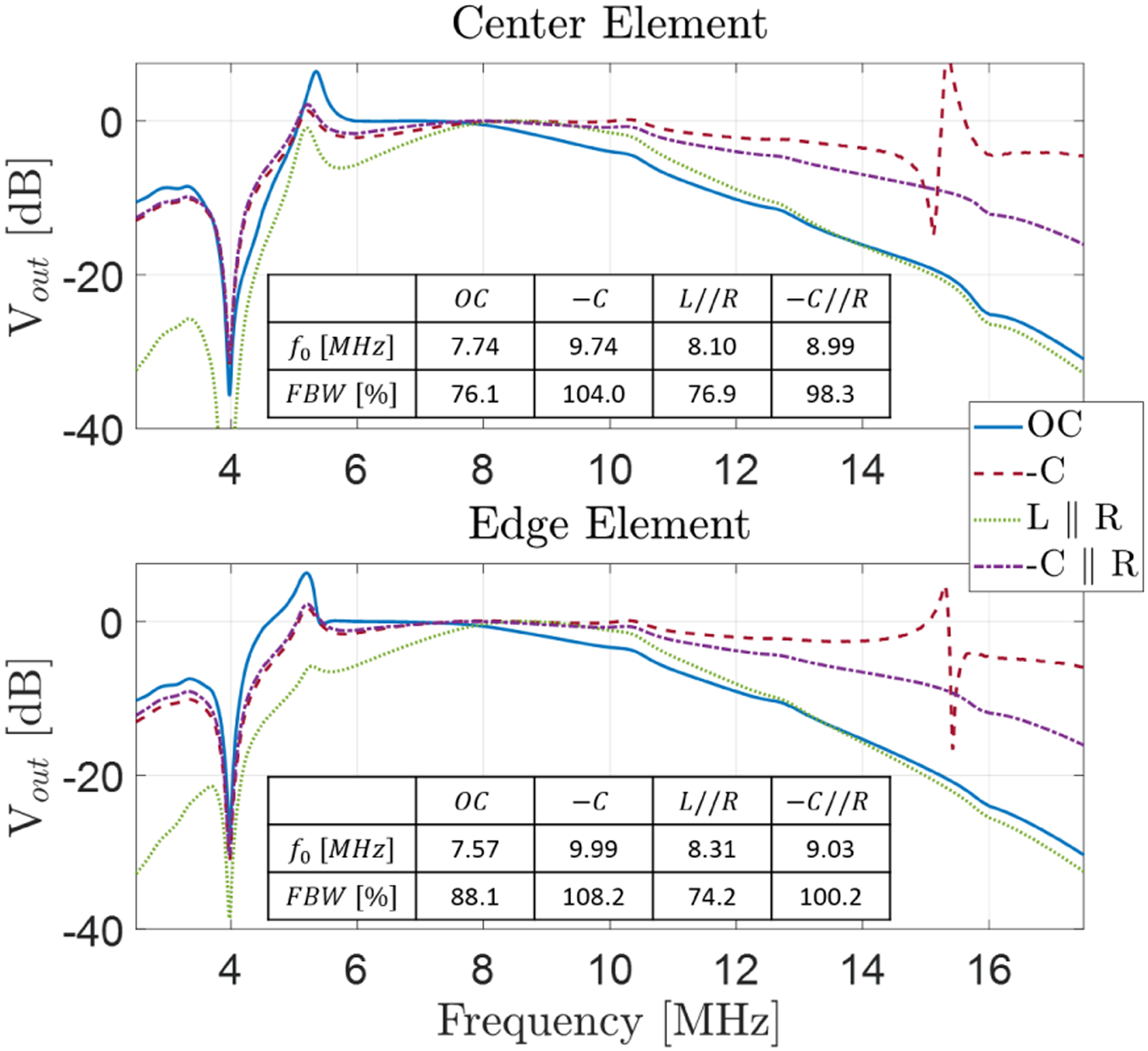
Normalized frequency spectrums of the echo signals for different terminations for the center (top) and edge (bottom) element of the CMUT array. Broadband negative capacitance matching provides the broadest fractional bandwidth and smallest difference between the center and edge elements.
To further emphasize the reduction in scattered pressure from the CMUT array elements, Fig 12. shows the acoustic pressure echo signals at the CMUT surface. The first pressure pulse is the same for all receiver terminations since during the transmit pulse the CMUT is connected to the same pulser. The impact of receiver termination is seen during the second pressure pulse as it gets reflected from the CMUT array and radiates back toward the medium. The inset focused on the second pressure pulse clearly indicates that −C//R termination significantly reduces the scattered pressure.
Fig. 12.
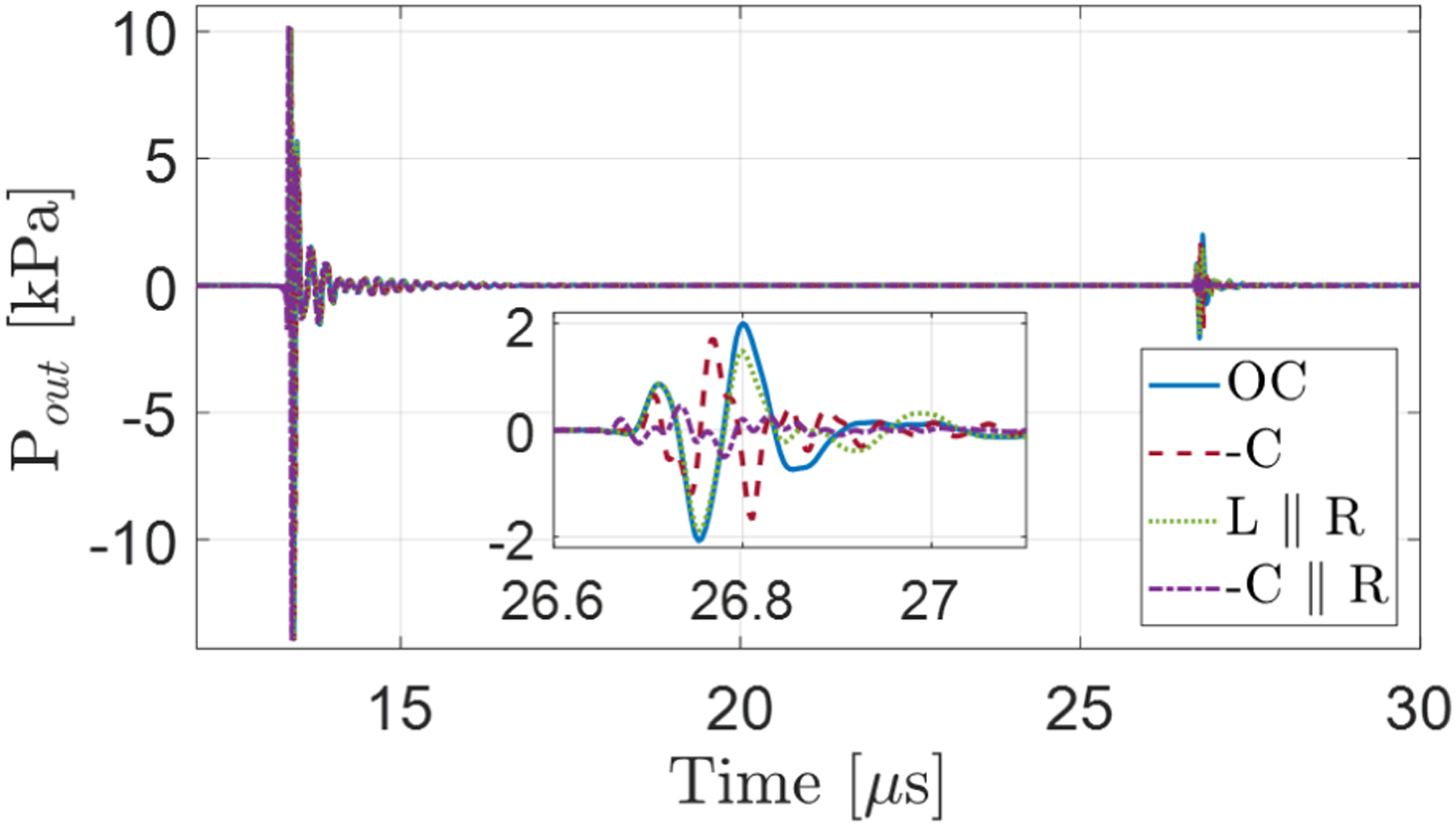
Simulated pulse-echo output acoustic pressure of the CMUT at 2 cm distance with different terminations (the plane reflector is placed at 1 cm distance from the CMUT). The broadband matching by negative capacitance significantly decreases the reflected output pressure.
To observe overall trends and tradeoffs between electrical, acoustic matching and SNR for different matching schemes, effective electrical power reflectivity (ERE) and effective acoustic reflectivity (ERA) in the 5–15 MHz range are calculated for the CMUT array as a function of load resistance and negative capacitance. Fig. 13 includes these results as well as the −C and L//R matching cases as single points for comparison. Note that the resistance only matching case corresponds to the case discussed in [15], therefore this graph provides a comprehensive comparison for different termination schemes. Negative capacitance impedance matching improves the ERE and reaches a minimum at R=16–19 kΩ with less than −8 dB when the magnitude of C is over 0.9Co, as expected from conjugate impedance matching.
Fig. 13.
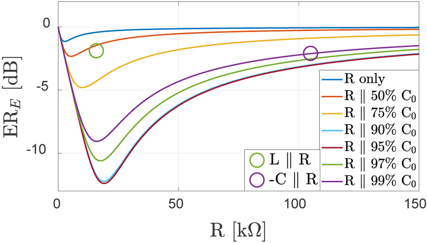
Variation of ERE with varying parallel resistance for different terminations, including resistance only matching. Negating the CMUT capacitance provides better power transfer with maximum power transfer over the 5–15 MHz bandwidth. The points corresponding to optimal L//R and minimum acoustic reflectivity are also shown.
When ERA (normalized to the OC case) is evaluated for similar resistance and capacitance cases, as shown in Fig. 14, it is seen that −C//R matching shows improvement over purely resistive or L//R matching after C=0.9Co. An important point to note is that the resistance value minimizing acoustic reflectivity is 105 kΩ, which is significantly larger from the value for minimum ERE. This is in contrast with the equivalent circuit model and justifies the need for accurate modeling.
Fig. 14.
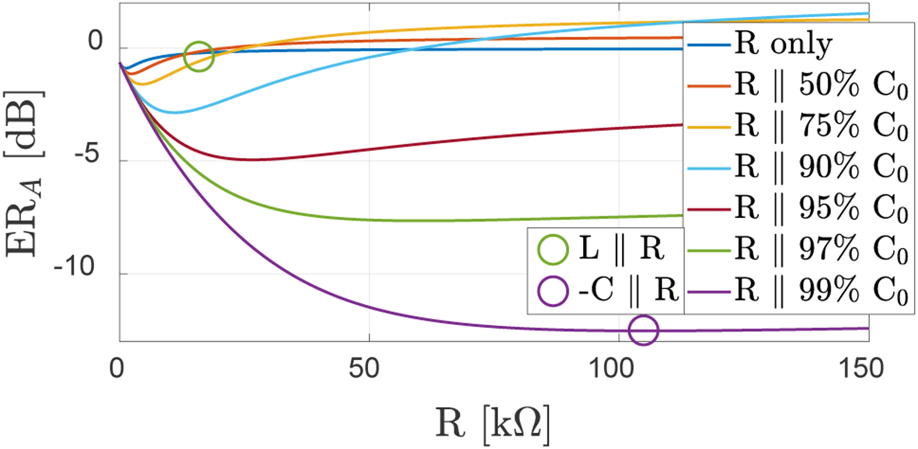
Variation of ERA with varying parallel resistance for different terminations, including resistance only matching. Negating the CMUT capacitance provide better acoustic reflectivity and the minimum ERA is achieved in a different −C//R value as compared to the resistive load for maximum power transfer.
To see the impact of −C//R matching on the overall achievable SNR, this figure is evaluated as a function of termination resistance and several C values. To calculate the SNR, total RMS noise is obtained by integrating the power spectral density (PSD) of the noise voltage, as calculated in (10), over the bandwidth of interest (5–15 MHz), and the peak value of the first echo signal is chosen as the signal level. Fig. 15 shows the SNR variation as well as the SNR achieved by −C and OC termination cases. Minimum ERE and ERA cases are also indicated. As in the case of equivalent circuit analysis, ideal OC and −C terminations provide higher SNR. The case of −C termination here seems to provide higher SNR which may be due to its impact on the acoustic crosstalk, hence the CMUT impedance. In any case, with this voltage amplifier detection scheme, there is a tradeoff between SNR and acoustic or electrical matching. If there is no concern with electrical or acoustic matching, −C matching will provide both larger bandwidth and SNR. Similarly, with R only matching, larger resistances will improve SNR. Since increasing load resistance improves the SNR one should minimize acoustic reflectivity rather than increasing electrical power transfer for better potential SNR. As a result, it is possible to achieve SNR close to the ideal OC case while providing higher bandwidth and low acoustic reflectivity.
Fig. 15.
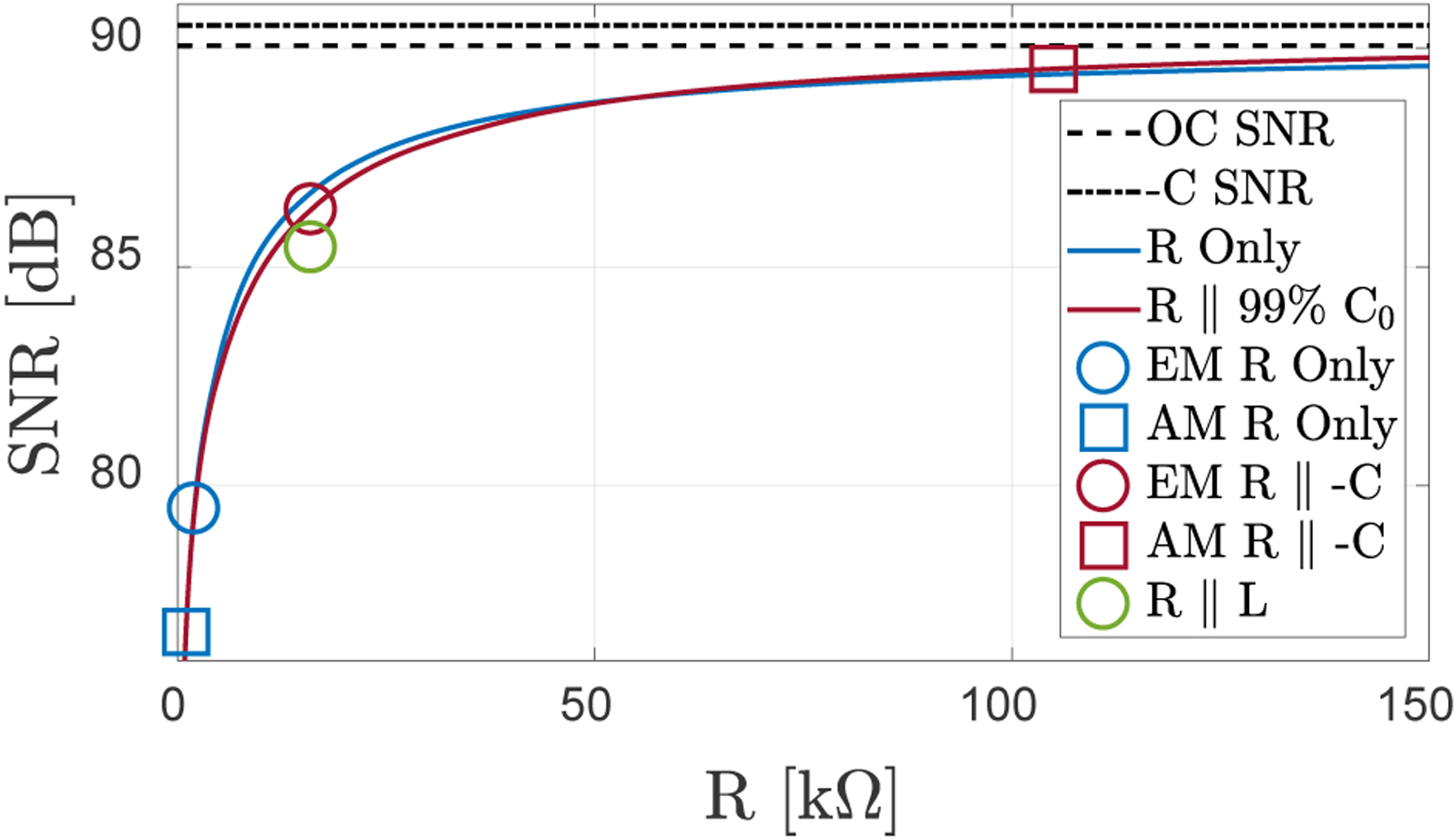
Calculated SNR for different terminations. EM and AM designations indicate the optimal conditions for electrical power and acoustic matching conditions, respectively, for the corresponding matching approach.
IV. Discussion
The simple equivalent circuit analysis shows that by closely matching the CMUT capacitance with a negative capacitance, the bandwidth of the receiver can be significantly improved as high frequency roll off due to device and parasitic capacitance can be prevented. This approach has been used in electrical circuits for the same purpose. With large area CMUTs, choosing the resistance according to the formula given in (9), both the electrical and acoustic reflectivity can be improved with a small degradation in SNR. A more accurate model considering the higher order membrane modes and array effect confirms the general trend for bandwidth, but it provides information on limits of bandwidth improvement. It indicates that load resistance for minimum acoustic reflectivity is larger than required for maximum electrical power transfer.
Importantly, the coupled model shows that with reduced acoustic reflectivity in a broad bandwidth, the non-uniformity of the CMUT array is reduced. This is probably due to less acoustic energy scattered from the array reducing the crosstalk, resulting in less energy traveling along the surface of the array and reflecting from the edges. Therefore, negative capacitance based broadband impedance matching can improve the imaging performance of the CMUT arrays by not only reducing the clutter due to undesired echoes, but also with more ideal array behavior over a larger bandwidth.
Overall, the analysis suggests that once an R//C model is obtained for the CMUT in the bandwidth of interest, using a circuit generating negative capacitance close to −C value and a load resistance larger than R will provide a good compromise with SNR, bandwidth, and acoustic reflectivity. Cancelling transducer capacitance in a broadband impedance matching approach is likely to be useful for other types of transducers such as bulk piezoelectric transducers and piezoelectric micromachined ultrasonic transducers (PMUTs) whose characteristic is dominated by a capacitive response. In fact, negative capacitance-based controllers with piezoelectric actuators have already been suggested for broadband vibration suppression [35], [36].
While the analysis here is performed for non-collapsed mode CMUT, it is applicable to collapsed mode CMUTs as the overall impedance [37], [38] and acoustic crosstalk behavior are similar [39]. The active circuitry providing negative capacitance can be tunable to accommodate the large capacitance changes with the DC bias in the collapsed mode operation [40], [41]. As seen in Figs. 13 and 14, tunability would be important as performance of negative impedance matching can change significantly over a small range of capacitance.
A limitation of the present analysis in terms of acoustics is the perfectly rigid and infinite baffle condition. The impact of a more realistic baffle can be analyzed using coupled FEA as done for the case of CMUT with backing in [15].
In terms of electronics, the main compromise with negative capacitance-based impedance matching is the need for additional active circuits which increases complexity, power consumption, and noise level. Integrated circuit topologies suitable for this purpose include a transconductance-based impedance converter as mentioned in [42]. These circuits basically use a positive feedback to make a negative capacitance from a unit capacitor, and a capacitive or resistive ratio increases or decreases the impedance magnitude [43]-[45]. However, circuits using a positive feedback topology raises the possibility of feedback control loop instability; therefore, this issue needs to be further considered.
Although it is clear that negative capacitance circuitry improves the bandwidth of the system, its impact on overall system SNR will depend on the dominant noise sources. For CMUT thermal noise limited detectors [7], [46], [47] (as represented the OC condition here), added circuits may decrease the SNR, whereas in cases where noise due to other sources such as transmit-receive switches are significant, the system SNR can be improved along with the bandwidth. Note that CMUT output current detection methods assuming ideal short circuits are not considered here as cancelling CMUT capacitance does not have an impact in that case. However, realistic TIA implementations have finite input impedance and can be modified with negative capacitance matching. These issues related to practical integrated circuit implementation will be investigated in detail in future studies.
V. Conclusion
A comprehensive analysis of impedance matching for CMUT array elements shows that negative capacitance-based impedance matching provides improved performance in a broad bandwidth in terms of electrical power transfer, acoustic reflectivity with a compromise in SNR as compared to thermal noise limited case. When a CMUT array is analyzed with complex membrane and array dynamics, optimum impedance condition for maximum power transfer do not coincide with the minimum acoustic reflectivity condition. While negative capacitance and a high resistance provides high SNR and bandwidth, it suffers from high acoustic and electrical reflection. Targeting minimum acoustic reflectivity provides a better SNR-bandwidth tradeoff as compared to minimizing electrical reflection. Simulations on CMUT array behavior also indicate that the uniformity of the CMUT array improves with broadband impedance matching as the undesired membrane vibrations are damped. Noting that negative capacitance-based matching can be tunable, it can especially be useful for collapsed mode CMUTs where capacitance and frequency response changes significantly with DC bias. The trade-off between the increased front-end electronics complexity, power consumption and system SNR needs to be further analyzed for practical implementations.
ACKNOWLEDGMENT
This material is based upon work supported by the National Institute of Neurological Disorders and Stroke (NINDS) and National Institute of Biomedical Imaging and Bioengineering (NIBIB) of the National Institutes of Health (NIH). Any opinions, findings, and conclusions or recommendations expressed in this material are those of the authors and do not necessarily reflect the views of the National Institutes of Health.
This work was supported in part by the National Institutes of Health under Grants R21 NS108391 and R21 EB024253. This paper was recommended by Associate Editor …..
Contributor Information
Ahmad Rezvanitabar, School of Electrical and Computer Engineering, Georgia Institute of Technology, Atlanta, GA, USA..
Evren F. Arkan, George W. Woodruff School of Mechanical Engineering, Georgia Institute of Technology, Atlanta, GA, USA..
F. Levent Degertekin, School of Electrical and Computer Engineering, Georgia Institute of Technology, Atlanta, GA, USA and with the George W. Woodruff School of Mechanical Engineering, Georgia Institute of Technology, Atlanta, GA, USA..
REFERENCES
- [1].Nikoozadeh A et al. , “Forward-looking intracardiac ultrasound imaging using a 1-D CMUT array integrated with custom front-end electronics,” IEEE Transactions on Ultrasonics, Ferroelectrics, and Frequency Control, vol. 55, no. 12, pp. 2651–2660, December. 2008. [DOI] [PMC free article] [PubMed] [Google Scholar]
- [2].Wygant IO et al. , “An integrated circuit with transmit beamforming flip-chip bonded to a 2-D CMUT array for 3-D ultrasound imaging,” IEEE Transactions on Ultrasonics, Ferroelectrics, and Frequency Control, vol. 56, no. 10, pp. 2145–2156, October. 2009. [DOI] [PubMed] [Google Scholar]
- [3].Bhuyan A et al. , “Integrated circuits for volumetric ultrasound imaging with 2-D CMUT arrays,” IEEE Transactions on Biomedical Circuits and Systems, vol. 7, no. 6, pp. 796–804, December. 2013. [DOI] [PubMed] [Google Scholar]
- [4].Tsuji Y, Kupnik M and Khuri-Yakub BT, “Low temperature process for CMUT fabrication with wafer bonding technique,” in Proc. 2010 IEEE International Ultrasonics Symposium, San Diego, CA, USA, 2010, pp. 551–554. [Google Scholar]
- [5].Zhao L et al. , “Fabrication of capacitive micromachined ultrasonic transducers with low-temperature direct wafer-Bonding technology,” Sensors and Actuators A: Physical, vol. 264, pp. 63–75, September. 2017. [Google Scholar]
- [6].Zahorian J et al. , “Monolithic CMUT-on-CMOS integration for intravascular ultrasound applications,” IEEE Transactions on Ultrasonics, Ferroelectrics, and Frequency Control, vol. 58, no. 12, pp. 2659–2667, December. 2011. [DOI] [PMC free article] [PubMed] [Google Scholar]
- [7].Gurun G, Hasler P and Degertekin FL, “Front-end receiver electronics for high-frequency monolithic CMUT-on-CMOS imaging arrays,” IEEE Transactions on Ultrasonics, Ferroelectrics, and Frequency Control, vol. 58, no. 8, pp. 1658–1668, August. 2011. [DOI] [PMC free article] [PubMed] [Google Scholar]
- [8].Matrone G et al. , “A volumetric CMUT-based ultrasound imaging system simulator with integrated reception and μ-beamforming electronics models,” IEEE Transactions on Ultrasonics, Ferroelectrics, and Frequency Control, vol. 61, no. 5, pp. 792–804, May 2014. [DOI] [PubMed] [Google Scholar]
- [9].Savoia AS et al. , “A 256-element spiral CMUT array with integrated analog front end and transmit beamforming circuits,” in Proc. 2018 IEEE International Ultrasonics Symposium, Kobe, Japan, 2018, pp. 206–212. [Google Scholar]
- [10].Jung G et al. , “Single-chip reduced-wire CMUT-on-CMOS system for intracardiac echocardiography,” in Proc. 2018 IEEE International Ultrasonics Symposium, Kobe, Japan, 2018, pp. 1–4. [Google Scholar]
- [11].Brenner K et al. , “Advances in capacitive micromachined ultrasonic transducers,” Micromachines, vol. 10, no. 2, February. 2019. [DOI] [PMC free article] [PubMed] [Google Scholar]
- [12].Gurun G, Hochman M, Hasler P and Degertekin FL, “Thermal-mechanical-noise-based CMUT characterization and sensing,” IEEE Transactions on Ultrasonics, Ferroelectrics and Frequency Control, vol. 59, no. 6, pp. 1267–1275, June 2012. [DOI] [PMC free article] [PubMed] [Google Scholar]
- [13].Jung G et al. , “A reduced-wire ICE catheter ASIC with Tx beamforming and Rx time-division Multiplexing,” IEEE Transactions on Biomedical Circuits and Systems, vol. 12, no. 6, pp. 1246–1255, December. 2018. [DOI] [PMC free article] [PubMed] [Google Scholar]
- [14].Hossack JA, Bymaster B, Ladabaum I, Wagner PA, Daft CMW, Electric circuit for tuning a capacitive electrostatic transducer, United States US; 07670290, March. 2, 2010. [Google Scholar]
- [15].La Mura M, Lamberti NA, Mauti BL, Caliano G, Savoia AS, “Acoustic reflectivity minimization in Capacitive Micromachined Ultrasonic Transducers (CMUTs),” Ultrasonics, vol. 73, pp. 130–139, January. 2017. [DOI] [PubMed] [Google Scholar]
- [16].Mrković B and Ašenbrener M, “The simple CMOS negative capacitance with improved frequency response,” in Proc. 2012 Proceedings of the 35th International Convention MIPRO, Opatija, Croatia, 2012, pp. 87–90. [Google Scholar]
- [17].Yoo K, Lee D, Han G, Park SM and Oh WS, “A 1.2V 5.2mW 40dB 2.5Gb/s limiting amplifier in 0.18μm CMOS using negative-impedance compensation,” 2007 IEEE International Solid-State Circuits Conference. Digest of Technical Papers, San Francisco, CA, USA, 2007, pp. 56–57. [Google Scholar]
- [18].Kinsler LE, Frey AR, Coppens AB, and Sanders JV, Fundamentals of acoustics, 4th ed.New York, NY, USA: Wiley, 1999. [Google Scholar]
- [19].Johnson DE, Hilburn JL, Johnson JR, Scott PD, Basic electric circuit analysis, 5th ed.Upper Saddle River, NJ, USA: Prentice-Hall, 1995. [Google Scholar]
- [20].Kurokawa K, “Power waves and the scattering matrix,” IEEE Transactions on Microwave Theory and Techniques, vol. 13, no. 2, pp. 194–202, March. 1965. [Google Scholar]
- [21].Senlik MN, Olcum S, Koymen H and Atalar A, “Radiation impedance of an array of circular capacitive micromachined ultrasonic transducers,” IEEE Transactions on Ultrasonics, Ferroelectrics, and Frequency Control, vol. 57, no. 4, pp. 969–976, April. 2010. [DOI] [PubMed] [Google Scholar]
- [22].Meynier C, Teston F, and Certon D, “A multiscale model for array of capacitive micromachined ultrasonic transducers,” The Journal of the Acoustical Society of America, vol. 128, no. 5, pp. 2549–2561, August. 2010. [DOI] [PubMed] [Google Scholar]
- [23].Ozgurluk A, Atalar A, Koymen H and Olcum S, “Radiation impedance of an array of circular capacitive micromachined ultrasonic transducers in collapsed state,” in Proc. 2011 IEEE International Ultrasonics Symposium, Orlando, FL, USA, 2011, pp. 1020–1023. [Google Scholar]
- [24].Kinsler LE, Frey AR, Coppens AB, and Sanders JV, “Radiation and reception of acoustic waves,” in Fundamentals of acoustics, 4th ed. New York, NY, USA: Wiley, 1999, pp. 171–209. [Google Scholar]
- [25].Ladabaum I, Jin Xuecheng, Soh HT, Atalar A and Khuri-Yakub B. t., “Surface micromachined capacitive ultrasonic transducers,” IEEE Transactions on Ultrasonics, Ferroelectrics, and Frequency Control, vol. 45, no. 3, pp. 678–690, May 1998. [DOI] [PubMed] [Google Scholar]
- [26].Hunt FV, “Electrostatic Transducer Systems,” in Electroacoustics, Cambridge, MA, USA: Harvard University Press, 2013, pp. 168–212. [Google Scholar]
- [27].Kinsler LE, Frey AR, Coppens AB, and Sanders JV, “Transduction,” in Fundamentals of acoustics, 4th ed. New York, NY, USA: Wiley, 1999, pp. 390–434. [Google Scholar]
- [28].Orfanidis SJ, “Impedance Matching,” in Electromagnetic waves and antennas, Piscataway, NJ, USA: Rutgers University, 2013, pp. 614–662. [Google Scholar]
- [29].Satir S, Zahorian J, and Degertekin FL, “A large-signal model for CMUT arrays with arbitrary membrane geometry operating in non-collapsed mode,” IEEE Transactions on Ultrasonics, Ferroelectrics, and Frequency Control, vol. 60, no. 11, pp. 2426–2439, November. 2013. [DOI] [PMC free article] [PubMed] [Google Scholar]
- [30].Arase EM, “Mutual radiation impedance of square and rectangular pistons in a rigid infinite baffle,” The Journal of the Acoustical Society of America, vol. 36, no. 8, pp. 1521–1525, August. 1964. [Google Scholar]
- [31].Tan M et al. , “A 64-channel transmit beamformer with ±30-V bipolar high-voltage pulsers for catheter-based ultrasound probes,” IEEE Journal of Solid-State Circuits, vol. 55, no. 7, pp. 1796–1806, July 2020. [Google Scholar]
- [32].Arkan EF and Degertekin FL, “Analysis and design of high-frequency 1-D CMUT imaging arrays in noncollapsed mode,” IEEE Transactions on Ultrasonics, Ferroelectrics, and Frequency Control, vol. 66, no. 2, pp. 382–393, February. 2019. [DOI] [PMC free article] [PubMed] [Google Scholar]
- [33].Satir S and Degertekin FL, “A nonlinear lumped model for ultrasound systems using CMUT arrays,” IEEE Transactions on Ultrasonics, Ferroelectrics, and Frequency Control, vol. 62, no. 10, pp. 1865–1879, October. 2015. [DOI] [PMC free article] [PubMed] [Google Scholar]
- [34].Pirouz A and Degertekin FL, “Low temperature CMUT fabrication process with dielectric lift-off membrane support for improved reliability,” J Micromech Microeng, vol. 28, no. 8, May 2018. [DOI] [PMC free article] [PubMed] [Google Scholar]
- [35].Kodejska M, Mokry P, Linhart V, Vaclavik J and Sluka T, “Adaptive vibration suppression system: an iterative control law for a piezoelectric actuator shunted by a negative capacitor,” IEEE Transactions on Ultrasonics, Ferroelectrics, and Frequency Control, vol. 59, no. 12, pp. 2785–2796, December. 2012. [DOI] [PubMed] [Google Scholar]
- [36].Behrens S, Fleming AJ, and Moheimani SOR, “A broadband controller for shunt piezoelectric damping of structural vibration,” Smart Materials and Structures, vol. 12, no. 1, pp. 18–28, January. 2003. [Google Scholar]
- [37].Oralkan O et al. , “Experimental characterization of collapse-mode CMUT operation,” IEEE Transactions on Ultrasonics, Ferroelectrics, and Frequency Control, vol. 53, no. 8, pp. 1513–1523, August. 2006. [DOI] [PubMed] [Google Scholar]
- [38].Aydogdu E, Ozgurluk A, Atalar A and Koymen H, “Lumped element modeling of CMUT arrays in collapsed mode, ” in Proc. 2014 IEEE International Ultrasonics Symposium, Chicago, IL, USA, 2014, pp. 309–312. [Google Scholar]
- [39].Bayram B et al. , “Finite element modeling and experimental characterization of crosstalk in 1-D CMUT arrays,” IEEE Transactions on Ultrasonics, Ferroelectrics, and Frequency Control, vol. 54, no. 2, pp. 418–430, February. 2007. [DOI] [PubMed] [Google Scholar]
- [40].Pekař M, Dittmer WU, Mihajlović N, van Soest G, and de Jong N, “Frequency tuning of collapse-mode capacitive micromachined ultrasonic transducer,” Ultrasonics, vol. 74, pp. 144–152, February. 2017. [DOI] [PubMed] [Google Scholar]
- [41].Pekař M et al. , “Quantitative imaging performance of frequency-tunable capacitive micromachined ultrasonic transducer array designed for intracardiac application: Phantom study,” Ultrasonics, vol. 84, pp. 421–429, March. 2018. [DOI] [PubMed] [Google Scholar]
- [42].Ndjountche T, Unbehauen R, and Luo F-L, “Electronically tunable generalized impedance converter structures,” International Journal of Circuit Theory and Applications, vol. 27, no. 5, pp. 517–522, September. 1999. [Google Scholar]
- [43].Sussman-Fort SE and Billonnet L, “An NIC-based negative capacitance circuit for microwave active filters,” International Journal of Microwave and Millimeter-Wave Computer-Aided Engineering, vol. 5, no. 4, pp. 271–277, July 1995. [Google Scholar]
- [44].Merrill J Jr, “Theory of the negative impedance converter,” Bell System Technical Journal, vol. 30, no. 1, pp. 88–109, January. 1951. [Google Scholar]
- [45].Brennan R, Viswanathan T, and Hanson J, “The CMOS negative impedance converter,” IEEE Journal of solid-state circuits, vol. 23, no. 5, pp. 1272–1275, October. 1988. [Google Scholar]
- [46].Gurun G et al. , “Single-chip CMUT-on-CMOS front-end system for real-time volumetric IVUS and ICE imaging,” IEEE Transactions on Ultrasonics, Ferroelectrics, and Frequency Control, vol. 61, no. 2, pp. 239–250, February. 2014. [DOI] [PMC free article] [PubMed] [Google Scholar]
- [47].Kang E et al. , “A 2pA/√Hz transimpedance amplifier for miniature ultrasound probes with 36dB continuous-time gain compensation, ” 2020 IEEE International Solid-State Circuits Conference. Digest of Technical Papers, San Francisco, CA, USA, 2020, pp. 354–356. [Google Scholar]


