

Abstract
In recent years, many methods have been investigated to improve imaging speed in photoacoustic microscopy (PAM). These methods mainly focused upon three critical factors contributing to fast PAM: laser pulse repetition rate, scanning speed, and computing power of the microprocessors. A high laser repetition rate is fundamentally the most crucial factor to increase the PAM speed. In this paper, we review methods adopted for fast PAM systems in detail, specifically with respect to light sources. To the best of our knowledge, ours is the first review article analyzing the fundamental requirements for developing high-speed PAM and their limitations from the perspective of light sources.
Keywords: Photoacoustic microscopy, High-speed imaging, Light sources, Fiber laser
1. Introduction
Over the past couple of decades, photoacoustic (PA) imaging is gaining popularity for biomedical applications due to its ability to visualize the optical absorption property of the tissue with a relatively high spatial resolution, even at significant depth. PA imaging (PAI) is based on the energy conversion from excitation light to emitted acoustic waves [1]. The light energy delivered by the pulsed laser system is absorbed by chromophores in biological tissues and converted into thermal energy. The absorbed thermal energy results in rapid heat generation and subsequent release from tissue resulting in thermoelastic expansion and contraction of the tissue. The thermoelastic expansion and contraction induces mechanical vibrations that propagate in the form of acoustic waves, called PA waves. The conventional ultrasound (US) transducers capture the generated PA waves and processed them into images [[2], [3], [4]]. By analyzing the multispectral PA signals originating from the intrinsic chromophores, the hybrid imaging of biological tissue comprising of physiological information, such as total hemoglobin concentration, hemoglobin oxygen saturation (sO2) [5,6], lipid concentration [7], blood flow, or melanin distribution [8,9], well as the structural information, such as vasculatures, vessel densities, and vessel tortuosities, can be performed. Besides, the contrast of PAI can be further enhanced by using exogenous agents [[10], [11], [12], [13], [14], [15], [16]].
The PAI systems are classified into two primary forms: (1) PA computed tomography (PACT) and (2) PA microscopy (PAM). The PACT typically uses multi-element US transducers with various geometries such as linear [[17], [18], [19]], arc [[20], [21], [22]], hemisphere [[23], [24], [25]], or planar [26] array to obtain tomographic or cross-sectional images. The PACT systems take advantages of real-time imaging capability (typically 5–20 Hz) and deep imaging depth (up to ∼5 cm) and have been used for several clinical applications [[27], [28], [29], [30], [31], [32], [33]], such as breast [[34], [35], [36]], prostate [[37], [38], [39]], thyroid [40,41], and melanoma [42,43]. In addition to the human clinical applications, PACT systems also have been applied to small animal studies, including brain imaging [44], whole-body dynamics monitoring [45], and deep-tissue imaging [46]. The PAM is famous for imaging fine structures in live animals and humans with high resolution [[47], [48], [49], [50], [51], [52], [53], [54], [55], [56], [57], [58], [59], [60], [61]]. In contrast to PACT, PAM uses a single-element US transducer to detect PA waves. At each point in the imaging plane, an A-line signal is acquired, which is converted to a 1D image by measuring the signal at the time of arrival. When the scanner moves the transducer to the next detection position, another 1D image can be achieved. Once the scanning along one axis is completed, a 2D image (i.e., B-scan) is generated by gathering all 1D images acquired at each detection point. The scanner could repeat the B-scan in another direction (i.e., C-scan) to form a 3D volumetric image of the underlying anatomy. PAM can be further subdivided into acoustic-resolution PAM (AR-PAM) and optical-resolution PAM (OR-PAM) based on the penetration depth and resolution mechanism. The main difference between the two techniques is whether the US transducer or laser beam determines the lateral spatial resolution. In AR-PAM, since the optical beam cannot keep its focus beyond the optical mean free path (∼1 mm), the resolution depends on the acoustic focal size, which is smaller than the optical diffusion. The AR-PAM has been used for small animal imaging with a spatial resolution of 45 μm – 1.16 mm and an imaging depth of 2–10 mm [49,[62], [63], [64], [65]]. In contrast, OR-PAM takes advantage of the tight optical focal spot (e.g., < 10 μm) compared to the acoustic focus in an optical ballistic regime (< 1 mm). The OR-PAM systems have been used to image the superficial areas, including brain cortices [[66], [67], [68], [69]], ears [70], eyes [48], and skins of small animals.
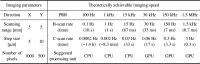
PAM systems require fast imaging capability in both preclinical and clinical applications while maintaining high spatial resolution and signal-to-noise ratios (SNRs) at a deeper depth. The imaging speed of PAM depends upon the laser pulse repetition rate (PRR), a scanning mechanism, signal acquisition, and processing. A variety of fast scanning techniques have been investigated over the years, such as water-immersible micro-electromechanical systems (MEMS) [[71], [72], [73], [74]], water-immersible galvanometers [[75], [76], [77]], voice coils [78], water-immersible polygon-mirrors [79,80], or slider-crank scanners [81]. The computational speed of PAM for real-time signal and image processing is also enhanced by using advanced computer graphics processors. Besides, a variety of approaches have been proposed to improve the imaging speed by using microlens array to overcome the point-by-point scanning [[82], [83], [84]] and by applying the neural network to the sparse data to enhance the quality of low-sampling PAM images [85]. While these showed improved PAM imaging speed, the fundamental limitation for high-speed PAM still remains and is due to the slow laser PRR. The achievable PAM imaging speed with various laser PRRs is shown in Table 1. A typical field of view (FOV) of 5 × 5 mm2 with step sizes of 5 and 10 μm in the X and Y directions is considered in this table. The B-scan (scanning in the X direction to achieve 2D image) and C-scan (scanning in the X and Y directions to achieve 3D image) rates are calculated as follows:
| (1) |
| (2) |
where is the PRR of the light source, (= 1000 pixels) and (= 500 pixels) are the number of pixels in the X and Y directions, respectively. From Table 1, we can deduce that the laser PRR of 30 kHz or higher ensures real-time B-scan imaging (i.e., 30 Hz) rate for the set specification. For the C-scan, the higher the PRR better the imaging speed will be. While generating this table, ideal scanning and fast image generation are assumed. In addition, the propagation time of PA waves from the target objects to the detector also has to be considered during the practical implementation of fast PAM.
Table 1.
The achievable imaging speed and suggested processing unit correspond to various laser PRRs in a typical PAM imaging setting. PRR, pulse repetition rate; PAM, photoacoustic microscopy; CPU, central processing unit; GPU, graphics processing unit.
 |
In this review, we discuss three essential factors required for implementing fast PAM: (1) the fundamental PRR requirements of the laser while avoiding the overlaps of PA signals between two consecutive laser pulses, (2) the fast scanning methods that can operate in a water environment, and (3) the high-performance parallel computing processes (i.e., graphics processing unit, GPU) for real-time image generation. The recent advances in light sources and their application for fast PAM systems are explored. Finally, the potential applications and challenges of fast PAM are also discussed. To the best of our knowledge, this is the first review article investigating the fundamental requirements and limitations of the high-speed PAM with respect to various types and performances of light sources.
2. Requirements for fast photoacoustic microscopy
2.1. Maximum allowable pulse repetition rate
In general, the fast PAM can be achieved using a high laser PRR. However, the PRR cannot be increased unilaterally due to the fundamental limitation of wave propagation and data acquisition time. In PAI, as stated before, the optical absorption by biological tissue results in acoustic (i.e., sound) waves. The relatively slow speed of sound (1540 m/s in biological tissue) enables depth-resolved PAI images, but it could also cause signal aliasing when the PRR of the light source is faster than the critical PRR, i.e., the maximum allowable laser PRR. The critical PRR is determined as a function of the target imaging depth, assuming the data acquisition and storing time is short enough to ignore (Fig. 1a) [86], and is given by:
| (3) |
where is the critical PRR of the light source, is the speed of sound, is the target imaging depth, and is the acoustic propagation time for the signal to arrive from the target imaging depth. We assume that all topically absorbing chromophores generate PA waves for each pulse of light simultaneously because the speed of light is fast enough to neglect the traveling time (Fig. 1b). Once the PA waves are generated from the target, they propagate in all directions and are detected by the transducer (i.e., detector) after time . In an ideal case, all the generated PA waves are recorded (S1 and S2 in Fig. 1c) by the detector at the corresponding traveling time (t1 and t2 in Fig. 1c), and all are detected within the time interval between successive light pulses. If the PRR is higher than the critical PRR, however, the PA waves are generated at target by the next light pulse before all the current waves are detected, resulting in signal aliasing (dashed box in Fig. 1d). Therefore, to ensure that all the generated PA signals are detected, the PRR must be lower than the critical PRR (Fig. 1d).
Fig. 1.

Aliasing of PA signals between the successive laser pulses. (a) The maximum allowable laser pulse repetition rate (PRR) (or called to as critical PRR) as a function of target imaging depth. (b) Schematic illustration of PA wave generated at different depth of position. (c) Schematic illustration for the time sequence of light pulses and corresponding PA signal detection. (d) Schematic illustration of signal aliasing when the PRR exceeds the critical PRR. PRR, pulse repetition rate; PA, photoacoustic; d1 and d2, distances between objects and the detector; S1 and S2, PA signals from objects; t1 and t2, propagation time of PA waves.
For determining the effective target imaging depth of a specific PAI system, the light delivering mechanism of each system should be considered. In general, the fundamental difference between PACT, AR-PAM, and OR-PAM is in the optical focusing mechanism, where each system requires different acceptable focal sizes. In biological tissue, it is difficult to maintain the optical focus in deep tissue due to the strong optical diffusion. The focus can be optical diffusive (> 10 mm), quasi-diffusive (1–10 mm), and ballistic regime (< 1 mm) in PACT (imaging depth: ≤ 5 cm), AR-PAM (imaging depth: ≤ 10 mm), and OR-PAM (imaging depth: ≤ 1 mm), respectively [87]. The acceptable optical focus regime, target imaging depth, and corresponding critical PRR for each imaging method are summarized in Table 2. As we discussed above, the targeting depth determines the critical PRR. Thus, in OR-PAM, the PRR can be increased up to 1.54 MHz for tight optical focus at shallow imaging depth. When this PRR is applied to the typical imaging area of PAM, as described in Table 1, a B-scan imaging rate of ∼1.5 kHz and a 3D imaging rate of ∼3 Hz can be achieved. Although the high PRR in Table 1 shows the potential for fast imaging, one has to consider the overhead from the data acquisition (i.e., scanning) and processing methods, which are not included in the theoretical calculation above.
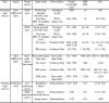
Table 2.
The target depths and critical PRR for different types of PAI systems. PRR, pulse repetition rate; PAI, photoacoustic imaging; PACT, photoacoustic computed tomography; AR-PAM, acoustic-resolution photoacoustic microscopy; OR-PAM, optical-resolution photoacoustic microscopy; , speed of sound in soft tissue.
| PACT | AR-PAM | OR-PAM | |
|---|---|---|---|
| Optical focus regime | Diffusive | Quasi-diffusive | Ballistic regime |
| Effective imaging depth | ≤ 5 cm | ≤ 10 mm | ≤ 1 mm |
| Critical PRR | 30.8 kHz | 154 kHz | 1.54 MHz |
(where 1540 m/s).
2.2. High-speed scanning of optical beams and acoustic waves
Unlike conventional optical imaging techniques, PAM requires mirror and scanning systems to deliver both optical beams and acoustic waves. Wang et al. [78] presented a mechanical scanning device that uses a voice-coil linear translation stage for a fast PAM system. Their system showed fast PAI capability and achieved a B-scan imaging rate of 40 Hz at the scanning range of 1 mm. However, the scanning speed cannot be increased further because of the driving force and the weight of the imaging head. For overcoming the limitations imposed by mechanical scanning, various opto-ultrasound scanning systems have been studied. The three main water-immersible mirror scanning systems are (1) MEMS scanner, (2) galvanometer scanner, and (3) polygon-mirror scanner. The performance overviews of these scanning systems for implementing fast PAM are summarized in Table 3.
Table 3.
Fast imaging performance of scanning systems for photoacoustic microscope. MEMS, micro-electromechanical systems; #, number; -, did not mentioned.
| Scanner type | B-scan |
C-scan |
Lateral resolution [μm] | Ref. | ||||
|---|---|---|---|---|---|---|---|---|
| Rate [Hz] | Range [mm] | # of pixels | Rate [Hz] | Range [mm2] | # of pixels | |||
| Voice-coil | 40 | 1 | – | – | – | – | 3.4 | [78] |
| 1-axis MEMS | 400 | 2 | 250 | 0.8 | 2 × 5 | 250 × 500 | 10 | [71] |
| 2-axis MEMS | 50 | 2 | 200 | 0.25 | 1 × 2 | 100 × 200 | 3.6 | [72] |
| 35 | 2.8 | 700 | 0.05 | 2.8 × 2 | 700 × 700 | 12 | [73] | |
| – | – | – | 3.2 | 2 × 2 | 500 × 500 | 3.8 | [74] | |
| Galvanometer | 250 | 4 | 200 | 0.5 | 4 × 8 | 200 × 500 | 6 | [76] |
| 500 | 2.4 | 500 | 5 | 2.4 × 0.5 | 480 × 500 | 7.5 | [54] | |
| Polygon-mirror | 900 | 12 | – | 0.06 | 20 × 12 | – | 10 | [79] |
| 477.5 | 12 | – | 1 | 12 × 5 | – | 6.3 | [80] | |
The water-immersible MEMS scanners have been developed and applied to fast PAM due to the miniature size, fast response, and cost-efficiency. In 2012, Yao et al. reported a water-immersible MEMS scanner [71], which acquired B-scan at an imaging rate of up to 400 Hz. However, their MEMS scanner only operates along one axis. Thus, C-scan imaging required additional motorized scanning, which was slower than the MEMS scanning. Kim et al. overcame this limitation and presented a fast PAM system based on a 2-axis MEMS scanner that showed scanning rates of 50 and 30 Hz in the X and Y direction, respectively [72]. Due to the fast imaging speed, they could monitor the flow of carbon particles with a C-scan rate of 0.25 Hz. Park et al. improved the system usability by developing a small handheld probe (a diameter of 17 mm and a weight of 162 g) using a 2-axis MEMS scanner [73]. This system showed a maximum imaging region of 2.8 × 2 mm2 at a B-scan rate of 35 Hz. Chen et al. also demonstrated an ultra-compact handheld PAM using a 2-axis MEMS scanner [74]. With a resonant frequency of ∼800 Hz, the developed MEMS scanner could support a C-scan rate of up to 3.2 Hz in an imaging region of 2 × 2 mm2. The water-immersible MEMS scanner could successfully achieve fast PAI of brain activity and flowing carbon particles. However, these water-immersible MEMS scanners are not durable for long-term use and the acquired PA images are often distorted due to unstable scan patterns.
Galvanometer scanners also have been used in PAM to overcome the relatively weak durability of the MEMS scanners. Yuan et al. applied the first 2-axis galvanometer scanning system to PAM in 2012 [75]. However, the fast imaging capability was not evaluated due to the low PRR (15 Hz) of the light source. In 2016, Kim et al. developed a fast PAM system using a 1-axis galvanometer with a maximum B-scan rate of 250 Hz [76]. Particularly, they improved the image SNR by operating the galvanometer scanner in non-conductive liquids, enabling both acoustic and optical scanning simultaneously. By using this system, a volumetric image with a region of 4 × 8 mm2 was successfully acquired in 2 s. In the follow-up study, Kim et al. improved the B-scan rate to 500 Hz by submerging the mirror part of the 1-axis galvanometer in water [77]. The C-scan rate achieved using this system was 5 Hz, which enabled the observation of red blood cells by localizing PA signals. Specifically, they demonstrated improvement in spatial resolution (improved lateral resolution from 7.5 μm to 0.4–0.7 μm and axial resolution from 33 μm to 2.5 μm) using a novel agent-free localization method. Since the galvanometer scanners are commercial products, they have shown stable performance compared to the MEMS scanners. However, the main limitation of galvanometer scanner is the limited FOV, which makes it difficult to scan large region of interest (ROI).
Lan et al. introduced a water-immersible hexagon-mirror scanner to overcome the limited FOV of the MEMS and galvanometer scanner, which provided wide-field PAM with a B-scan rate of up to 900 Hz [79]. This scanner covered up to a 12-mm scanning range while maintaining a coaxial alignment of the optical and acoustic beams. More recently, Chen et al. proposed a polygon-mirror scanner for the fast PAM with a C-scan rate of 1 Hz for a scanning region of 12 × 5 mm2 [80]. They also demonstrated wide-field sO2 mapping in the 12 × 12 mm2 scanning area of the mouse ear with an imaging time of 5 s. The hexagon-mirror scanners are stable with wide scanning ranges since they do not require repeated acceleration and deceleration. However, since the laser beam is often delivered to the undetectable area (∼40 % of the total laser pulses), the overall efficiency of the PAM with hexagonal mirror scanners is low.
2.3. Computational requirements for signal processing
In addition to the previously discussed hardware requirements (i.e., laser PRR and scanning speed), computational speed for signal processing and image generation should also be considered for fast PAM implementation. The computational speed for signal and image processing directly depends on the total size of data points. The size of the data is determined not only from the lateral scanning parameters (i.e., scanning ranges and step sizes) but also from the number of recorded data samples along the axial direction. Thus, the sampling rate of the data acquisition module in PAM determines the size of the data, which in turn determines the number of computations needed. According to the Nyquist theorem, the sampling rate should be at least twice higher than the center frequency of the US transducer. However, for complete signal restoration, prevention of aliasing, and increase of SNRs, the practical sampling rate is generally ∼10 folds higher than the center frequency of the transducer.
Unlike a lateral resolution, which is determined by the spot size of the optical beam or acoustic focus, the axial resolution of PAM is dependent on the frequency bandwidth of the detecting transducer as shown in the following equation [47]:
| (4) |
where is the axial resolution of the system, is the speed of sound, and is the frequency bandwidth of the detected signal. Since the is proportional to the center frequency () of the US transducer, high-frequency (20 MHz or higher) transducers are usually used to achieve high axial resolution in typical OR-PAM. For instance, Zhang et al. reported an axial resolution of 7.6 μm by using a 125 MHz US transducer and a sampling rate of 1 GHz [88]. However, higher the sampling rate higher the number of recorded data in the axial direction, which can be calculated as follows:
| (5) |
where is the number of recorded data points in the axial direction, is the recorded depth, and is the sampling rate. For a 1 mm depth in OR-PAM, the record lengths (i.e., number of data points) in the axial direction for various imaging parameters are summarized in Table 4. To generate Table 4, we used the imaging parameters typical of OR-PAM imaging (scanning range of 5 × 5 mm2, step sizes of 5 and 10 μm in the X and Y directions, respectively) that are listed in Table 1. For a 100-MHz transducer, when a typical 14-bit data acquisition (DAQ) device is used, 325 million data points will be recorded for a single C-scan plane resulting in 542 MB data. However, in practice, the is usually set to 1000 data points. Since the DAQ stores data in the units of byte (8 bits), which requires 2-bytes for each data point, the total data size is much larger (954 MB).
Table 4.
Data size for a single C-scan image in OR-PAM as per the center frequency of detecting transducers. A typical imaging parameters of OR-PAM (5 × 5 mm2 scanning with step sizes of 5 and 10 μm in the X and Y directions, respectively), 14-bit digitization in DAQ, and recording depth of 1 mm are assumed. OR-PAM, optical resolution photoacoustic microscopy; DAQ, data acquisition system; M, millions; MB, mega-bytes.
 |
In low PRR, the time interval between two successive pulses is large enough to perform all the calculations using a central processing unit (CPU), i.e., data storing, signal processing, and imaging generation. However, at high PRR, high-speed signal and image processing for fast image generation should be ensured, and a typical CPU cannot compute in the short time interval between pulses. Mattison et al. introduced real-time frequency demodulation of PA signals using a field-programmable gate array (FPGA) module [89]. They collected and processed volumetric data of 200 × 200 × 200 pixels of a zebrafish heart within 1.76 s at the PRR of 25 kHz. The new FPGA equipped with a fast Fourier transform (FFT) engine further reduces the data transfer and image processing time. Recently, advanced GPUs are widely available to accelerate numerical computations. Kang et al. demonstrated real-time parallel signal processing for PAM that achieved an imaging rate of 0.98 Hz for the volumetric data of 500 × 500 × 736 pixels with a PRR of 300 kHz [90,91]. Xu et al. also introduced GPU-based parallel computing for PAM with a PRR of 100 kHz [92]. They both showed significantly improved (∼80 fold) imaging speed compared to the CPU-based processing. With the further improvements in GPU chipsets, computing and memory storage capability have increased, resulting in real-time PAM imaging. In addition, due to the availability of a large number of high-performance programming libraries and easy-to-use development tools, the users can easily improve their processing speed using high-level languages, such as C or python.
3. Fast photoacoustic microscopy as a function of light source speed
3.1. Conventional light sources
In conventional PAMs, flash lamp-pumped solid-state (FPSS) lasers were mainly used to pump the dye laser due to their extremely high pulse energy of several J [34,93]. Xenon or krypton flash lamps with a wall thickness of 1–2 mm, a bore diameter of 3–19 mm, and a length of 5–100 cm have been widely used for inducing Q-switching solid-state lasers [94]. In the typical structure of FPSS, a flash lamp is mounted in a thin cylindrical tube parallel to a long laser crystal rod (Fig. 2a). The emitted light from the flash lamp is amplified by the stimulated emission of electromagnetic radiation in a cavity consisting of an end mirror, a crystal rod, a Q-switch, and a partial reflection mirror. Although the FPSS lasers can provide high pulse energy, they suffer from a low PRR (up to ∼20 Hz) and a short lifetime of several hundreds of million shots [95].
Fig. 2.

Schematic illustrations of laser sources that used for conventional PAM. The typical configurations of (a) FPSS laser, (b) DPSS laser, (c) dye laser, and (d) an OPO. FPSS, flash lamp pumped solid-state; DPSS, diode-pumped solid-state; OPO, optical parametric oscillator; EM, end mirror; TM, tuning mirror; LRM, low reflectivity mirror; HRM, high reflectivity mirror.
The diode-pumped solid-state (DPSS) lasers are other types of lasers that have been widely used in conventional PAMs. Compared to the FPSS lasers, DPSS lasers utilize high-power semiconductor lasers as pumping light sources (Fig. 2b). Because of the high energy efficiency, DPSS lasers can increase the PRR to ∼100 kHz. Instead of the water-cooling system that is typically used in FPSS lasers, an air-cooling or thermoelectric-cooling system can be used for DPSS lasers. Thus, the size of the entire DPSS lasers can be significantly reduced compared to the FPSS lasers. Besides, semiconductor lasers in the DPSS lasers have a lifetime of 109–1010 shots, which is 10–100 fold longer than the typical lifetime of FPSS lasers [94,95].
Because FPSS and DPSS lasers generate single-wavelength light by using neodymium-doped gain mediums, such as Nd:YAG, Nd:YVO4, and Nd:YLF, additional devices are required for the multi-wavelength generation. In dye lasers, the pump source of FPSS or DPSS lasers generate lasers having a wide range of wavelengths (300–1200 nm) with a typical optical bandwidth of 50–100 nm (Fig. 2c). The output wavelength is determined by the type of organic dye that generates fluorescence light emission. However, the dye lasers are limited by the short lifetime and the potential toxicity of volatile solvents. Instead of organic dyes, Ti:sapphire laser, which uses Titanium-doped sapphire crystal as a gain medium, is pumped by the FPSS or DPSS laser. The large gain bandwidth of Ti3+ ion enables the ultrashort pulse generation and the wide tuning range of about 650–1100 nm, respectively. In addition, a good beam quality of Ti:sapphire crystal allows high output power induced by high pump brightness. The optical parametric oscillator (OPO) is another device that can tune the output wavelength in the range of 400–2300 nm, pumped by the FPSS or DPSS lasers (Fig. 2d). When the pump source is delivered into a nonlinear crystal, such as periodically poled lithium niobate (PPLN) crystal, potassium titanyl phosphate (KTP) crystal, or beta barium borate (BBO) crystal, the signal, and idler beams are produced. The wavelength of the output beams can be tuned by changing the phase-matching condition, including the crystal's temperature, the incident angle of the pump source, and the phase-matching period of the crystal.
3.2. High-speed fiber lasers for fast photoacoustic microscopy
3.2.1. Rare-earth-doped fiber lasers
The conventional lasers discussed in the previous section are difficult to apply to fast PAM due to the limitation of low PRR. Therefore, studies to implement fiber lasers that can provide high PRR have been recently conducted (Fig. 3a) [96]. In the cavity structure of the hybrid end-pumped arrangement, the gain fiber is posed in the optical cavity of mirrors. The bifurcated pump sources are delivered into both ends of fiber through dichroic mirrors. In all-fiber end-pumped configuration, intra-core fiber Bragg gratings (FBGs) deliver the seed lasers instead of the bulk optical mirrors. The FBGs reduce the size of the laser, but they can be easily damaged by the high-power seed lasers or the amplified output lasers. All-fiber intra-pumped configuration with intra-cavity pump source launching is widely used to avoid damages.
Fig. 3.

Schematic illustrations for the typical configurations and principles of the rare-earth-doped fiber lasers, and representative PAM images using the fiber lasers. (a) Configurations of hybrid end-pumped, all-fiber end-pumped, and all-fiber intra-pumped configurations of fiber lasers. (b) Representative in vivo PAM images of mice ear using a Yb3+-doped fiber laser. (c) The C-scan MAP images with a scanning area of 10 × 10 mm2 were acquired in 8 s. The images are reproduced with permission from Ref. [96,102].
Glasses, doped by rare-earth ions such as ytterbium (Yb3+), erbium (Er3+), and thulium (Tm3+), are widely used as gain media for fiber lasers. The various rare-earth ions have their own characteristic of energy state level. Thus, they can generate a specific wavelength of light through absorption and emission of the seed laser [[96], [97], [98], [99]]. The Yb3+-doped laser glasses have strong and wide absorption bands near 915 nm and 976 nm and intense emission bands in the spectral range between 950 nm and 1200 nm. Shi et al. at first introduced a PAM system using a Yb3+-doped fiber laser with a wavelength of 532 nm and PRR of 100 kHz [100]. The subsequent study demonstrated in vivo validation of the system with a 600-kHz Yb3+-doped fiber laser [101]. In 2018, Allen et al. also presented in vivo evaluation of a PAM system with Yb3+-doped fiber laser by acquiring PA images of mice ears (10 × 10 mm2, 8 s) with a PRR of 2 MHz (Fig. 3b). Furthermore, they also observed transient hemodynamics in blood vessels with an imaging rate of 10 Hz (Fig. 3c) [102]. The Er3+-doped fiber lasers have been actively studied and used in optical communication fields because of the demand for 1.5 μm wavelength. For Er3+ ion, the main absorption bands are located near 980 nm, and 1530 nm spectral positions, and the emission wavelength is positioned in the 1.5–1.6 μm spectral range. In 2016, Piao et al. successfully acquired PA signals from human hair with a 200 kHz Er3+-doped fiber laser system with a wavelength of 1600 nm [103]. In a fiber laser using co-doping of Er3+ with a higher concentration of Yb3+, optical pumping takes place into the 980 nm absorption wavelength of Yb3+. Through subsequent energy transfer from Yb3+ to Er3+, and lights at the 1520–1650 nm are emitted [[96], [97], [98]]. Therefore, Er3+/Yb3+-doped fiber laser can use high-power free space or fiber-coupled 915 nm or 980 nm laser diodes and shorter gain fiber than Er3+-doped fiber. Tm3+-doped fiber laser generates lights at 1.47 μm or 1.8–2.0 μm spectral ranges, which is considered as an eye-safe range [99,104,105]. Especially, wavelengths of ∼2 μm can be generated by the cross-relaxation process, which is one of the most efficient ways, using a 790 nm diode laser. Li et al. applied a 1690–1750 nm tunable Tm3+-doped fiber laser with 10 kHz and 50 kHz PRR suitable for peak optical absorption of lipid (e.g., ∼1720 nm) to PAM, and PA images of adipose tissue were obtained [106,107].
3.2.2. Supercontinuum light sources
Although the rare-earth-doped fiber lasers can achieve high PRR, the output wavelength is fixed by the gain medium and the seed laser's wavelength. Thus, the multi-wavelength light sources based on supercontinuum (SC) generation have been studied for multispectral imaging in fast PAM. When a single-wavelength light is delivered through a strong nonlinear medium, the single-wavelength light gets converted into light with broad spectral bandwidth (Fig. 4a) [[108], [109], [110]]. For instance, photonic crystal fibers, which have closely spaced air holes, are widely used as the medium that increases nonlinearity. The SC generation depends on the chromatic dispersion, the length of the fiber, and the characteristic of the pumping laser (i.e., pulse width, peak power, and wavelength). The SC generation can be divided by the pulse width of the pumping laser. For the pumping laser with a pulse width of the femtosecond regime, the spectral broadening is caused dominantly by the self-phase modulation and the soliton-related propagation effects of the fiber [[109], [110], [111]]. On the other hand, pumping lasers with a longer pulse width (from the picoseconds to the continuous regime), four-wave mixing, or Raman scattering causes the spectral broadening in the anomalous dispersion regime where the wavelength of the pump source (λpump) is longer than the zero-dispersion wavelength of the nonlinear fiber (λ0) [109]. The four-wave mixing, which is a third-order nonlinear effect, occurs when lights with more than two different frequencies propagate together in a nonlinear medium. The wide spectral broadening can be generated in a high spatial and temporal coherence, which depends on several parameters, including the pulse width and the energy of the pump source, the length of the fiber, and the dispersion of the fiber.
Fig. 4.

Schematic illustration of the configuration of SC source and representativein vivoPA images using an SC source. (a) Schematic illustration for the configuration and multispectral generation of the SC light source. The inset photo is an example of the continuous spectrum dispersed by a diffraction grating. (b) in vivo PAM images of a Xenopus laevis tadpole using SC source with the filtered six spectral bands (1600, 1640, 1680, 1720, 1760 nm) and a PRR of 100 kHz. SC, supercontinuum; λpump, the wavelength of pump source; λ0, zero-dispersion wavelength of nonlinear fiber; PAM, photoacoustic microscopy; PRR, pulse repetition rate. The images are reproduced with permission from Ref. [116].
The SC source, which has the advantage of wavelength tunability, was first applied to PAM by Billeh et al. in 2010 [112]. They used a laser with a PRR of 6.6 kHz and a wavelength tuning region of 600–1700 nm, confirming the multispectral PAI of colored ink samples. In 2013, Lee et al. developed a system that combines PAM and optical coherence tomography (OCT) by using a single SC fiber laser with a PRR of 21 kHz and a wavelength range of 500–1600 nm [113]. Later, they demonstrated the monitoring of sO2 level from in vitro experiments using the SC laser-based PAM [6]. Despite the wavelength tunability, the SC fiber lasers suffer from low pulse energy (generally less than several tens nJ with a bandwidth of 1 nm per pulse) because the spectral energy density decreases as the output bandwidth broadens continuously over hundreds nm. Shu et al. introduced a master oscillator power amplifier (MOPA) laser system in 2016 to achieve higher pulse energy [114]. They demonstrated multispectral PA measurement from in vivo imaging. Chang et al. implemented a real-time imaging system, which acquired multispectral PAM and OCT images simultaneously [115]. They achieved in vivo images of mice ears with a PRR of 1 MHz. More recently, Dasa et al. demonstrated an SC source for lipids detection by using the property of the first overtone transition of carbon-hydrogen vibration bonds (1650−1850 nm) [116]. This source can generate an output laser with a wavelength range of 1440–1870 nm, a pulse width of ∼7 ns, and pulse energy of 18.3 μJ (at a PRR of 100 kHz). They reported multispectral PAM images of lipids from in vivo Xenopus laevis tadpoles using six (1600, 1640, 1680, 1720, 1760, and 1800 nm) different excitation wavelengths (Fig. 4b).
3.2.3. Stimulated raman scattering light sources
To overcome the relatively low pulse energy of multi-wavelength light sources, stimulated Raman scattering (SRS) light sources have been developed. The SRS sources generate cascaded narrow bandwidth outputs, including much higher spectral energy density in each discrete multispectral Stokes wave [117]. The SRS is a nonlinear process that provides enhanced pulse energy in a narrow band with a high PRR [118]. In SRS, more than 10 % of the pumping laser energy can be converted to the Stokes wave energy, which generates the frequency-downshifted radiation. Silica optical fibers are typically used for the medium due to their good efficiency for the frequency shift (13.2 THz) [119]. The Raman threshold power () depends on the maximum Raman gain coefficient (), the effective area (), and the effective length () of the medium through the following equation [111]:
| (6) |
where is the polarization factor. When the is decreased by decreasing or increasing , the same amount of pump power is needed to convert the pump light energy to Stokes light energy [118]. In a normal dispersion regime, pumping laser with a longer pulse dominantly causes Raman effects because self-phase-modulation does not cause a major effect. Discrete Stokes wave extends to the ZDW since four-wave mixing progressively plays an important role closer to the ZDW [120]. The inset is the representative discrete spectra of SRS, showing 9th order Stokes wavelength dispersed by a diffraction grating in a single-mode polarization-maintaining fiber (SM-PMF) pumped by a wavelength of 532 nm (Fig. 5a).
Fig. 5.

Schematic illustration of the configuration of SRS source and representativein vivoPA images using an SRS source. (a) Schematic illustration for the configuration and multispectral generation of the SC light source. The inset photo is an example of the discrete SRS spectrum dispersed by a diffraction grating. (b) in vivo multi-spectral PAM image of cerebral blood vessels in a mouse. (c) in vivo sO2 map in mouse ear based on the multispectral PAM images. (d) Molecular PAM images of gold nanorods in mouse ear. SRS, stimulated Raman scattering; λpump, the wavelength of pump source; λ0, zero-dispersion wavelength of nonlinear fiber; PAM, photoacoustic microscopy; PRR, pulse repetition rate; sO2, hemoglobin oxygen saturation. The images are reproduced with permission from Ref. [80,124,127].
Several studies have been reported implementing fast PAM by using the SRS light sources. Koeplinger et al. demonstrated multispectral PAM by using SM-PMF-based SRS with a PRR of 7.5 kHz [121]. Loya et al. then extended this concept using large-mode-area photonic crystal fibers to generate the multiple wavelength peaks [122]. In 2013, Hajireza et al. first acquired in vivo multispectral PA images using an SRS light source and successfully demonstrated in vivo sO2 level mapping by using 545 nm and 588 nm wavelengths [123]. Later, Wang et al. simultaneously achieved the sO2 level and blood flow in cerebral blood vessels in vivo (Fig. 5b) [124]. They switched the wavelength of a 300-kHz SRS light source by using polarization modulation of an electro-optical modulator. In 2017, Liang et al. also performed functional PAM with improved imaging speed using a 1-MHz SRS light source [125]. More recently, Chen et al. successfully acquired sO2 mapping of a relatively large area of 12 × 12 mm2 with a total imaging time of 5 s (Fig. 5c) [80,126]. They combined a fast polygon scanner with a 1-MHz SRS light source. Further, Park et al. also demonstrated a real-time PAM using an SRS light source that quickly (PRR of 150 kHz) switched two wavelengths (545 nm and 655 nm) by using polarization modulation of an electro-optical modulator [127]. By using the fast wavelength switching, they successfully delineated the exogenous contrast agents from blood vessels in real-time (Fig. 5d).
3.2.4. Active mode-locked lasers
Multi-wavelength light sources with high pulse energy over hundreds nJ and high PRR with hundreds kHz can also be implemented with an active mode-locked (AML) laser. The AML generates high PRR of ultrashort pulses using an optical modulator, an active element that synchronizes the modulation time of the optical modulator and the round-trip time of the laser resonator. The conventional AML lasers produce high PRR (tens of MHz), but the pulse energy is relatively low, typically several hundreds of pJ to several nJ. The modulation frequency (), which is directly proportional to the PRR of the out laser, is determined by the free spectral range (FSR) and the mode-locking order () as shown below:
| (7) |
where c is the speed of light in a vacuum, and FSR is related to the effective refractive index in the medium () and the laser cavity length (). The laser output with multiple wavelengths can be discretely generated by switching different values of ’ s, which correspond to different laser resonating lengths (Fig. 6a). When two cavities of ’ s are constructed by both FBG 1 and 2 having different FSR’s, the lasing wavelength can be selected by switching between two values. Increasing the by adding a cavity fiber, a multi-wavelength AML fiber laser with a much lower PRR of several hundreds of kHz can be generated. It results in a laser with high energy of several hundred nJ and an optimal pulse duration of few nanoseconds. This laser is sufficient to generate a PA signal experimentally, thus feasible for PAM imaging (Fig. 6b) [128]. They used Er3+-doped fiber for the rapid wavelength switching between 1580 nm and 1598 nm under a low-order mode-locking. Depending on the mode-locking order, it was possible to tune the PRR of the laser from 200 kHz to 1 MHz.
Fig. 6.

Schematic illustration of the configuration of AML laser and representative PA signals using an AML laser. (a) Schematic illustration for the configuration of AML laser and wavelength selection by tuning the mpdulation frequency. (b) PA signals from a target object using AML laser generating wavelengths of 1580 and 1598 nm with PRRs of 245 and 260 kHz, respectively. AML; active mode-locked; FBG, fiber Bragg grating; LD, laser diode; L, the cavity length; fm, the mode-locking frequency corresponding; PA, photoacoustic; PRR, pulse repetition rate. The graphs are reproduced with permission from Ref. [128].
3.3. Probing light sources for fast noncontact photoacoustic microscopy
In conventional PAM, the US transducers are typically used for detecting PA waves. However, a coupling medium (i.e., water) is necessary between the tissue surface and the transducer to deliver the PA waves. The typical distance between the target surface and the detecting position is 10–20 mm, which corresponds to 6–12 μs of acoustic travel time. When using high PRR, the additional acoustic travel times through the coupling medium limits the imaging speed by increasing the total data acquisition time for a single laser pulse. By replacing the US transducers with all-optical probing methods using Fabry-Perot sensor [[129], [130], [131]] and noncontact PAM techniques, this limit could be overcome. Thus, it can increase the imaging speed since the overhead time through the medium is reduced and approach close to the theoretical limitation value. Recently, some applications require noncontact measurements, e.g., to avoid infection or to measure electrical components that cannot be immersed in water [132], where noncontact probing method which is no need for physical contact or delivery medium will be beneficial. Here, we explore the noncontact probing methods and probing light sources for fast signal detection.
3.3.1. Noncontact probing methods
The noncontact probing methods can be divided into two categories based on the usage of an interferometer: interferometric and non-interferometric approaches. Of these two, the interferometric method, which measures the phase divergence in surface vibration, is most commonly used in the noncontact detection of PA waves [133]. In the interferometer, the two different beam paths interfere with each other and generate an interference pattern that varies corresponding to the vibration (i.e., PA waves) at the sample surface. The interferometric method can be further divided into homodyne and heterodyne detection methods depending on the frequency shifter. In the homodyne interferometer, the interference between two beam paths (red and blue paths in Fig. 7a) occurs at the same frequency. The PA intensity is measured by extracting the phase difference between two beam paths. In the heterodyne interferometer, the frequency of the reference beam (blue beam in Fig. 7b) is shifted by a frequency shifter and the two different frequencies of the beam paths (red and blue paths in Fig. 7b) generate interference corresponding the difference of the frequencies. The phase difference in the up-shifted frequency is typically measured by an in-phase and quadrature (IQ) demodulation system, which also filters out the electromagnetic interference signals. Thus, in general, heterodyne interferometers are robust to the background noise than homodyne interferometers [[133], [134], [135], [136]]. Compared to the interferometric method, the non-interferometric approach extracts PA signals by measuring the intensity change of the back-reflected probing light source induced by the initial pressure (Fig. 7c) [[137], [138], [139], [140]]. In this method, the probing and the excitation light sources are co-axially focused on generating the strongest pressure. The initial pressure causes an elasto-optical refractive index modulation, which leads to intensity changes in the detector.
Fig. 7.

Schematic illustration for the non-contact detection of PA signals. Schematic illustration of (a) homodyne interferometer, (b) heterodyne interferometer, and (c) non-interferometric detection.
3.3.2. Probing light sources for acoustic signal detection
For the noncontact detection, three types of light sources have been investigated: (1) broadband (low coherence) source, (2) narrow-linewidth (single-frequency) source, and (3) swept-source (Table 5). The broadband sources are most commonly used in the homodyne interferometers (Fig. 8a) [141,142]. In the noncontact PAM, the displacement of the surface vibration is in the scale of several nanometers. By using the short coherence length of the broadband source, sufficient sensitivity of the signal can be achieved when light with a spectral bandwidth of several tens of nanometers is used. Low coherence property can avoid the interference signals from environmental vibration that occurs over the coherence length region. The probing light source with short coherence length is preferred to intentionally reject the local interference signal between the target and surface. The broadband sources also can be used in the non-interferometric method. However, the broadband light sources are not suitable for the heterodyne interferometers because the frequency shift in the broad spectral bandwidth is not effective.
Table 5.
Light sources and probing methods for non-contact detection of the photoacoustic signal. PRR, pulse repetition rate.
| Light source | Probing method | PRR of the excitation source | Bandwidth of detector | Sampling rate | Number of average | Z-scan required | Ref. |
|---|---|---|---|---|---|---|---|
| Broadband source | Homodyne | 40 Hz | 75 MHz | 200 Ms/s | 10 | No | [141] |
| Non-interferometric | 600 kHz | 150 MHz | 200 Ms/s | 1 | Yes | [139] | |
| Narrow-linewidth source | Homodyne | 1 kHz | 100 MHz | 200 Ms/s | 1 | No | [143] |
| Heterodyne | 20 Hz | 350 MHz | 100 Ms/s | 30 | No | [147] | |
| Swept-source | Homodyne | 5 kHz | 150 MHz | 250 Ms/s | 200 | No | [150] |
Fig. 8.

Schematic diagram for the output wavelength bandwidth of probing light sources. (a) Broadband source, (b) narrow-linewidth source, and (c) swept-source.
The narrow-linewidth sources can overcome the limitations of the broadband sources in the homodyne interferometer. This is because the sensitivity of the broadband sources is significantly decreased when the optical path difference is not in the coherence length region (Fig. 8b) [143]. Thus, narrow-linewidth sources have been widely used in applications that require long-term stability of the light sources, including fiber-optic sensors and light detection and ranging (LIDAR) systems [144]. The sensitivity of the narrow-linewidth sources can be maintained for a large dynamic range due to its long coherence length. Besides, they are also used in heterodyne interferometers because of their high spectral purity, which enables low phase noise [145,146]. Thus, narrow-linewidth sources are used as a probing light source in both interferometric methods [143,[147], [148], [149]].
In the swept-sources, the center wavelength in a narrow spectral linewidth of a few picometers is periodically modulated (Fig. 8c). The high-speed DAQ devices are used to acquire the data with a combination of the swept-source, resulting in fast signal detection compared to the combination of a broadband source and a spectrometer. Bratter et al. demonstrated the PA signal detection using a swept-source with a sweeping rate of 110 kHz [150]. They collected the interferences in a range of several MHz with a sampling rate of 250 MHz. Since high-speed detection is required in several fields, the high-speed modulation technique has been continuously investigated and developed. Thus, the swept-source has the potential of being used as a probing light source for fast noncontact PAM due to the sweeping rate in the order of MHz [[151], [152], [153], [154]].
4. Discussion and conclusion
In this review article, we discussed the requirements and current status of light sources for fast PAMs. Since PAI is a promising biomedical imaging tool capable of achieving strong optical contrast at relatively deep imaging depths, it has great potential to expand research applications further using fast imaging speed. As we presented in the introduction, there are mainly three possibilities to achieve fast PAMs: (1) high PRR, (2) fast scanning method, and (3) high computing power. To date, researchers have been primarily focused on improving scanning speed and computational efficiency to improve PAM imaging speed. However, since high PRR is a fundamental factor that can directly increase the imaging speed, researchers in recent years are actively studying light sources with high PRR. In general, fast PAI is more feasible for the OR-PAM since the output pulse energy decreases with the increase in PRR. In addition, since the critical PRR, which avoids aliasing of signals between two subsequent pulses, is directly related to the target imaging depth, the relatively shallow imaging depth (∼1 mm) of OR-PAM allows very high PRR and can be increased to ∼1.54 MHz.
We also presented in-depth the principles and characteristics of various light sources for PAMs. The representative light sources and their characteristics for PAMs are summarized in Table 6. The rare-earth-doped fiber lasers have been explored to overcome the low PRR of the conventional Q-switched solid-state lasers. However, they can only generate single-wavelength output, limiting the multispectral response analysis of the biological tissue. Thus, SC and SRS light sources have been applied to achieve multispectral PA responses by tuning the output wavelengths with PRRs higher than 100 kHz. Besides, laser diodes and LEDs have been reported as alternate light source for low-cost PAM [155]. In addition, noncontact PA detection methods have shown the feasibility for further improvement of imaging speed by removing the wave propagation time between the imaging surface and the US transducer detector. For noncontact PA detection, several probing methods and light sources have been introduced and studied.
Table 6.
Summary of light sources for fast PAM. PRR, pulse repetition rate; FPSS, flash lamp-pumped solid-state; DPSS, diode-pumped solid-state; OPO, optical parametric oscillator; SC, supercontinuum; SRS, stimulated Raman scattering; AML, active mode-locked; PPLN, periodically poled lithium niobate.
 |
The development of these key technologies would potentially provide an opportunity for a variety of multispectral PA investigations, such as real-time sO2 mapping, blood flow measurement, and brain hemodynamics observation. However, there are several challenges that still remain to be overcome for the fast PAM: (1) high pulse energy (from several nJ to hundreds of μJ) with high PRR, (2) tunable output wavelength in the region of NIR-I (650–950 nm) or NIR-II (1000–1700 nm), and (3) fast enough scanning and image processing time. In the near future, by overcoming these challenges, the application areas of PAI can be significantly expanded to include not only preclinical applications but also clinical studies that require fast imaging speed.
Declaration of Competing Interest
Chulhong Kim has financial interests in OPTICHO, which, however, did not support this work. The authors declare no conflicts of interest.
Acknowledgments
This work was supported by the National Research Foundation of Korea (NRF) grant funded by the Korea government (MSIT, MOE) (2018M3D1A1058814, 2019R1A2C2006269, 2020M3H2A1078045, 2021R1A5A1032937, 2020R1A6A1A03047901) and the Korea Medical Device Development Fund (KMDF) grants funded by the Korean government (MSIT, MOTIE, MOHW, and MFDS) (KMDF_PR_20200901_0024(1711137935), KMDF_PR_20200901_0026(1711137946), KMDF_PR_20200901_0055(1711138045)), and 2021 BK21 FOUR Programs (Pohang University of Science and Technology, Pusan National University). It was also supported by the Commercialization Promotion Agency for R&D Outcomes(COMPA) funded by Korean government (MSIT) (1711123345) and Development of Measurement Standards and Technology for Biomaterials and Medical Convergence funded by the Korea Research Institute of Standards and Science (KRISS) (KRISS-2021-GP2021-0004).
Biographies

Soon-Woo Cho received the M.S. degree from the Department of Cogno-Mechatronics Engineering, Pusan National University, Busan, South Korea, in 2016. She is currently working toward the Ph.D. degree at the Department of Cogno-Mechatronics Engineering, Pusan National University. Her current research interests include the development of photoacoustic microscopy, and optical coherence microscopy using novel fiber laser system for biomedical applications.

Sang Min Park received the M.S. degree from the Department of Cogno-Mechatronics Engineering, Pusan National University, Busan, South Korea, in 2018. He is currently working toward the Ph.D. degree at the Department of Cogno-Mechatronics Engineering, Pusan National University. His current research interests include the development of nonlinear fiber laser and optical imaging system for biomedical applications.

Byullee Park received his Ph.D. degree in Creative IT Engineering at Pohang University of Science and Technology (POSTECH) in Republic of Korea from 2015 to 2020. He is currently undertaking a post-doctoral researcher training course at POSTECH (2021∼). His research interests are the development of novel biomedical imaging techniques including sub-wavelength photoacoustic microscopy and clinical photoacoustic/ultrasound imaging.

Do Yeon Kim is currently working toward the Ph. D. degree at the Department of Bio-Convergence Engineering, Korea University and at the Safety Measurement Institute, Korea Research Institute of Standards and Science, Daejeon, South Korea. Current research interests include the photoacoustic microscopy.

Tae Geol Lee received the M.S. and Ph. D. degrees in physical chemistry from Seoul National University, Korea in 1998. He is a Principal Research Scientist and the Head with the Center for Nano-Bio Measurement, Korea Research Institute of Standards and Science, Daejeon, South Korea. His current research interests include the studying quantitative surface analysis/imaging of organic/bio-samples (bio-chips, cells, tissue, and nanoparticles, etc.) using ToF-SIMS, MALDI-TOF, photoacoustic imaging, SERS and AFM techniques for medical applications.

Beop-Min Kim received the B.S. degree from the Department of Mechanical Engineering, Korea University, Seoul, Korea, in 1989, and the M.S. and Ph.D. degrees from the Department of Biomedical Engineering, Texas A&M University, College Station, in 1991 and 1996, respectively. From 1996–2001, he was with the Lawrence Livermore National Laboratory, Livermore, CA, as a Research Fellow of biomedical optics. He is currently a Professor at the Department of Biomedical Engineering, Korea University, Seoul, South Korea. His current research interests include the near-IR spectroscopy in neuroscience, nonlinear optical microscopy, intraoperative optical imaging system, and optical coherence tomography.
Chulhong Kim received his Ph.D. degree in biomedical engineering from Washington University, St. Louis, MO. He currently holds Mueunjae Chair Professorship and is a Professor of Electrical Engineering, Convergence IT Engineering, Mechanical Engineering, and Interdisciplinary Bioscience and Bioengineering at POSTECH. His research interests are the development of novel biomedical imaging techniques including photoacoustic tomography, ultrasound-modulated optical tomography, fluorescence imaging, ultrasound imaging, and laser speckle contrast imaging.

Jeesu Kim received his Ph.D. degree in the Department of Electrical Engineering at Pohang University of Science and Technology. He is an Assistant Professor in the Department of Cogno-Mechatronics Engineering at Pusan National University. His research interests focus on the development of non-ionizing and non-invasive biomedical imaging techniques including photoacoustic, ultrasound, and fluorescence imaging, and their applications to clinical studies.

Sang-Won Lee received the Ph.D. degree from the Department of Biomedical Engineering, Yonsei University, Wonju, South Korea, in 2008. He is a Principal Research Scientist with Safety Measurement Institute, Korea Research Institute of Standards and Science, Daejeon, South Korea. His current research interests include the development of optical-resolution photoacoustic microscopy, nonlinear optical microscopy, and optical coherence microscopy/tomography for biomedical applications.

Chang-Seok Kim received the Ph.D. degree from The Johns Hopkins University, Baltimore, MD, USA, in2004. He is a Professor with the Department of Optics and Mechatronics Engineering and the Department of Cogno-Mechatronics Engineering, Pusan National University, Busan, South Korea. His current research interests include the development of novel fiber laser systems and application of them into biomedical, telecommunication, and sensor areas.
Contributor Information
Jeesu Kim, Email: jeesukim@pusan.ac.kr.
Sang-Won Lee, Email: swlee76@kriss.re.kr.
Chang-Seok Kim, Email: ckim@pusan.ac.kr.
References
- 1.Bell A.G. The photophone. Science. 1880;1(11):130–134. doi: 10.1126/science.os-1.12.130. [DOI] [PubMed] [Google Scholar]
- 2.Kim J., Lee D., Jung U., Kim C. Photoacoustic imaging platforms for multimodal imaging. Ultrasonography. 2015;34(2):88. doi: 10.14366/usg.14062. [DOI] [PMC free article] [PubMed] [Google Scholar]
- 3.Wang L.V. Multiscale photoacoustic microscopy and computed tomography. Nat. Photonics. 2009;3(9):503–509. doi: 10.1038/nphoton.2009.157. [DOI] [PMC free article] [PubMed] [Google Scholar]
- 4.Kim C., Favazza C., Wang L.V. In vivo photoacoustic tomography of chemicals: high-resolution functional and molecular optical imaging at New Depths. Chem. Rev. 2010;110(5):2756–2782. doi: 10.1021/cr900266s. [DOI] [PMC free article] [PubMed] [Google Scholar]
- 5.Wang X., Stoica G., Xie X., Ku G., Wang L.V. Noninvasive imaging of hemoglobin concentration and oxygenation in the rat brain using high-resolution photoacoustic tomography. J. Biomed. Opt. 2006;11(2) doi: 10.1117/1.2192804. 024015-024015-9. [DOI] [PubMed] [Google Scholar]
- 6.Lee C., Jeon M., Jeon M.Y., Kim J., Kim C. In vitro photoacoustic measurement of hemoglobin oxygen saturation using a single pulsed broadband supercontinuum laser source. Appl. Opt. 2014;53(18):3884–3889. doi: 10.1364/AO.53.003884. [DOI] [PubMed] [Google Scholar]
- 7.Choi C., Ahn J., Kim C. Intravascular photothermal strain imaging for lipid detection. Sensors. 2018;18(11):3609. doi: 10.3390/s18113609. [DOI] [PMC free article] [PubMed] [Google Scholar]
- 8.Zhou Y., Tripathi S.V., Rosman I., Ma J., Hai P., Linette G.P., Council M.L., Fields R.C., Wang L.V., Cornelius L.A. Noninvasive determination of melanoma depth using a handheld photoacoustic probe. J. Invest. Dermatol. 2017;137(6):1370–1372. doi: 10.1016/j.jid.2017.01.016. [DOI] [PMC free article] [PubMed] [Google Scholar]
- 9.Bastuji‐Garin S., Diepgen T. Cutaneous malignant melanoma, sun exposure, and sunscreen use: epidemiological evidence. Br. J. Dermatol. 2002;146(s61):24–30. doi: 10.1046/j.1365-2133.146.s61.9.x. [DOI] [PubMed] [Google Scholar]
- 10.Zhang Y., Jeon M., Rich L.J., Hong H., Geng J., Zhang Y., Shi S., Barnhart T.E., Alexandridis P., Huizinga J.D. Non-invasive multimodal functional imaging of the intestine with Frozen micellar naphthalocyanines. Nat. Nanotechnol. 2014;9(8):631–638. doi: 10.1038/nnano.2014.130. [DOI] [PMC free article] [PubMed] [Google Scholar]
- 11.Lee C., Kim J., Zhang Y., Jeon M., Liu C., Song L., Lovell J.F., Kim C. Dual-color photoacoustic lymph node imaging using nanoformulated naphthalocyanines. Biomaterials. 2015;73:142–148. doi: 10.1016/j.biomaterials.2015.09.023. [DOI] [PubMed] [Google Scholar]
- 12.Song J., Kim J., Hwang S., Jeon M., Jeong S., Kim C., Kim S. “Smart” gold nanoparticles for photoacoustic imaging: an imaging contrast agent responsive to the cancer microenvironment and signal amplification via pH-induced aggregation. Chem. Commun. 2016;52(53):8287–8290. doi: 10.1039/c6cc03100e. [DOI] [PubMed] [Google Scholar]
- 13.Park S., Park G., Kim J., Choi W., Jeong U., Kim C. Bi2Se3 nanoplates for contrast-enhanced photoacoustic imaging at 1064 nm. Nanoscale. 2018;10(44):20548–20558. doi: 10.1039/c8nr05672b. [DOI] [PubMed] [Google Scholar]
- 14.Jung H., Park S., Gunassekaran G.R., Jeon M., Cho Y.-E., Baek M.-C., Park J.Y., Shim G., Oh Y.-K., Kim I.-S. A peptide probe enables photoacoustic-guided imaging and drug delivery to lung tumors in K-rasLA2 mutant mice. Cancer Res. 2019;79(16):4271–4282. doi: 10.1158/0008-5472.CAN-18-3089. [DOI] [PubMed] [Google Scholar]
- 15.Wu Y., Sun L., Zeng F., Wu S. A conjugated-polymer-based ratiometric nanoprobe for evaluating in-vivo hepatotoxicity induced by herbal medicine via MSOT imaging. Photoacoustics. 2019;13:6–17. doi: 10.1016/j.pacs.2018.11.002. [DOI] [PMC free article] [PubMed] [Google Scholar]
- 16.Park B., Lee K.M., Park S., Yun M., Choi H.-J., Kim J., Lee C., Kim H., Kim C. Deep tissue photoacoustic imaging of nickel (II) dithiolene-containing polymeric nanoparticles in the second near-infrared window. Theranostics. 2020;10(6) doi: 10.7150/thno.39403. 2509. [DOI] [PMC free article] [PubMed] [Google Scholar]
- 17.Wang L.V., Hu S. Photoacoustic tomography: in vivo imaging from organelles to organs. Science. 2012;335(6075):1458–1462. doi: 10.1126/science.1216210. [DOI] [PMC free article] [PubMed] [Google Scholar]
- 18.Kim J., Park S., Jung Y., Chang S., Park J., Zhang Y., Lovell J.F., Kim C. Programmable real-time clinical photoacoustic and ultrasound imaging system. Sci. Rep. 2016;6:35137. doi: 10.1038/srep35137. [DOI] [PMC free article] [PubMed] [Google Scholar]
- 19.Gateau J., Caballero M.Á.A., Dima A., Ntziachristos V. Three‐dimensional optoacoustic tomography using a conventional ultrasound linear detector array: whole‐body tomographic system for small animals. Med. Phys. 2013;40(1) doi: 10.1118/1.4770292. [DOI] [PubMed] [Google Scholar]
- 20.Razansky D., Buehler A., Ntziachristos V. Volumetric real-time multispectral optoacoustic tomography of biomarkers. Nat. Protoc. 2011;6(8):1121–1129. doi: 10.1038/nprot.2011.351. [DOI] [PubMed] [Google Scholar]
- 21.Na S., Yuan X., Lin L., Isla J., Garrett D., Wang L.V. Transcranial photoacoustic computed tomography based on a layered back-projection method. Photoacoustics. 2020;20 doi: 10.1016/j.pacs.2020.100213. [DOI] [PMC free article] [PubMed] [Google Scholar]
- 22.Cui M., Zuo H., Wang X., Deng K., Luo J., Ma C. Adaptive photoacoustic computed tomography. Photoacoustics. 2021;21 doi: 10.1016/j.pacs.2020.100223. [DOI] [PMC free article] [PubMed] [Google Scholar]
- 23.Toi M., Asao Y., Matsumoto Y., Sekiguchi H., Yoshikawa A., Takada M., Kataoka M., Endo T., Kawaguchi-Sakita N., Kawashima M. Visualization of tumor-related blood vessels in human breast by photoacoustic imaging system with a hemispherical detector array. Sci. Rep. 2017;7:41970. doi: 10.1038/srep41970. [DOI] [PMC free article] [PubMed] [Google Scholar]
- 24.Li L., Zhu L., Ma C., Lin L., Yao J., Wang L., Maslov K., Zhang R., Chen W., Shi J. Single-impulse panoramic photoacoustic computed tomography of small-animal whole-body dynamics at high spatiotemporal resolution. Nat. Biomed. Eng. 2017;1(5):1–11. doi: 10.1038/s41551-017-0071. [DOI] [PMC free article] [PubMed] [Google Scholar]
- 25.Luís Deán-Ben X., Razansky D. Adding fifth dimension to optoacoustic imaging: volumetric time-resolved spectrally enriched tomography. Light Sci. Appl. 2014;3(1):e137. [Google Scholar]
- 26.Manohar S., Kharine A., van Hespen J.C., Steenbergen W., van Leeuwen T.G. The Twente Photoacoustic Mammoscope: system overview and performance. Phys. Med. Biol. 2005;50(11):2543. doi: 10.1088/0031-9155/50/11/007. [DOI] [PubMed] [Google Scholar]
- 27.Choi W., Park E.-Y., Jeon S., Kim C. Clinical photoacoustic imaging platforms. Biomed. Eng. Lett. 2018:1–17. doi: 10.1007/s13534-018-0062-7. [DOI] [PMC free article] [PubMed] [Google Scholar]
- 28.Jeon S., Park E.-Y., Choi W., Managuli R., jong Lee K., Kim C. Real-time delay-multiply-and-sum beamforming with coherence factor for in vivo clinical photoacoustic imaging of humans. Photoacoustics. 2019;15 doi: 10.1016/j.pacs.2019.100136. [DOI] [PMC free article] [PubMed] [Google Scholar]
- 29.Steinberg I., Huland D.M., Vermesh O., Frostig H.E., Tummers W.S., Gambhir S.S. Photoacoustic clinical imaging. Photoacoustics. 2019;14:77–98. doi: 10.1016/j.pacs.2019.05.001. [DOI] [PMC free article] [PubMed] [Google Scholar]
- 30.Han M., Choi W., Ahn J., Ryu H., Seo Y., Kim C. In vivo dual-modal photoacoustic and ultrasound imaging of sentinel lymph nodes using a solid-state dye laser system. Sensors. 2020;20(13):3714. doi: 10.3390/s20133714. [DOI] [PMC free article] [PubMed] [Google Scholar]
- 31.Lee C., Choi W., Kim J., Kim C. Three-dimensional clinical handheld photoacoustic/ultrasound scanner. Photoacoustics. 2020;18 doi: 10.1016/j.pacs.2020.100173. [DOI] [PMC free article] [PubMed] [Google Scholar]
- 32.Chen Q., Qin W., Qi W., Xi L. Progress of clinical translation of handheld and semi-handheld photoacoustic imaging. Photoacoustics. 2021 doi: 10.1016/j.pacs.2021.100264. [DOI] [PMC free article] [PubMed] [Google Scholar]
- 33.Steinberg I., Kim J., Schneider M.K., Hyun D., Zlitni A., Hooper S.M., Klap T., Sonn G.A., Dahl J.J., Kim C. Superiorized photo-acoustic Non-NEgative reconstruction (SPANNER) for clinical photoacoustic imaging. IEEE Trans. Med. Imaging. 2021 doi: 10.1109/TMI.2021.3068181. [DOI] [PubMed] [Google Scholar]
- 34.Lin L., Hu P., Shi J., Appleton C.M., Maslov K., Li L., Zhang R., Wang L.V. Single-breath-Hold photoacoustic computed tomography of the breast. Nat. Commun. 2018;9(1):2352. doi: 10.1038/s41467-018-04576-z. [DOI] [PMC free article] [PubMed] [Google Scholar]
- 35.Heijblom M., Steenbergen W., Manohar S. Clinical photoacoustic breast imaging: the twente experience. IEEE Pulse. 2015;6(3):42–46. doi: 10.1109/MPUL.2015.2409102. [DOI] [PubMed] [Google Scholar]
- 36.Chitgupi U., Nyayapathi N., Kim J., Wang D., Sun B., Li C., Carter K., Huang W.C., Kim C., Xia J. Surfactant‐stripped micelles for NIR‐II photoacoustic imaging through 12 cm of breast tissue and whole human breasts. Adv. Mater. 2019 doi: 10.1002/adma.201902279. [DOI] [PMC free article] [PubMed] [Google Scholar]
- 37.Kothapalli S.-R., Sonn G.A., Choe J.W., Nikoozadeh A., Bhuyan A., Park K.K., Cristman P., Fan R., Moini A., Lee B.C., Wu J., Carver T.E., Trivedi D., Shiiba L., Steinberg I., Huland D.M., Rasmussen M.F., Liao J.C., Brooks J.D., Khuri-Yakub P.T., Gambhir S.S. Simultaneous transrectal ultrasound and photoacoustic human prostate imaging. Sci. Transl. Med. 2019;11(507) doi: 10.1126/scitranslmed.aav2169. eaav2169. [DOI] [PubMed] [Google Scholar]
- 38.Napoli A., Anzidei M., De Nunzio C., Cartocci G., Panebianco V., De Dominicis C., Catalano C., Petrucci F., Leonardo C. Real-time magnetic resonance–guided high-intensity focused ultrasound focal therapy for localised prostate cancer: preliminary experience. Eur. Urol. 2013;63(2):395–398. doi: 10.1016/j.eururo.2012.11.002. [DOI] [PubMed] [Google Scholar]
- 39.Horiguchi A., Tsujita K., Irisawa K., Kasamatsu T., Hirota K., Kawaguchi M., Shinchi M., Ito K., Asano T., Shinmoto H. A pilot study of photoacoustic imaging system for improved real‐time visualization of neurovascular bundle during radical prostatectomy. Prostate. 2016;76(3):307–315. doi: 10.1002/pros.23122. [DOI] [PubMed] [Google Scholar]
- 40.Roll W., Markwardt N.A., Masthoff M., Helfen A., Claussen J., Eisenblätter M., Hasenbach A., Hermann S., Karlas A., Wildgruber M. Multispectral optoacoustic tomography of benign and malignant thyroid disorders - a pilot study. J. Nucl. Med. 2019;60(10):1461–1466. doi: 10.2967/jnumed.118.222174. [DOI] [PMC free article] [PubMed] [Google Scholar]
- 41.Kroenke M., Karlas A., Fasoula N., Markwardt N., Scheidhauer K., Eiber M., Weber W., Ntziachristos V. Multispectral optoacoustic tomography: a novel label-free imaging technique for the assessment of hyperthyroid diseases. J. Nucl. Med. 2019;60(supplement 1) 525-525. [Google Scholar]
- 42.Park B., Bang C.H., Lee C., Han J.H., Choi W., Kim J., Park G.S., Rhie J.W., Lee J.H., Kim C. 3D wide‐field multispectral photoacoustic imaging of human melanomas in vivo: a pilot study. J. Eur. Acad. Dermatol. 2020 doi: 10.1111/jdv.16985. [DOI] [PubMed] [Google Scholar]
- 43.Kim J., Kim Y.H., Park B., Seo H.M., Bang C.H., Park G.S., Park Y.M., Rhie J.W., Lee J.H., Kim C. Multispectral ex vivo photoacoustic imaging of cutaneous melanoma for better selection of the excision margin. Br. J. Dermatol. 2018;179(3):780–782. doi: 10.1111/bjd.16677. [DOI] [PubMed] [Google Scholar]
- 44.Lin L., Xia J., Wong T.T., Li L., Wang L.V. In vivo deep brain imaging of rats using oral-cavity illuminated photoacoustic computed tomography. J. Biomed. Opt. 2015;20(1) doi: 10.1117/1.JBO.20.1.016019. [DOI] [PMC free article] [PubMed] [Google Scholar]
- 45.Chatni M.R., Xia J., Maslov K.I., Guo Z., Wang K., Anastasio M.A., Wang L.V., Sohn R., Arbeit J.M., Zhang Y. Tumor glucose metabolism imaged in vivo in small animals with whole-body photoacoustic computed tomography. J. Biomed. Opt. 2012;17(7) doi: 10.1117/1.JBO.17.7.076012. [DOI] [PMC free article] [PubMed] [Google Scholar]
- 46.Chitgupi U., Nyayapathi N., Kim J., Wang D., Sun B., Li C., Carter K., Huang W.C., Kim C., Xia J. Surfactant‐stripped micelles for NIR‐II photoacoustic imaging through 12 cm of breast tissue and whole human breasts. Adv. Mater. 2019;31(40) doi: 10.1002/adma.201902279. [DOI] [PMC free article] [PubMed] [Google Scholar]
- 47.Yao J., Wang L.V. Photoacoustic microscopy. Laser Photon. Rev. 2013;7(5) doi: 10.1002/lpor.201200060. [DOI] [PMC free article] [PubMed] [Google Scholar]
- 48.Jeon S., Song H.B., Kim J., Lee B.J., Managuli R., Kim J.H., Kim J.H., Kim C. In vivo photoacoustic imaging of anterior ocular vasculature: a random sample consensus approach. Sci. Rep. 2017;7(1):1–9. doi: 10.1038/s41598-017-04334-z. [DOI] [PMC free article] [PubMed] [Google Scholar]
- 49.Moothanchery M., Pramanik M. Performance characterization of a switchable acoustic resolution and optical resolution photoacoustic microscopy system. Sensors. 2017;17(2):357. doi: 10.3390/s17020357. [DOI] [PMC free article] [PubMed] [Google Scholar]
- 50.Jeon S., Park J., Managuli R., Kim C. A novel 2-D synthetic aperture focusing technique for acoustic-resolution photoacoustic microscopy. IEEE Trans. Med. Imaging. 2018;38(1):250–260. doi: 10.1109/TMI.2018.2861400. [DOI] [PubMed] [Google Scholar]
- 51.Lee C., Kim J.Y., Kim C. Recent progress on photoacoustic imaging enhanced with microelectromechanical systems (MEMS) technologies. Micromachines. 2018;9(11):584. doi: 10.3390/mi9110584. [DOI] [PMC free article] [PubMed] [Google Scholar]
- 52.Jeon S., Kim J., Lee D., Woo B.J., Kim C. Review on practical photoacoustic microscopy. Photoacoustics. 2019 doi: 10.1016/j.pacs.2019.100141. [DOI] [PMC free article] [PubMed] [Google Scholar]
- 53.Liu C., Liao J., Chen L., Chen J., Ding R., Gong X., Cui C., Pang Z., Zheng W., Song L. The integrated high-resolution reflection-mode photoacoustic and fluorescence confocal microscopy. Photoacoustics. 2019;14:12–18. doi: 10.1016/j.pacs.2019.02.001. [DOI] [PMC free article] [PubMed] [Google Scholar]
- 54.Park B., Lee H., Jeon S., Ahn J., Kim H.H., Kim C. Reflection‐mode switchable subwavelength Bessel‐beam and Gaussian‐beam photoacoustic microscopy in vivo. J. Biophotonics. 2019;12(2) doi: 10.1002/jbio.201800215. [DOI] [PubMed] [Google Scholar]
- 55.Zhou Y., Chen J., Liu C., Liu C., Lai P., Wang L. Single-shot linear dichroism optical-resolution photoacoustic microscopy. Photoacoustics. 2019;16 doi: 10.1016/j.pacs.2019.100148. [DOI] [PMC free article] [PubMed] [Google Scholar]
- 56.Cho S., Baik J., Managuli R., Kim C. 3D PHOVIS: 3D photoacoustic visualization studio. Photoacoustics. 2020;18 doi: 10.1016/j.pacs.2020.100168. [DOI] [PMC free article] [PubMed] [Google Scholar]
- 57.Hosseinaee Z., Le M., Bell K. Towards non-contact photoacoustic imaging. Photoacoustics. 2020 doi: 10.1016/j.pacs.2020.100207. [DOI] [PMC free article] [PubMed] [Google Scholar]
- 58.Kim H., Baik J.W., Jeon S., Kim J.Y., Kim C. PAExM: label-free hyper-resolution photoacoustic expansion microscopy. Opt. Lett. 2020;45(24):6755–6758. doi: 10.1364/OL.404041. [DOI] [PubMed] [Google Scholar]
- 59.Zhou J., Jokerst J.V. Photoacoustic imaging with fiber optic technology: a review. Photoacoustics. 2020 doi: 10.1016/j.pacs.2020.100211. [DOI] [PMC free article] [PubMed] [Google Scholar]
- 60.Park J., Park B., Kim T.Y., Jung S., Choi W.J., Ahn J., Yoon D.H., Kim J., Jeon S., Lee D., Yong U., Jang J., Kim W.J., Kim H.K., Jeong U., Kim H.H., Kim C. Quadruple fusion imaging via transparent ultrasound transducer: ultrasound, photoacoustic, optical coherence, and fluorescence imaging. Proc. Natl. Acad. Sci. U.S.A. 2021;118(11) doi: 10.1073/pnas.1920879118. [DOI] [PMC free article] [PubMed] [Google Scholar]
- 61.Vu T., DiSpirito A., III, Li D., Wang Z., Zhu X., Chen M., Jiang L., Zhang D., Luo J., Zhang Y.S. Deep image prior for undersampling high-speed photoacoustic microscopy. Photoacoustics. 2021 doi: 10.1016/j.pacs.2021.100266. [DOI] [PMC free article] [PubMed] [Google Scholar]
- 62.Baik J.W., Kim J.Y., Cho S., Choi S., Kim J., Kim C. Super wide-field photoacoustic microscopy of animals and humans in vivo. IEEE Trans. Med. Imaging. 2019 doi: 10.1109/TMI.2019.2938518. [DOI] [PubMed] [Google Scholar]
- 63.Jeon M., Kim J., Kim C. Multiplane spectroscopic whole-body photoacoustic imaging of small animals in vivo. Med. Biol. Eng. Comput. 2014:1–12. doi: 10.1007/s11517-014-1182-6. [DOI] [PubMed] [Google Scholar]
- 64.Park E.-Y., Park S., Lee H., Kang M., Kim C., Kim J. Multidisciplinary Digital Publishing Institute; 2021. Simultaneous Dual-Modal Multispectral Photoacoustic and Ultrasound Macroscopy for Three-Dimensional Whole-Body Imaging of Small Animals, Photonics; p. 13. [Google Scholar]
- 65.Park S., Lee C., Kim J., Kim C. Acoustic resolution photoacoustic microscopy. Biomed. Eng. Lett. 2014;4(3):213–222. [Google Scholar]
- 66.Ning B., Sun N., Cao R., Chen R., Shung K.K., Hossack J.A., Lee J.-M., Zhou Q., Hu S. Ultrasound-aided multi-parametric photoacoustic microscopy of the mouse brain. Sci. Rep. 2015;5:18775. doi: 10.1038/srep18775. [DOI] [PMC free article] [PubMed] [Google Scholar]
- 67.Yao J., Wang L., Yang J.-M., Maslov K.I., Wong T.T., Li L., Huang C.-H., Zou J., Wang L.V. High-speed label-free functional photoacoustic microscopy of mouse brain in action. Nat. Methods. 2015;12(5):407–410. doi: 10.1038/nmeth.3336. [DOI] [PMC free article] [PubMed] [Google Scholar]
- 68.Hu S., Maslov K., Tsytsarev V., Wang L.V. Functional transcranial brain imaging by optical-resolution photoacoustic microscopy. J. Biomed. Opt. 2009;14(4) doi: 10.1117/1.3194136. [DOI] [PMC free article] [PubMed] [Google Scholar]
- 69.Bi R., Balasundaram G., Jeon S., Tay H.C., Pu Y., Li X., Moothanchery M., Kim C., Olivo M. Photoacoustic microscopy for evaluating combretastatin A4 phosphate induced vascular disruption in orthotopic glioma. J. Biophotonics. 2018;11(10) doi: 10.1002/jbio.201700327. [DOI] [PubMed] [Google Scholar]
- 70.Bi R., Dinish U., Goh C.C., Imai T., Moothanchery M., Li X., Kim J.Y., Jeon S., Pu Y., Kim C., Ng L.G., Wang L.V., Olivo M. In vivo label‐free functional photoacoustic monitoring of ischemic reperfusion. J. Biophotonics. 2019;12(7) doi: 10.1002/jbio.201800454. [DOI] [PubMed] [Google Scholar]
- 71.Yao J., Wang L., Yang J.-M., Gao L.S., Maslov K.I., Wang L.V., Huang C.-H., Zou J. Wide-field fast-scanning photoacoustic microscopy based on a water-immersible MEMS scanning mirror. J. Biomed. Opt. 2012;17(8) doi: 10.1117/1.JBO.17.8.080505. [DOI] [PMC free article] [PubMed] [Google Scholar]
- 72.Kim J.Y., Lee C., Park K., Lim G., Kim C. Fast optical-resolution photoacoustic microscopy using a 2-axis water-proofing MEMS scanner. Sci. Rep. 2015;5 doi: 10.1038/srep07932. [DOI] [PMC free article] [PubMed] [Google Scholar]
- 73.Park K., Kim J.Y., Lee C., Jeon S., Lim G., Kim C. Handheld photoacoustic microscopy probe. Sci. Rep. 2017;7(1):1–15. doi: 10.1038/s41598-017-13224-3. [DOI] [PMC free article] [PubMed] [Google Scholar]
- 74.Chen Q., Guo H., Jin T., Qi W., Xie H., Xi L. Ultracompact high-resolution photoacoustic microscopy. Opt. Lett. 2018;43(7):1615–1618. doi: 10.1364/OL.43.001615. [DOI] [PubMed] [Google Scholar]
- 75.Yuan Y., Yang S., Xing D. Optical-resolution photoacoustic microscopy based on two-dimensional scanning galvanometer. Appl. Phys. Lett. 2012;100(2) [Google Scholar]
- 76.Kim J.Y., Lee C., Park K., Han S., Kim C. High-speed and high-SNR photoacoustic microscopy based on a galvanometer mirror in non-conducting liquid. Sci. Rep. 2016;6:34803. doi: 10.1038/srep34803. [DOI] [PMC free article] [PubMed] [Google Scholar]
- 77.Kim J., Kim J.Y., Jeon S., Baik J.W., Cho S.H., Kim C. Super-resolution localization photoacoustic microscopy using intrinsic red blood cells as contrast absorbers. Light Sci. Appl. 2019;8(1):1–11. doi: 10.1038/s41377-019-0220-4. [DOI] [PMC free article] [PubMed] [Google Scholar]
- 78.Wang L., Maslov K., Yao J., Rao B., Wang L.V. Fast voice-coil scanning optical-resolution photoacoustic microscopy. Opt. Lett. 2011;36(2):139–141. doi: 10.1364/OL.36.000139. [DOI] [PMC free article] [PubMed] [Google Scholar]
- 79.Lan B., Liu W., Wang Y.-c., Shi J., Li Y., Xu S., Sheng H., Zhou Q., Zou J., Hoffmann U., Yang W., Yao J. High-speed widefield photoacoustic microscopy of small-animal hemodynamics. Biomed. Opt. Express. 2018;9(10):4689–4701. doi: 10.1364/BOE.9.004689. [DOI] [PMC free article] [PubMed] [Google Scholar]
- 80.Chen J., Zhang Y., He L., Liang Y., Wang L. Wide-field polygon-scanning photoacoustic microscopy of oxygen saturation at 1-MHz A-line rate. Photoacoustics. 2020;20 doi: 10.1016/j.pacs.2020.100195. [DOI] [PMC free article] [PubMed] [Google Scholar]
- 81.Truong N.T.P., Choi J., Park S., Ly C.D., Cho S.-W., Mondal S., Lim H.G., Kim C.-S., Oh J. Ultra-widefield photoacoustic microscopy with a dual-channel slider-crank laser-scanning apparatus for in vivo biomedical study. Photoacoustics. 2021;23 doi: 10.1016/j.pacs.2021.100274. [DOI] [PMC free article] [PubMed] [Google Scholar]
- 82.Song L., Maslov K., Wang L.V. Multifocal optical-resolution photoacoustic microscopy in vivo. Opt. Lett. 2011;36(7):1236–1238. doi: 10.1364/OL.36.001236. [DOI] [PMC free article] [PubMed] [Google Scholar]
- 83.Li Y., Wong T.T., Shi J., Hsu H.-C., Wang L.V. Multifocal photoacoustic microscopy using a single-element ultrasonic transducer through an ergodic relay. Light Sci. Appl. 2020;9(1):1–7. doi: 10.1038/s41377-020-00372-x. [DOI] [PMC free article] [PubMed] [Google Scholar]
- 84.Chen Z., Özbek A., Rebling J., Zhou Q., Deán-Ben X.L., Razansky D. Multifocal structured illumination optoacoustic microscopy. Light Sci. Appl. 2020;9(1):1–9. doi: 10.1038/s41377-020-00390-9. [DOI] [PMC free article] [PubMed] [Google Scholar]
- 85.Zhou J., He D., Shang X., Guo Z., Chen S.-L., Luo J. Photoacoustic microscopy with sparse data by convolutional neural networks. Photoacoustics. 2021;22 doi: 10.1016/j.pacs.2021.100242. [DOI] [PMC free article] [PubMed] [Google Scholar]
- 86.Wei C.W., Nguyen T.M., Xia J., Arnal B., Wong E.Y., Pelivanov I.M., O’Donnell M. Real-time integrated photoacoustic and ultrasound (PAUS) imaging system to guide interventional procedures: ex vivo study. IEEE Trans. Ultrasonics, Ferroelectrics, Frequency Control. 2015;62(2):319–328. doi: 10.1109/TUFFC.2014.006728. [DOI] [PMC free article] [PubMed] [Google Scholar]
- 87.Wang L. Frontiers in Optics. Optical Society of America; 2007. Photoacoustic imaging: high-resolution optical imaging beyond the quasi-ballistic regime; p. FWV3. [Google Scholar]
- 88.Zhang C., Maslov K., Wang L.V. In vivo photoacoustic microscopy with 7.6-μm aixal resolution using a commercial 125-MHz ultrasonic transducer. J. Biomed. Opt. 2012;17(11) doi: 10.1117/1.JBO.17.11.116016. [DOI] [PMC free article] [PubMed] [Google Scholar]
- 89.Mattison S.P., Shelton R.L., Maxson R.T., Applegate B.E. Continuous real-time photoacoustic demodulation via field programmable gate array for dynamic imaging of zebrafish cardiac cycle. Biomed. Opt. Express. 2013;4(8):1451–1463. doi: 10.1364/BOE.4.001451. [DOI] [PMC free article] [PubMed] [Google Scholar]
- 90.Kang H., Lee S.-W., Lee E.-S., Kim S.-H., Lee T.G. Real-time GPU-accelerated processing and volumetric display for wide-field laser-scanning optical-resolution photoacoustic microscopy. Biomed. Opt. Express. 2015;6(12):4650–4660. doi: 10.1364/BOE.6.004650. [DOI] [PMC free article] [PubMed] [Google Scholar]
- 91.Kang H., Lee S.W., Park S.M., Cho S.W., Lee J.Y., Kim C.S., Lee T.G. Real‐time functional optical‐resolution photoacoustic microscopy using high‐speed alternating illumination at 532 and 1064 nm. J. Biophotonics. 2018;11(3) doi: 10.1002/jbio.201700210. [DOI] [PubMed] [Google Scholar]
- 92.Xu Z., Wang Y., Sun N., Li Z., Hu S., Liu Q. Parallel computing for quantitative blood flow imaging in photoacoustic microscopy. Sensors. 2019;19(18) doi: 10.3390/s19184000. [DOI] [PMC free article] [PubMed] [Google Scholar]
- 93.Zhang H.F., Maslov K., Stoica G., Wang L.V. Functional photoacoustic microscopy for high-resolution and noninvasive in vivo imaging. Nat. Biotechnol. 2006;24(7):848–851. doi: 10.1038/nbt1220. [DOI] [PubMed] [Google Scholar]
- 94.Koechner W. 6th ed. Springer-Verlag; Berlin: 2006. Solid State Laser Engineering. [Google Scholar]
- 95.Šulc J., Jelínková H. In: Lasers for Medical Applications. Jelínková H., editor. Woodhead Publishing; Cambridge: 2013. Solid-state lasers for medical applications; pp. 127–176. [Google Scholar]
- 96.Zervas M.N. High power ytterbium-doped fiber lasers - fundamentals and applications. Int. J. Mod. Phys. B. 2014;28(12) [Google Scholar]
- 97.Sahu J.K., Jeong Y., Richardson D.J., Nilsson J. A 103 W erbium–ytterbium co-doped large-core fiber laser. Opt. Commun. 2003;227(1-3):159–163. [Google Scholar]
- 98.Ter-Mikirtychev V. Springer-Verlag; Berlin: 2013. Fundamentals of Fiber Lasers and Fiber Amplifiers. [Google Scholar]
- 99.Jackson S.D. Towards high-power mid-infrared emission from a fibre laser. Nat. Photonics. 2012;6(7):423–431. [Google Scholar]
- 100.Shi W., Kerr S.M., Utkin I.A., Ranasinghesagara J.C., Pan L., Godwal Y.B., Zemp R.J., Fedosejevs R. Optical resolution photoacoustic microscopy using novel high-repetition-rate passively Q-switched microchip and fiber lasers. J. Biomed. Opt. 2010;15(5) doi: 10.1117/1.3502661. [DOI] [PubMed] [Google Scholar]
- 101.Shi W., Hajireza P., Shao P., Forbrich A., Zemp R.J. In vivo near-realtime volumetric optical-resolution photoacoustic microscopy using a high-repetition-rate nanosecond fiber-laser. Opt. Express. 2011;19(18):17143–17150. doi: 10.1364/OE.19.017143. [DOI] [PubMed] [Google Scholar]
- 102.Allen T.J., Spurrell J., Berendt M.O., Ogunlade O., Alam S.U., Zhang E.Z., Richardson D.J., Beard P.C. Ultrafast laser-scanning optical resolution photoacoustic microscopy at up to 2 million A-lines per second. J. Biomed. Opt. 2018;23(12) [Google Scholar]
- 103.Piao Z., Zeng L., Chen Z., Kim C.-S. Q-switched erbium-doped fiber laser at 1600 nm for photoacoustic imaging application. Appl. Phys. Lett. 2016;108(14) doi: 10.1063/1.4945711. [DOI] [PMC free article] [PubMed] [Google Scholar]
- 104.Shin J.S., Cha Y.-H., Chun B.J., Jeong D.-Y., Park H. 200-W continuous-wave thulium-doped all-fiber laser at 2050 nm. Curr. Opt. Photonics. 2021;5(3):306–310. [Google Scholar]
- 105.Wen Y., Jiang Y., Zheng H., Zhang H., Wang C., Wu C., Jin G. Pulsed-laser-diode intermittently pumped 2-μm acousto-optic Q-switched Tm: LuAG laser. Curr. Opt. Photonics. 2020;4(3):238–246. [Google Scholar]
- 106.Li C., Shi J., Wang X., Wang B., Gong X., Song L., Wong K.K. High-energy all-fiber gain-switched thulium-doped fiber laser for volumetric photoacoustic imaging of lipids. Photonics Res. 2020;8(2):160–164. [Google Scholar]
- 107.Li C., Shi J., Gong X., Kong C., Luo Z., Song L., Wong K.K. 1.7 μm wavelength tunable gain-switched fiber laser and its application to spectroscopic photoacoustic imaging. Opt. Lett. 2018;43(23):5849–5852. doi: 10.1364/OL.43.005849. [DOI] [PubMed] [Google Scholar]
- 108.Tu H., Boppart S.A. Coherent fiber supercontinuum for biophotonics. Laser Photon. Rev. 2013;7(5) doi: 10.1002/lpor.201200014. [DOI] [PMC free article] [PubMed] [Google Scholar]
- 109.Dudley J.M., Genty G., Coen S. Supercontinuum generation in photonic crystal fiber. Rev. Mod. Phys. 2006;78(4):1135–1184. [Google Scholar]
- 110.Alfano R.R. third ed. Springer-Verlag; Berlin: 2015. The Supercontinuum Laser Source. [Google Scholar]
- 111.Agrawal G.P. sixth ed. Academic press; Burlington: 2019. Nonlinear Fiber Optics. [Google Scholar]
- 112.Billeh Y.N., Liu M., Buma T. Spectroscopic photoacoustic microscopy using a photonic crystal fiber supercontinuum source. Opt. Express. 2010;18(18):18519–18524. doi: 10.1364/OE.18.018519. [DOI] [PubMed] [Google Scholar]
- 113.Lee C., Han S., Kim S., Jeon M., Jeon M.Y., Kim C., Kim J. Combined photoacoustic and optical coherence tomography using a single near-infrared supercontinuum laser source. Appl. Opt. 2013;52(9):1824–1828. doi: 10.1364/AO.52.001824. [DOI] [PubMed] [Google Scholar]
- 114.Shu X., Bondu M., Dong B., Podoleanu A., Leick L., Zhang H.F. Single all-fiber-based nanosecond-pulsed supercontinuum source for multispectral photoacoustic microscopy and optical coherence tomography. Opt. Lett. 2016;41(12):2743–2746. doi: 10.1364/OL.41.002743. [DOI] [PMC free article] [PubMed] [Google Scholar]
- 115.Chang Y., Hu Y., Chen Z., Xing D. Co-impulse multispectral photoacoustic microscopy and optical coherence tomography system using a single supercontinuum laser. Opt. Lett. 2019;44(18):4459–4462. doi: 10.1364/OL.44.004459. [DOI] [PubMed] [Google Scholar]
- 116.Dasa M.K., Nteroli G., Bowen P., Messa G., Feng Y., Petersen C.R., Koutsikou S., Bondu M., Moselund P.M., Podoleanu A. All-fibre supercontinuum laser for in vivo multispectral photoacoustic microscopy of lipids in the extended near-infrared region. Photoacoustics. 2020;18 doi: 10.1016/j.pacs.2020.100163. [DOI] [PMC free article] [PubMed] [Google Scholar]
- 117.Kim C.-S., Kang J.U. Multiwavelength switching of Raman fiber ring laser incorporating composite polarization-maintaining fiber Lyot-Sagnac filter. Appl. Opt. 2004;43(15):3151–3157. doi: 10.1364/ao.43.003151. [DOI] [PubMed] [Google Scholar]
- 118.Cho S.-W., Kang H., Park S.M., Lim G., Piao Z., Lee S.-W., Kim C.-S., Lee T.G. Optimal generation of ten individual green-to-red Raman source for wavelength-dependent real-time OR-PAM images. Ieee J. Sel. Top. Quantum Electron. 2018;25(1):1–9. [Google Scholar]
- 119.Stolen R.H., Lee C. Development of the stimulated Raman spectrum in single-mode silica fibers. J. Opt. Soc. Am. B. 1984;1(4):652–657. [Google Scholar]
- 120.Genty G., Coen S., Dudley J.M. Fiber supercontinuum sources. Josai Shika Daigaku Kiyo. 2007;24(8):1771–1785. [Google Scholar]
- 121.Koeplinger D., Liu M., Buma T. Photoacoustic microscopy with a pulsed multi-color source based on stimulated raman scattering. 2011 IEEE International Ultrasonics Symposium; IEEE; 2011. pp. 296–299. [Google Scholar]
- 122.Loya A.K., Dumas J., Buma T. Photoacoustic microscopy with a tunable source based on cascaded stimulated raman scattering in a large-mode area photonic crystal fiber. 2012 IEEE International Ultrasonics Symposium; IEEE; 2012. pp. 1208–1211. [Google Scholar]
- 123.Hajireza P., Forbrich A., Zemp R.J. Multifocus optical-resolution photoacoustic microscopy using stimulated Raman scattering and chromatic aberration. Opt. Lett. 2013;38(15):2711–2713. doi: 10.1364/OL.38.002711. [DOI] [PubMed] [Google Scholar]
- 124.Wang T., Sun N., Cao R., Ning B., Chen R., Zhou Q., Hu S. Multiparametric photoacoustic microscopy of the mouse brain with 300-kHz A-line rate. Neurophotonics. 2016;3(4) doi: 10.1117/1.NPh.3.4.045006. [DOI] [PMC free article] [PubMed] [Google Scholar]
- 125.Liang Y., Jin L., Guan B.-O., Wang L. 2 MHz multi-wavelength pulsed laser for functional photoacoustic microscopy. Opt. Lett. 2017;42(7):1452–1455. doi: 10.1364/OL.42.001452. [DOI] [PubMed] [Google Scholar]
- 126.Liu C., Liang Y., Wang L. Single-shot photoacoustic microscopy of hemoglobin concentration, oxygen saturation, and blood flow in sub-microseconds. Photoacoustics. 2020;17 doi: 10.1016/j.pacs.2019.100156. [DOI] [PMC free article] [PubMed] [Google Scholar]
- 127.Park S.M., Cho S.-W., Kim B.-M., Lee T.G., Kim C.-S., Lee S.-W. Quickly alternating green and red laser source for real-time multispectral photoacoustic microscopy. Photoacoustics. 2020;20 doi: 10.1016/j.pacs.2020.100204. [DOI] [PMC free article] [PubMed] [Google Scholar]
- 128.Park S.M., Kim G.H., Lee H.D., Kim C.-S. Wavelength-switchable ns-pulsed active mode locking fiber laser for photoacoustic signal generation. Opt. Laser Technol. 2019;115:441–446. [Google Scholar]
- 129.Zhang E., Laufer J., Beard P. Backward-mode multiwavelength photoacoustic scanner using a planar Fabry-Perot polymer film ultrasound sensor for high-resolution three-dimensional imaging of biological tissues. Appl. Opt. 2008;47(4):561–577. doi: 10.1364/ao.47.000561. [DOI] [PubMed] [Google Scholar]
- 130.Zhang E., Laufer J., Pedley R., Beard P. In vivo high-resolution 3D photoacoustic imaging of superficial vascular anatomy. Phys. Med. Biol. 2009;54(4):1035. doi: 10.1088/0031-9155/54/4/014. [DOI] [PubMed] [Google Scholar]
- 131.Hajireza P., Sorge J., Brett M., Zemp R. In vivo optical resolution photoacoustic microscopy using glancing angle-deposited nanostructured Fabry–Perot etalons. Opt. Lett. 2015;40(7):1350–1353. doi: 10.1364/OL.40.001350. [DOI] [PubMed] [Google Scholar]
- 132.Hosseinaee Z., Le M., Bell K., Reza P.H. Towards non-contact photoacoustic imaging [review] Photoacoustics. 2020;20 doi: 10.1016/j.pacs.2020.100207. [DOI] [PMC free article] [PubMed] [Google Scholar]
- 133.Monchalin J.-P. Optical detection of ultrasound. IEEE Trans. Ultrason. Ferroelectr. Freq. Control. 1986;33:485–499. doi: 10.1109/t-uffc.1986.26860. [DOI] [PubMed] [Google Scholar]
- 134.Massey G. An optical heterodyne ultrasonic image converter. Proc. Ieee. 1968;56(12):2157–2161. [Google Scholar]
- 135.Collett M.J., Loudon R., Gardiner C.W. Quantum theory of optical homodyne and heterodyne detection. J. Mod. Opt. 1987;34(6-7):881–902. [Google Scholar]
- 136.Kang S., La J., Yoon H., Park K. A synthetic heterodyne interferometer for small amplitude of vibration measurement. Rev. Sci. Instrum. 2008;79(5) doi: 10.1063/1.2936256. [DOI] [PubMed] [Google Scholar]
- 137.Abbasi S., Le M., Sonier B., Bell K., Dinakaran D., Bigras G., Mackey J.R., Haji Reza P. Chromophore selective multi-wavelength photoacoustic remote sensing of unstained human tissues. Biomed. Opt. Express. 2019;10(11):5461–5469. doi: 10.1364/BOE.10.005461. [DOI] [PMC free article] [PubMed] [Google Scholar]
- 138.Reza P.H., Bell K., Shi W., Shapiro J., Zemp R.J. Deep non-contact photoacoustic initial pressure imaging. Optica. 2018;5(7) [Google Scholar]
- 139.Hajireza P., Shi W., Bell K., Paproski R.J., Zemp R.J. Non-interferometric photoacoustic remote sensing microscopy. Light Sci. Appl. 2017;6(6) doi: 10.1038/lsa.2016.278. [DOI] [PMC free article] [PubMed] [Google Scholar]
- 140.Haven N.J.M., Bell K.L., Kedarisetti P., Lewis J.D., Zemp R.J. Ultraviolet photoacoustic remote sensing microscopy. Opt. Lett. 2019;44(14):3586–3589. doi: 10.1364/OL.44.003586. [DOI] [PubMed] [Google Scholar]
- 141.Chen Z., Yang S., Wang Y., Xing D. Noncontact broadband all-optical photoacoustic microscopy based on a low-coherence interferometer. Appl. Phys. Lett. 2015;106(4) [Google Scholar]
- 142.Wang Y., Li C., Wang R.K. Noncontact photoacoustic imaging achieved by using a low-coherence interferometer as the acoustic detector. Opt. Lett. 2011;36(20):3975–3977. doi: 10.1364/OL.36.003975. [DOI] [PubMed] [Google Scholar]
- 143.Lu J., Gao Y., Ma Z., Zhou H., Wang R.K., Wang Y. In vivo photoacoustic imaging of blood vessels using a homodyne interferometer with zero-crossing triggering. J. Biomed. Opt. 2017;22(3):36002. doi: 10.1117/1.JBO.22.3.036002. [DOI] [PubMed] [Google Scholar]
- 144.Smith S., Zarinetchi F., Ezekiel S. Narrow-linewidth stimulated Brillouin fiber laser and applications. Opt. Lett. 1991;16(6):393–395. doi: 10.1364/ol.16.000393. [DOI] [PubMed] [Google Scholar]
- 145.Fleming M., Mooradian A. Spectral characteristics of external-cavity controlled semiconductor lasers. IEEE J. Quantum Electron. 1981;17(1):44–59. [Google Scholar]
- 146.Polynkin A., Polynkin P., Mansuripur M., Peyghambarian N. Single-frequency fiber ring laser with 1Woutput power at 1.5 μm. Opt. Express. 2005;13(8):3179–3184. doi: 10.1364/opex.13.003179. [DOI] [PubMed] [Google Scholar]
- 147.Park S.J., Eom J., Kim Y.H., Lee C.S., Lee B.H. Noncontact photoacoustic imaging based on all-fiber heterodyne interferometer. Opt. Lett. 2014;39(16):4903–4906. doi: 10.1364/OL.39.004903. [DOI] [PubMed] [Google Scholar]
- 148.Eom J., Park S.J., Lee B.H. Noncontact photoacoustic tomography of in vivo chicken chorioallantoic membrane based on all-fiber heterodyne interferometry. J. Biomed. Opt. 2015;20(10) doi: 10.1117/1.JBO.20.10.106007. [DOI] [PubMed] [Google Scholar]
- 149.Eom J., Shin J.G., Park S., Rim S., Lee B.H. An all-fiber-Optic combined system of noncontact photoacoustic tomography and optical coherence tomography. Sensors (Basel) 2016;16(5) doi: 10.3390/s16050734. [DOI] [PMC free article] [PubMed] [Google Scholar]
- 150.Blatter C., Grajciar B., Zou P., Wieser W., Verhoef A.-J., Huber R., Leitgeb R.A. Intrasweep phase-sensitive optical coherence tomography for noncontact optical photoacoustic imaging. Opt. Lett. 2012;37(21):4368–4370. doi: 10.1364/OL.37.004368. [DOI] [PubMed] [Google Scholar]
- 151.Choma M.A., Sarunic M.V., Yang C., Izatt J.A. Sensitivity advantage of swept source and Fourier domain optical coherence tomography. Opt. Express. 2003;11(18):2183–2189. doi: 10.1364/oe.11.002183. [DOI] [PubMed] [Google Scholar]
- 152.Huber R., Wojtkowski M., Fujimoto J. Fourier Domain Mode Locking (FDML): a new laser operating regime and applications for optical coherence tomography. Opt. Express. 2006;14(8):3225–3237. doi: 10.1364/oe.14.003225. [DOI] [PubMed] [Google Scholar]
- 153.Lee H.D., Jeong M.Y., Kim C.-S., Shin J.G., Lee B.H., Eom T.J. Linearly wavenumber-swept active mode locking short-cavity Fiber laser for in-vivo OCT imaging. Ieee J. Sel. Top. Quantum Electron. 2014;20(5):433–440. [Google Scholar]
- 154.Okano M., Chong C. Swept Source Lidar: simultaneous FMCW ranging and nonmechanical beam steering with a wideband swept source. Opt. Express. 2020;28(16):23898–23915. doi: 10.1364/OE.396707. [DOI] [PubMed] [Google Scholar]
- 155.Erfanzadeh M., Zhu Q. Photoacoustic imaging with low-cost sources; A review. Photoacoustics. 2019;14:1–11. doi: 10.1016/j.pacs.2019.01.004. [DOI] [PMC free article] [PubMed] [Google Scholar]
Further reading
- 156.Li M.L., Wang J.C., Schwartz J.A., Gill-Sharp K.L., Stoica G., Wang L.V. In-vivo photoacoustic microscopy of nanoshell extravasation from solid tumor vasculature. J. Biomed. Opt. 2009;14(1) doi: 10.1117/1.3081556. [DOI] [PMC free article] [PubMed] [Google Scholar]
- 157.Zhou H.-C., Chen N., Zhao H., Yin T., Zhang J., Zheng W., Song L., Liu C., Zheng R. Optical-resolution photoacoustic microscopy for monitoring vascular normalization during anti-angiogenic therapy. Photoacoustics. 2019;15 doi: 10.1016/j.pacs.2019.100143. [DOI] [PMC free article] [PubMed] [Google Scholar]
- 158.Yao J., Maslov K., Zhang Y., Xia Y., Wang L.V. Label-free oxygen-metabolic photoacoustic microscopy in vivo. J. Biomed. Opt. 2011;16(7) doi: 10.1117/1.3594786. [DOI] [PMC free article] [PubMed] [Google Scholar]
- 159.Jathoul A.P., Laufer J., Ogunlade O., Treeby B., Cox B., Zhang E., Johnson P., Pizzey A.R., Philip B., Marafioti T. Deep in vivo photoacoustic imaging of mammalian tissues using a tyrosinase-based genetic reporter. Nat. Photonics. 2015;9(4):239–246. [Google Scholar]
- 160.Bondu M.M., Brooks C.D., Jakobsen C., Oakes K., Moselund P.M., Leick L., Bang O., Podoleanu A. High energy supercontinuum sources using tapered photonic crystal fibers for multispectral photoacoustic microscopy. J. Biomed. Opt. 2016;21(6) doi: 10.1117/1.JBO.21.6.061005. [DOI] [PubMed] [Google Scholar]
- 161.Buma T., Conley N.C., Choi S.W. Multispectral photoacoustic microscopy of lipids using a pulsed supercontinuum laser. Biomed. Opt. Express. 2018;9(1):276–288. doi: 10.1364/BOE.9.000276. [DOI] [PMC free article] [PubMed] [Google Scholar]
- 162.Bui N.Q., Cho S.-W., Moorthy M.S., Park S.M., Piao Z., Nam S.Y., Kang H.W., Kim C.-S., Oh J. In vivo photoacoustic monitoring using 700-nm region Raman source for targeting Prussian blue nanoparticles in mouse tumor model. Sci. Rep. 2018;8(1):1–9. doi: 10.1038/s41598-018-20139-0. [DOI] [PMC free article] [PubMed] [Google Scholar]
- 163.Xu L., Alam S., Kang Q., Shepherd D., Richardson D. Raman-shifted wavelength-selectable pulsed fiber laser with high repetition rate and high pulse energy in the visible. Opt. Express. 2017;25(1):351–356. doi: 10.1364/OE.25.000351. [DOI] [PubMed] [Google Scholar]