Abstract
Objective:
To assess the influence of field of view (FOV) size, scanning position within the FOV and scanning mode on the detection of root fracture and artifact perception.
Methods:
Forty single-rooted premolars restored with NiCr and AgPd posts were divided into two groups: fractured and sound. All teeth were scanned using four CBCT scanning protocols varying FOV sizes (80 × 80 mm and 50 × 55 mm) and scanning modes (Standard and High Definition). The sample was positioned within the FOV in two pre-set positions (central and lateral) and in four positions established by the operator (quadrants). Detection of root fracture and artifact perception were assessed by two observers using 5-point and 4-point scales. Sensitivity, specificity, accuracy, and AUC values were calculated and compared by ANOVA two-way and Tukey’s test. Chi-square and Fisher’s exact test were used to assess artifact perception. The level of significance was set at p < 0.05.
Results :
The central position within the FOV presented higher sensitivity, specificity, accuracy, and AUC values and differed from the lateral position within the FOV for the studied metal posts (p<0.05). Quadrant 2 presented the best sensitivity, accuracy, and AUC values (p<0.05). The lateral position within the FOV, AgPd posts, quadrants 1 and 3 and protocols 1 (SM, 80 × 80) and 2 (HD, 80× 80) presented higher frequency of artifacts classified as “severe”.
Conclusion:
Positioning the object in the center or closer to the anterior periphery of the FOV while using a small FOV improved the detection of root fracture and decreased artifact perception.
Keywords: cone-beam computed tomography, tooth fracture, sensitivity and specificity, metals, artefact
Introduction
Cone-beam computed tomography (CBCT) is the imaging of choice for the detection of endodontic-related pathoses.1–3 However, in the presence of materials with high atomic number, tomographic images may present artifacts that substantially influence the diagnosis of several of those conditions, especially root fractures.4 Most CBCT artifacts are due to differences in attenuation and absorption of X-ray photons while interacting with high-density materials.5,6 When these interactions result in hardening of the beam, it generates “metal artifacts” characterized by hyperdense and hypodense bands and lines oriented along the projection lines.5,6
Metal artifacts can hinder the visualization of the region of interest when assessing root fractures, leading to false-positive and false-negative results.5,7–9 To minimize the effects of artifacts on diagnostic tasks, one can vary the CBCT exposure parameters or apply artefact reduction algorithms.10 However, the detection of root fractures depends on other factors such as the direction of the fracture, the CBCT scanner and protocols used for image acquisition, and the use of different filters and algorithms applied during image analysis.11
The detection of root fracture demands an individualized image exposure protocol, which includes limited field of view (FOV) size encompassing only the assessed tooth and its adjacent area.12 The number of CBCT scanners in the market has increased over the years and scanners with varying FOV sizes are widely available; however, the operator must acknowledge the importance of selecting the correct parameters for each clinical situation and attempting to centralize the object of interest within the FOV to acquire the highest quality image possible.13
The FOV size and targeted area are major determinants of the effective dose, thus imaging parameters should be chosen based on FOV selection.14 According to de Oliveira Pinto et al. (2020), posterior horizontal positions within the FOV lead to higher artefact intensity possibly due to an increase of the exomass, especially in limited-sized FOVs. Exomass seems to vary between CBCT scanners and can be avoided or minimized by choosing a larger FOV; however, avoiding exomass by increasing the FOV size may increase radiation dose.
Some CBCT scanners allow the operator to choose between two or more pre-set scanning modes – e.g. Standard Mode (SM) and High definition (HD) – with different FOV sizes, pre-set positions within the FOV that can be varied according to the scanned area of interest, and fixed or variable exposure parameters. The possibility of choosing different exposure parameters may reduce the exposure dose; the reduction of the dose is usually achieved by a decrease in mAs, partial rotation, reduced number of projections and/or larger voxel sizes.14 Low-dose protocols for CBCT scans have shown potential in various diagnostic tasks.14
Strategies to decrease artefact intensity are important to increase image quality and to acquire images that improve the diagnosis and treatment planning. Therefore, this study aimed to assess the influence of FOV size, scanning position within the FOV and scanning mode on the detection of root fracture and observer’s perception of artifacts.
Methods and material
This in vitro experimental study was approved by the Ethics and Research Committee of the first author’s institution (protocol number: 67156217.6.0000.5181) and followed the Helsinki Declaration.
Sample preparation
Forty single-rooted premolars extracted for therapeutic reasons were selected as the study sample. As inclusion criteria, all teeth should have a maximum root curvature of ≤5° and similar dimensions. The sample was assessed by transillumination and digital radiography (Digora Optime, Soredex, Tuusula, Finland) for the absence of root fractures and to exclude those with pulp stones, internal and/or external root resorption, previous endodontic treatment, multiple root canals, root canal obliteration or any other anomaly.
After cleaning and disinfection protocols, all crowns were removed at the cementoenamel junction and root canals were prepared to a standard size using the Reciproc R50 system (VDW, München, Germany). A thermo-mechanically compacted root filling was placed using endodontic cement (Sealer 26, Dentsply, Rio de Janeiro, Brazil) and a 21 mm, size 45, .04 taper gutta-percha cone (PacMac, SybronEndo Dental Specialties, Glendora, CA, USA). The gutta-percha of the roots’ coronal two-thirds was removed using size 1 Piezo drills (Peeso Long Drill no 1, Dentsply Sirona Endodontics, Ballaigues, Switzerland).
The sample was divided into two groups: nickel-chrome metal post (NiCr) and silver-palladium metal post (AgPd), each containing 20 teeth. Post-preparation was performed using a direct technique (standard dowel made of acrylic resin) and the coronal portion of the metal post was standardized using a heavy-base condensation silicone matrix (Zetaplus, Zhermack, Italy). Cementation of the metal posts was done using dual-cure resin (FGM Allcem, Joinville, SC, Brazil). Periapical radiographs were taken to validate the metal posts fitting and cementation.
Fracture induction
Half of the sample – ten NiCr teeth and ten AgPd teeth – was submitted to artificial fracture induction. Each tooth root was covered with polyether printing material (Impregum F, 3M-Espe, Seefeld, Germany) to reproduce the periodontal ligament. The teeth were mounted, individually, in 35 × 22 mm acrylic tubes filled with acrylic resin (Vipi flash, VIPI, São Paulo, Brazil). The sample remained fixed until the acrylic resin was fully cured. The biological space was simulated by leaving 3 mm from the cervical margin when mounting those teeth into the acrylic resin.
Fracture induction was achieved using an Instron machine (INSTRON 3365, Instron Corporation, Canton, MA, USA). The fracture was induced by a spherical metal tip positioned on the coronal portion of the tooth with a 22.5° angulation and 0.5 mm/min speed. The machine was set to automatically stop when a fracture occurred to avoid the displacement of the fragments.
CBCT scans acquisition
CBCT scans of all teeth were acquired using an ORTHOPHOS XG 3D unit (Sirona Dental Systems, Bernsheim, Germany).
Prior to image acquisition, all teeth were coated with a 0.2-mm-thick layer of wax and positioned in the left central incisor alveolus of a partially dentate maxilla of a dry human skull coated with a 5-mm-thick layer of wax to simulate soft tissue. The phantom was emerged into a Styrofoam box filled with water to reassure soft tissue simulation.
Four sets of CBCT scanning protocols varying FOV sizes (80 × 80 mm and 50 × 55 mm) and scanning acquisition modes (SM and HD) were used for image acquisitions. The SM protocol (pulsed radiation) had the tube current, basis projections and effective exposure time set at 7 mA, 200 images and 5 s, respectively; and the HD protocol (continuous radiation) had it set at 5mA, 500 images and 14.3 s. Voxel size varied according to scanning protocol and FOV size (SM and HD 80 × 80 mm: 0.160 mm and HD 50 × 55 mm: 0.100 mm). Tube voltage was set at 85kV (Table 1).
Table 1.
CBCT scan protocols
| Protocol | Mode | FOV (mm x mm) |
mA | kV | Voxel size (mm) | Basis projections (number) |
Effective exposure time (s) |
|---|---|---|---|---|---|---|---|
| 1 | SM | 80 × 80 | 7 | 85 | 0.160 | 200 | 5 |
| 2 | HD | 80 × 80 | 5 | 85 | 0.160 | 500 | 14.3 |
| 3 | SM | 50 × 55 | 7 | 85 | 0.160 | 200 | 5 |
| 4 | HD | 50 × 55 | 5 | 85 | 0.100 | 500 | 14.3 |
Object placement within the FOV
CBCT scans were acquired using two different methods of positioning the object within the FOV: (1) CBCT scanner pre-set position within the FOV; and (2) CBCT scanner position within the FOV established by the operator.
(1) CBCT scanner pre-set position within the FOV: After positioning the skull, each tooth was positioned within the FOV according to the scanning areas established by the manufacturer. Two different positions were used for image acquisition: central (anterior teeth); and lateral (left side-premolars for the 50 × 55 mm FOV size and left side-molar for the 80 × 80 mm FOV size) (Figure 1).
Figure 1.
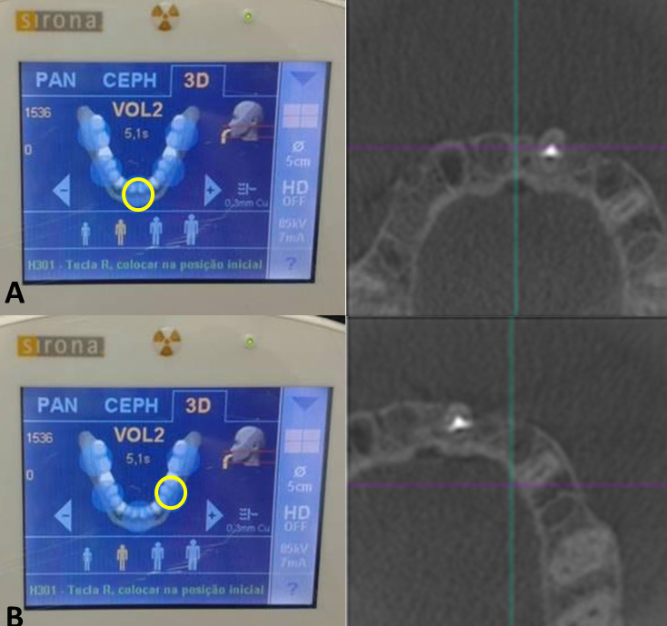
CBCT system pre-set position of teeth within the FOV: central and peripheral.
(2) CBCT scanner position within the FOV established by the operator: Four diagonal positions within the FOV were established by dividing the FOV into four equal size quadrants and the object was centered within each quadrant: Q1 – upper left quadrant; Q2 – upper right quadrant, Q3 – lower left quadrant, Q4 – lower right quadrant (Figure 2).
Figure 2.
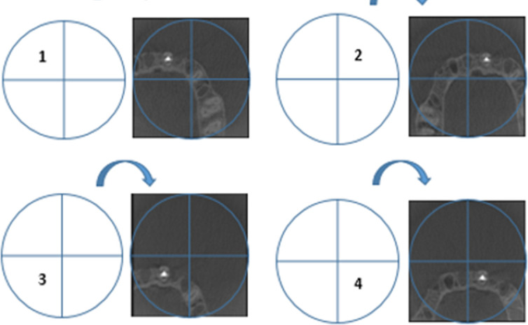
Positioning of teeth within the FOV established by the operator.
A total of 960 CBCT scans [40 teeth (20 sound and 20 fractured) x four exposure protocols (2 FOV sizes and two scanning modes) x six positions within the FOV] were acquired and saved as Digital Imaging and Communications in Medicine (DICOM) files. All scans were coded according to the presence or absence of root fracture, FOV size, position within the FOV, scanning mode and metal post group.
Image assessment
Each DICOM file was read on the scanner’s native software (Sidexis 4, v. 4.1.3, Sirona, York, USA) by two observers, with at least five years of experience on CBCT interpretation. Prior to all sessions, verbal and hands-on instructions and calibration tests were performed. The image assessment was done twice, in two different moments with a two-week interval. Adjustments for zoom, brightness and contrast settings were left to the discretion of each observer. A limit of 20 volumes were evaluated per session.
The assessment of root fracture was done using a 5-point confidence scale for the detection of root fracture: (1) fracture not present; (2) fracture probably not present; (3) uncertain whether fracture was present or not; (4) fracture probably present; and (5) fracture present. For the presence of artefact, a 4-point score scale was used: (0) absent; (1) mild – artefact was present but did not interfere on the diagnosis; (2) moderate – artefact was present and might interfere on the diagnosis; (3) severe – artefact was present and interfered on the diagnosis. When artefact was considered present, the observer would categorize the artefact as: (1) hypodense halos; (2) hypodense lines; and (3) hyperdense lines.
Data analysis
Data were tabulated and analyzed using the Statistical Package for Social Sciences program (IBM SPSS Statistics, v.21, IBM, Chicago, IL, USA). All analyses were conducted considering a 95% confidence level (p < 0.05).
κ intra-observer coefficient reproducibility value for root fracture detection varied from 0.65 to 0.73 and inter observer coefficient from 0.51 to 0.70. κ intra- and inter-observer coefficient for artefact intensity varied from 0.69 to 0.86 and from 0.54 to 0.85, respectively.
The sensitivity, specificity, accuracy, and area under the ROC curve (AUC) values were calculated for the assessment of root fracture and compared by two-way analysis of variance (two-way ANOVA) and Tukey’s test. The presence of artefact and its interference on the detection of root fracture was assessed by descriptive analysis and two-way ANOVA. Comparisons of the artefact characterization among post groups were performed by chi-square and Fisher’s exact tests.
Results
Detection of root fractures
CBCT scanner pre-set position within the FOV
For the NiCr group, the central position presented the highest values of sensitivity, specificity, accuracy and AUC values, and differed from the lateral position (p = 0.03, p = 0.012, p = 0.007 and p = 0.013, respectively). Protocol 4 (HD, 50 × 55) presented higher sensitivity values that differed statistically from protocols 1 (SM, 80 × 80) and 2 (HD, 80 × 80) in the central position within the FOV (p = 0.004). Protocols 3 (SM, 50 × 55) and 4 (HD, 50 × 55) both presented higher sensitivity values that differed statistically from protocols in the lateral position within the FOV (p = 0.027) (Figure 3).
Figure 3.
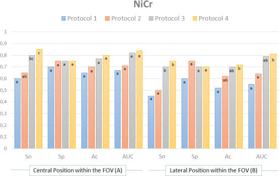
Sensitivity (Sn), specificity (Sp), accuracy (Ac) and area under the curve (AUC) values for the pre-set position within the FOV in each studied protocol for NiCr metal posts.
Protocol 4 (HD, 50 × 55) presented higher accuracy values and differed from protocol 1 (SM, 80 × 80) for NiCr post group in the lateral position within the FOV (p = 0.033). Protocol 4 (HD, 50 × 55) also presented the highest AUC values and differed from protocols 1 (SM, 80 × 80) and 2 (HD, 80 × 80) in the lateral position within the FOV (p = 0.035) (Figure 3).
For the AgPd group, the central position presented the highest values of sensitivity, specificity, accuracy and AUC values, and differed from the lateral position (p = 0.020, p = 0.005, p = 0.010 and p = 0.006, respectively).
Protocols 3 (SM, 50 × 55) and 4 (HD, 50 × 55) both presented higher sensitivity values in the lateral position within the FOV that differed statistically from protocols 1 (SM, 80 × 80) and 2 (HD, 80 × 80) for AgPd (p = 0.039). Protocols 3 (SM, 50 × 55) and 4 (HD, 50 × 55) also presented higher specificity values and differed from protocol 1 (SM, 80 × 80) in the central position within the FOV (p = 0.31) (Figure 4).
Figure 4.
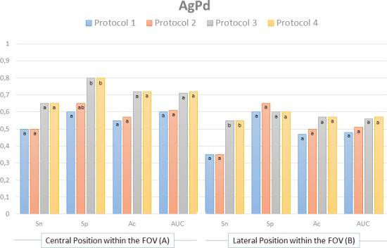
Sensitivity (Sn), specificity (Sp), accuracy (Ac) and area under the curve (AUC) values for the pre-set position within the FOV in each studied protocol for AgPd metal posts.
CBCT scanner position within the FOV established by the operator
Quadrant two presented the best sensitivity, accuracy and AUC values, and differed statistically from the other studied positions within the FOV for NiCr posts (p = 0.001, p = 0.001, p = 0.015).
When assessing NiCr posts, protocols 3 (SM, 50 × 55) and 4 (HD, 50 × 55) presented higher sensitivity values and differed statistically from protocols 1 (SM, 80 × 80) and 2 (HD, 80 × 80) for quadrants 1, 2 and 3 (p = 0.034, p = 0.041, p = 0.023). Protocol 4 (HD, 50 × 55) presented higher sensitivity values and differed from protocol 1 (SM, 80 × 80) and 2 (HD, 80 × 80) for quadrant 4 (p = 0.038). Protocol four also presented higher AUC values and differed from protocol 1 (SM, 80 × 80) for quadrant 3 (p = 0.043) (Figure 5).
Figure 5.
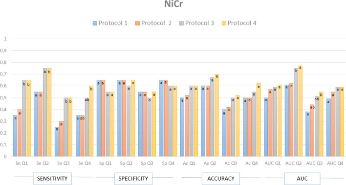
Sensitivity (Sn), specificity (Sp), accuracy (Ac) and area under the curve (AUC) values for the position within the FOV established by the operator for NiCr metal posts.
Quadrant two presented the best sensitivity, specificity, accuracy and AUC values, and differed statistically from the other studied positions within the FOV for AgPd posts (p = 0.002, p = 0.048 p = 0.014, p = 0.028).
Protocols 3 (SM, 50 × 55) and 4 (HD, 50 × 55) presented higher sensitivity values and differed statistically from protocols 1 (SM, 80 × 80) and 2 (HD, 80 × 80) for quadrants 2 and 3, and from protocol 1 (SM, 80 × 80) for quadrant 4 (p = 0.024, p = 0.037, p = 0.026). Protocol 4 (HD, 50 × 55) differed from protocol 1 (SM, 80 × 80) for quadrant 1 (0.033). Additionally, protocols 3 (SM, 50 × 55) and 4 (HD, 50 × 55) presented higher accuracy values and differed from protocol 1 (SM, 80 × 80) for quadrant 3 (p = 0.037) (Figure 6).
Figure 6.
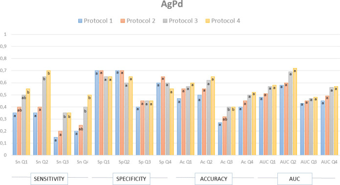
Sensitivity (Sn), specificity (Sp), accuracy (Ac) and area under the curve (AUC) values for the position within the FOV established by the operator for AgPd metal posts.
Artefact assessment
CBCT scanner pre-set position within the FOV
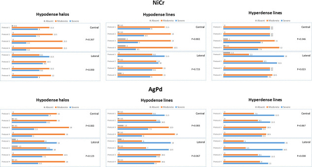
AgPd posts in the lateral position within the FOV and scanned with protocols 1 (SM, 80 × 80) and 2 (HD, 80 × 80) presented higher frequency of artifacts classified as “severe” (65%). On the other hand, NiCr posts in the central position within the FOV and scanned with protocols 3 (SM, 50 × 55) and 4 (HD, 50 × 55) presented higher frequency of artefacts classified as “mild” (20 and 30%).
The presence of severe hyperdense lines decreased in images acquired with protocols 3 and 4 in the lateral position within the FOV for NiCr metal posts (p = 0.023) and AgPd metal posts (p = 0.038) (Figure 7).
Figure 7.
Frequency of artifacts (hypodense halos, hypodense lines and hyperdense lines) for the pre-set position within the FOV in each studied metal post and scanning protocol.
CBCT scanner position within the FOV established by the operator
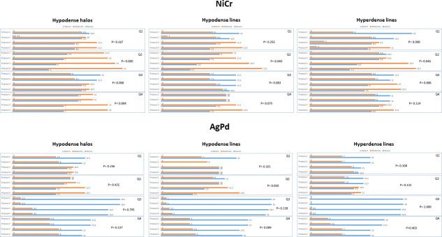
When assessing the studied quadrants within the FOV, AgPd posts, protocols 1 (SM, 80 × 80) and 2 (HD, 80 × 80), quadrants 1 and 3 presented the higher frequencies of artifacts classified as “severe” (80–90% and 90–95%). Quadrant 2, NiCr posts, protocols 3 (SM, 50 × 55) and 4 (HD, 50 × 55) presented higher frequency of artifacts classified as “moderate” (65 and 75%).
For NiCr posts, protocols 3 (SM, 50 × 55) and 4 (HD, 50 × 55) presented reduced frequency of severe hypodense halos, hypodense and hyperdense lines on quadrant 2 (p = 0.001, p = 0.040 and p = 0.046). Protocols 3 (SM, 50 × 55) and 4 (HD, 50 × 55) also differed from protocols 1 (SM, 80 × 80) and 2 (HD, 80 × 80) for hyperdense lines for quadrant 1 (p = 0.001). For AgPd posts, protocol 4 (HD, 50 × 55) presented a lower frequency of severe artifacts compared to protocols 1 (SM, 80 × 80) and 2 (HD, 80 × 80) on quadrant 2 (p = 0.020). Overall, quadrant two presented lower frequency of severe artefacts (Figure 8).
Figure 8.
Frequency of artifacts (hypodense halos, hypodense lines and hyperdense lines) for the position within the FOV established by the operator in each studied metal post and scanning protocol.
Discussion
CBCT scanners have been evolving in order to reduce scanning time, improve image fidelity, minimize patient dose,12,15 and eliminate, or at least reduce, the large number of imaging artifacts that may impair its diagnostic quality.16–19 Metal artefact reduction (MAR) algorithms are available as a post-processing artefact reduction tools, and manufacturers have widely added this feature to recent CBCT scanners available in the market. However, the region of interest should be placed in the center of the FOV for the MAR tool to be effective.20 Even though post-processing tools are useful, technical improvements that allow a reduction in radiation dose while optimizing image quality would provide greater benefits for patients.
Previous studies have shown that variations in exposure parameters may reduce radiation dose while maintaining CBCT image accuracy.21–23 However, tube current (mA) seems to interfere on image quality when reduced to exceptionally low levels.12 In this study, tube current varied from 5mA to 7mA, which are not considered low enough to affect image quality.12 According to Pauwels et al. (2014), by decreasing mA values one can proportionally decrease radiation dose with a fixed tube voltage (kV); however, CBCT scans acquired with low mA and kV may present higher artefact intensity.5
The number of basis projections is another parameter that may influence the exposure dose and it can be directly adjusted depending on the CBCT unit or, in most cases, it is adjusted indirectly by selecting various rotation protocols. It has been reported that the diagnosis of root fractures, root resorptions and periapical bone loss may be kept at acceptable levels even when protocols with a lower number of projections was used.14 In the present study, the number of projections increased from 200 to 500 between SM and HD protocols, which was also followed by an increase in mAs.
Most CBCT units have scanning protocols that were pre-set by the manufacturer in a way that the effective exposure time and/or number of basis projections increase when the operator decreases the mA; therefore, the radiation dose also increases or is maintained at the same level as the high mA protocol. Those pre-set protocols are usually denominated high definition/resolution and standard mode/resolution, varying from manufacturers. Some scanners will indicate the ideal combination of parameters based on patients’ characteristics (age, sex, size), leaving the choice of using the pre-set protocols to the operator. Choosing the exposure, scanning, and imaging protocols is an important step of the CBCT scan acquisition. When the scanner has fixed protocols, it is important to choose the one with the lowest radiation exposure without impairing the diagnosis, following the ALADAIP principal (As Low as Diagnostically Acceptable being Indication-oriented and Patient-specific).24
Choosing the correct FOV according to the diagnostic task also depends on the CBCT scanner used for image acquisition. The CBCT unit used in this study only provided small and medium FOV size options (50 × 55 mm, 80 × 55 mm, and 80 × 80 mm). If the parameters are kept the same, choosing a smaller FOV can lower exposure doses and increase contrast resolution.13 In this study, the smaller FOV size presented the highest sensitivity, specificity, accuracy, and AUC values for the detection of root fracture and the lowest artefact intensity; therefore, one could assume that larger FOVs may impair that diagnostic task.
Although small voxel sizes are indicated for root fracture assessment, some other diagnostic tasks in endodontics may not be jeopardized by scans acquired with larger voxel size – with the benefit of dose reduction.14 The effect of the voxel size on the detection of root fracture may vary depending on the CBCT unit used.25 Although the small voxel size protocol (100 µm) presented a higher accuracy values specially for the low atomic number metal post group, it usually did not differ from the other assessed scanning protocols (160 µm), probably because the difference between the voxel sizes was small. According to Iikubo et al. (2016), scanning modes with small voxel sizes associated with the centralization of the target object within the FOV can reduce fracture-like artifacts.18
The position of the object within the FOV and FOV size may present a higher influence on the detection of root fracture and artefact perception than the studied exposure parameters associated to the scanning modes. According to Nikbin et al (2018), the position of the object within the FOV has greater impact on artefact intensity than the use of MAR tools.26 Based on that, the region of interest should be centered and foremost within the FOV, and a smaller FOV should be chosen when assessing root fracture to increase resolution and avoid exomass artefacts.
Tomographical images with great artefact intensity can lead to low intra- and inter-observer agreement values for fracture detection.9 The present study reached a moderate-to-good intra- and inter observer agreement values, in agreement with previous studies,4,9 which indicates that great artefact intensity produced by high density materials can impair image assessment. Moreover, when the tooth was not centered within the FOV, the accuracy values varied between observers.
CBCT artefacts present different patterns according to the restored tooth and its adjacent structures.18 According to Iikubo et al. (2016),18 the geometric patterns of the CBCT artefact lines induced by intracanal fillings always appear along the long axis of the alveolar bone in an oblique direction (mesiobuccal, mesiolingual, distolingual, or distobuccal) in maxillary central incisors and in the mesiodistal direction in mandibular second premolars, presumably due to beam-hardening effects. Previous studies presented higher sensitivity values for root fractures obliquely oriented than mesiodistally oriented; however, this difference was not significant.27,28 The type of intracanal filling material used to restore the root can also contribute to artefact intensity6,21,29 and, therefore, impairing the detection of root fractures. The sample used in this study consisted of teeth restored with metal posts and, when fractured, there was no separation of the root fragments, what can make fracture detection even harder and lead to low or moderate sensitivity values.
Observers seem to prefer images acquired with high exposure parameters; however, those images may not improve the diagnosis of root fractures. In this study, although the artefacts were less noticeable in images acquired using the HD scanning mode, this protocol did not increase root fracture detection. Smaller FOV sizes and the position of the object of interest within the FOV improved root fracture detection, indicating that low-dose exposure parameters enable root fracture detection, while decreasing patient’s radiation exposure dose. Therefore, exposure parameters should be carefully chosen by the operator based on the specific diagnostic task and patient specificities, in other words, indication-oriented and patient-specific.24
Conclusion
Positioning the object in the centre or closer to the anterior periphery of the FOV and choosing small FOV sizes improves the detection of root fracture and decreases artefact interference. Increasing the number of basis projections while reducing tube current and increasing exposure time does not improve the detection of root fracture, while high-density materials in the root canal impair that diagnostic task.
Contributor Information
Martina Gerlane de Oliveira Pinto, Email: martinnacg@gmail.com.
Saulo L. Sousa Melo, Email: sousamel@ohsu.edu.
Fernanda Clotilde Mariz Suassuna, Email: fernandacosta3@hotmail.com.
Luiz Eduardo Marinho, Email: luizemx@gmail.com.
José Bruno da Silva Leite, Email: brunoleite82@gmail.com.
Andre Ulisses Dantas Batista, Email: andreulisses@yahoo.com.br.
Patrícia Meira Bento, Email: patmeira@uol.com.br.
Daniela Pita Melo, Email: danipita@gmail.com.
REFERENCES
- 1.Scarfe WC, Levin MD, Gane D, Farman AG. Use of cone beam computed tomography in Endodontics. Int J Dent 2009; 2009: 1–20. doi: 10.1155/2009/634567 [DOI] [PMC free article] [PubMed] [Google Scholar]
- 2.Wang Y, Zheng Q-hua, Zhou X-dong, Tang L, Wang Q, Zheng G-ning, et al. Evaluation of the root and canal morphology of mandibular first permanent molars in a Western Chinese population by cone-beam computed tomography. J Endod 2010; 36: 1786–9. doi: 10.1016/j.joen.2010.08.016 [DOI] [PubMed] [Google Scholar]
- 3.Venskutonis T, Plotino G, Juodzbalys G, Mickeviciene L. Cbct imaging in the management of endodontic problems. J Endod 2014; 40: 1895–901. [DOI] [PubMed] [Google Scholar]
- 4.Bechara B, Alex McMahan C, Moore WS, Noujeim M, Teixeira FB, Geha H. Cone beam CT scans with and without artefact reduction in root fracture detection of endodontically treated teeth. Dentomaxillofac Radiol 2013; 42: 20120245–6. doi: 10.1259/dmfr.20120245 [DOI] [PMC free article] [PubMed] [Google Scholar]
- 5.Schulze R, Heil U, Gross D, Bruellmann DD, Dranischnikow E, Schwanecke U, et al. Artefacts in CBCT: a review. Dentomaxillofac Radiol 2011; 40: 265–73. doi: 10.1259/dmfr/30642039 [DOI] [PMC free article] [PubMed] [Google Scholar]
- 6.Lira de Farias Freitas AP, Cavalcanti YW, Costa FCM, Peixoto LR, Maia AMA, Rovaris K, et al. assessment of artefacts produced by metal posts on CBCT images. Int Endod J 2019; 52: 223–36. [DOI] [PubMed] [Google Scholar]
- 7.Hassan B, Metska ME, Ozok AR, van der Stelt P, Wesselink PR. Detection of vertical root fractures in endodontically treated teeth by a cone beam computed tomography scan. J Endod 2009; 35: 719–22. doi: 10.1016/j.joen.2009.01.022 [DOI] [PubMed] [Google Scholar]
- 8.Hassan B, Metska ME, Ozok AR, van der Stelt P, Wesselink PR. Comparison of five cone beam computed tomography systems for the detection of vertical root fractures. J Endod 2010; 36: 126–9. doi: 10.1016/j.joen.2009.09.013 [DOI] [PubMed] [Google Scholar]
- 9.Patel S, Brady E, Wilson R, Brown J, Mannocci F. The detection of vertical root fractures in root filled teeth with periapical radiographs and CBCT scans. Int Endod J 2013; 46: 1140–52. doi: 10.1111/iej.12109 [DOI] [PubMed] [Google Scholar]
- 10.Shokri A, Jamalpour MR, Khavid A, Mohseni Z, Sadeghi M. Effect of exposure parameters of cone beam computed tomography on metal artifact reduction around the dental implants in various bone densities. BMC Med Imaging 2019; 19: 1–10. doi: 10.1186/s12880-019-0334-4 [DOI] [PMC free article] [PubMed] [Google Scholar]
- 11.Safi Y, Hosseinpour S, Aziz A, Bamedi M, Malekashtari M, Vasegh Z. Effect of Amperage and field of view on detection of vertical root fracture in teeth with Intracanal posts. Iran Endod J 2016; 11: 202–7. doi: 10.7508/iej.2016.03.011 [DOI] [PMC free article] [PubMed] [Google Scholar]
- 12.Jones D, Mannocci F, Andiappan M, Brown J, Patel S. The effect of alteration of the exposure parameters of a cone-beam computed tomographic scan on the diagnosis of simulated horizontal root fractures. J Endod 2015; 41: 520–5. doi: 10.1016/j.joen.2014.11.022 [DOI] [PubMed] [Google Scholar]
- 13.de Oliveira Pinto MG, Sousa Melo SL, Cavalcanti YW, de Lima ED, Bento PM, de Melo DP. Influence of tooth position within the field of view on the intensity of cone-beam computed tomographic imaging artifacts when assessing teeth restored with various intracanal materials. Imaging Sci Dent 2020; 50: 141–51. doi: 10.5624/isd.2020.50.2.141 [DOI] [PMC free article] [PubMed] [Google Scholar]
- 14.Yeung AWK, Jacobs R, Bornstein MM. Novel low-dose protocols using cone beam computed tomography in dental medicine: a review focusing on indications, limitations, and future possibilities. Clin Oral Investig 2019; 23: 2573–81. doi: 10.1007/s00784-019-02907-y [DOI] [PubMed] [Google Scholar]
- 15.Özer SY. Detection of vertical root fractures by using cone beam computed tomography with variable voxel sizes in an in vitro model. J Endod 2011; 37: 75–9. doi: 10.1016/j.joen.2010.04.021 [DOI] [PubMed] [Google Scholar]
- 16.Benic GI, Sancho-Puchades M, Jung RE, Deyhle H, Hämmerle CHF. In vitro assessment of artifacts induced by titanium dental implants in cone beam computed tomography. Clin Oral Implants Res 2013; 24: 378–83. doi: 10.1111/clr.12048 [DOI] [PubMed] [Google Scholar]
- 17.Pauwels R, Stamatakis H, Bosmans H, Bogaerts R, Jacobs R, Horner K, et al. Quantification of metal artifacts on cone beam computed tomography images. Clin Oral Implants Res 2013; 24 Suppl A100: 94–9. doi: 10.1111/j.1600-0501.2011.02382.x [DOI] [PubMed] [Google Scholar]
- 18.Iikubo M, Nishioka T, Okura S, Kobayashi K, Sano T, Katsumata A, et al. Influence of voxel size and scan field of view on fracture-like artifacts from gutta-percha obturated endodontically treated teeth on cone-beam computed tomography images. Oral Surg Oral Med Oral Pathol Oral Radiol 2016; 122: 631–7. doi: 10.1016/j.oooo.2016.07.014 [DOI] [PubMed] [Google Scholar]
- 19.Codari M, de Faria Vasconcelos K, Ferreira Pinheiro Nicolielo L, Haiter Neto F, Jacobs R. Quantitative evaluation of metal artifacts using different CBCT devices, high-density materials and field of views. Clin Oral Implants Res 2017; 28: 1509–14. doi: 10.1111/clr.13019 [DOI] [PubMed] [Google Scholar]
- 20.Queiroz PM, Santaella GM, da Paz TDJ, Freitas DQ. Evaluation of a metal artefact reduction tool on different positions of a metal object in the FOV. Dentomaxillofac Radiol 2017; 46: 20160366–4. doi: 10.1259/dmfr.20160366 [DOI] [PMC free article] [PubMed] [Google Scholar]
- 21.Pinto MGO, Rabelo KA, Sousa Melo SL, Campos PSF, Oliveira LSAF, Bento PM, et al. Influence of exposure parameters on the detection of simulated root fractures in the presence of various intracanal materials. Int Endod J 2017; 50: 586–94. doi: 10.1111/iej.12655 [DOI] [PubMed] [Google Scholar]
- 22.Rabelo KA, Cavalcanti YW, de Oliveira Pinto MG, Sousa Melo SL, Campos PSF, de Andrade Freitas Oliveira LS, et al. Quantitative assessment of image artifacts from root filling materials on CBCT scans made using several exposure parameters. Imaging Sci Dent 2017; 47: 189–97. doi: 10.5624/isd.2017.47.3.189 [DOI] [PMC free article] [PubMed] [Google Scholar]
- 23.Pauwels R, Jacobs R, Singer SR, Mupparapu M. CBCT-based bone quality assessment: are Hounsfield units applicable? Dentomaxillofac Radiol 2015; 44: 20140238–16. doi: 10.1259/dmfr.20140238 [DOI] [PMC free article] [PubMed] [Google Scholar]
- 24.Oenning AC, Pauwels R, Stratis A, De Faria Vasconcelos K, Tijskens E, De Grauwe A, et al. Halve the dose while maintaining image quality in paediatric cone beam CT. Sci Rep 2019; 9: 5521–7. doi: 10.1038/s41598-019-41949-w [DOI] [PMC free article] [PubMed] [Google Scholar]
- 25.Guo XL, Li G, Zheng JQ, Ma RH, Liu FC, Yuan FS, et al. Accuracy of detecting vertical root fractures in non-root filled teeth using cone beam computed tomography: effect of voxel size and fracture width. Int Endod J 2019; 52: 887–98. doi: 10.1111/iej.13076 [DOI] [PubMed] [Google Scholar]
- 26.Nikbin A, Dalili Kajan Z, Taramsari M, Khosravifard N. Effect of object position in the field of view and application of a metal artifact reduction algorithm on the detection of vertical root fractures on cone-beam computed tomography scans: An in vitro study. Imaging Sci Dent 2018; 48: 245–54. doi: 10.5624/isd.2018.48.4.245 [DOI] [PMC free article] [PubMed] [Google Scholar]
- 27.Kambungton J, Janhom A, Prapayasatok S, Pongsiriwet S. Assessment of vertical root fractures using three imaging modalities: cone beam CT, intraoral digital radiography and film. Dentomaxillofac Radiol 2012; 41: 91–5. doi: 10.1259/dmfr/49798768 [DOI] [PMC free article] [PubMed] [Google Scholar]
- 28.Nascimento HAR, Neves FS, de-Azevedo-Vaz SL, Duque TM, Ambrosano GMB, Freitas DQ. Impact of root fillings and posts on the diagnostic ability of three intra-oral digital radiographic systems in detecting vertical root fractures. Int Endod J 2015; 48: 864–71. doi: 10.1111/iej.12382 [DOI] [PubMed] [Google Scholar]
- 29.Diniz de Lima E. Lira de Farias Freitas AP, Suassuna FCM, melo SLS, Bento PM, de melo DP. assessment of cone-beam computed tomographic artifacts from different intracanal materials on bi-rooted teeth. J Endod 2019; 45: 209–13. [DOI] [PubMed] [Google Scholar]


