

Abstract
The staging of the central-chest lymph nodes is a major step in the management of lung-cancer patients. For this purpose, the physician uses a device that integrates videobronchoscopy and an endobronchial ultrasound (EBUS) probe. To biopsy a lymph node, the physician first uses videobronchoscopy to navigate through the airways and then invokes EBUS to localize and biopsy the node. Unfortunately, this process proves difficult for many physicians, with the choice of biopsy site found by trial and error. We present a complete image-guided EBUS bronchoscopy system tailored to lymph-node staging. The system accepts a patient’s 3D chest CT scan, an optional PET scan, and the EBUS bronchoscope’s video sources as inputs. System workflow follows two phases: (1) procedure planning and (2) image-guided EBUS bronchoscopy. Procedure planning derives airway guidance routes that facilitate optimal EBUS scanning and nodal biopsy. During the live procedure, the system’s graphical display suggests a series of device maneuvers to perform and provides multimodal visual cues for locating suitable biopsy sites. To this end, the system exploits data fusion to drive a multimodal virtual bronchoscope and other visualization tools that lead the physician through the process of device navigation and localization. A retrospective lung-cancer patient study and follow-on prospective patient study, performed within the standard clinical workflow, demonstrate the system’s feasibility and functionality. For the prospective study, 60/60 selected lymph nodes (100%) were correctly localized using the system, and 30/33 biopsied nodes (91%) gave adequate tissue samples. Also, the mean procedure time including all user interactions was 6 min 43 s All of these measures improve upon benchmarks reported for other state-of-the-art systems and current practice. Overall, the system enabled safe, efficient EBUS-based localization and biopsy of lymph nodes.
Keywords: Bronchoscopy, Lung cancer staging, Endobronchial ultrasound, Image-guided surgery systems, Multimodal imaging, Lymph nodes
1. Introduction
Accurate staging of the chest lymph nodes at the time of diagnosis is critical for follow-on management of lung cancer patients [1]. In particular, lung-cancer stage indicates the extent and possible spread of the disease, which in turn dictates the subsequent surgical or therapeutic options to follow [2]. Since lung cancer is the most common cause of cancer death, it is vital to ascertain proper disease stage [3].
To stage lung cancer, physicians first draw on radiologic imaging, including three-dimensional (3D) chest computed tomography CT and positron emission tomography (PET), to identify suspicious lymph nodes [2,4]. Next, based on the imaging findings, the physician uses a linear endobronchial ultrasound (EBUS) bronchoscope to collect biopsy samples of each lymph node via transbronchial needle aspiration (TBNA) [4–8]. While expert physicians can achieve a high EBUS TBNA biopsy success rate, overall physician skill in using EBUS varies considerably, with biopsy success rates as low as 50% reported [8–11]. The fundamental limitation here is the lack of a suitable means for guiding the procedure. We propose a complete image-guided EBUS bronchoscopy system tailored to central-chest lymph node staging.
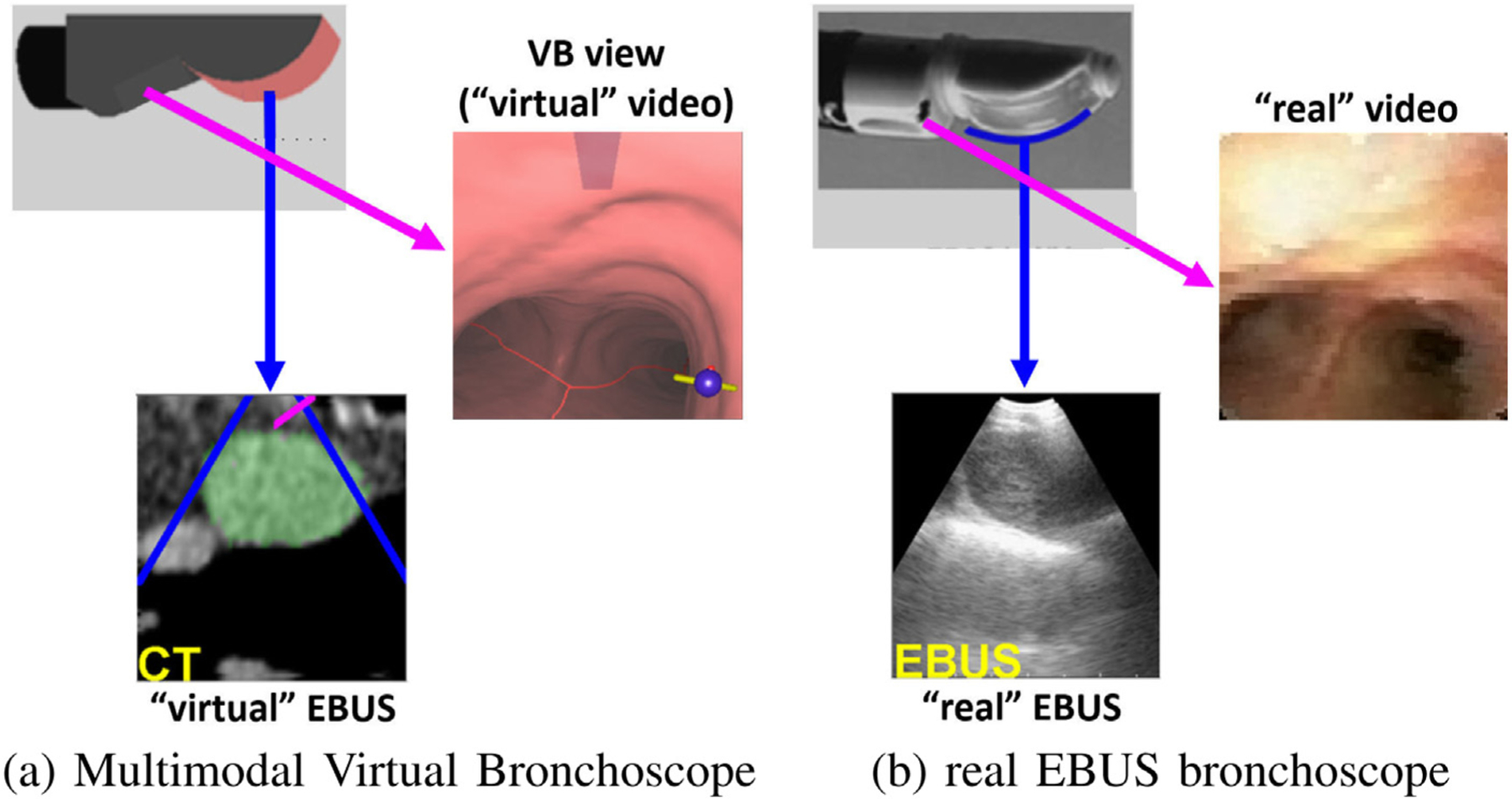
As Fig. 1a illustrates, an EBUS bronchoscope is an integrated multimodal device that combines videobronchoscopy and convex-probe EBUS into a single unit [5,6]. The videobronchoscope gives video of airway endoluminal (interior) structure, while complementary EBUS gives fan-beam-shaped 2D cross-sectional images of the extraluminal anatomy adjacent to the airway walls probed by EBUS (Figs. 1bc). Because lymph nodes lie hidden behind the airway walls, they cannot be seen by videobronchoscopy. They can, however, be seen by EBUS as dark masses. Thus, EBUS gives essential in vivo verification of a node’s extraluminal location.
Fig. 1.
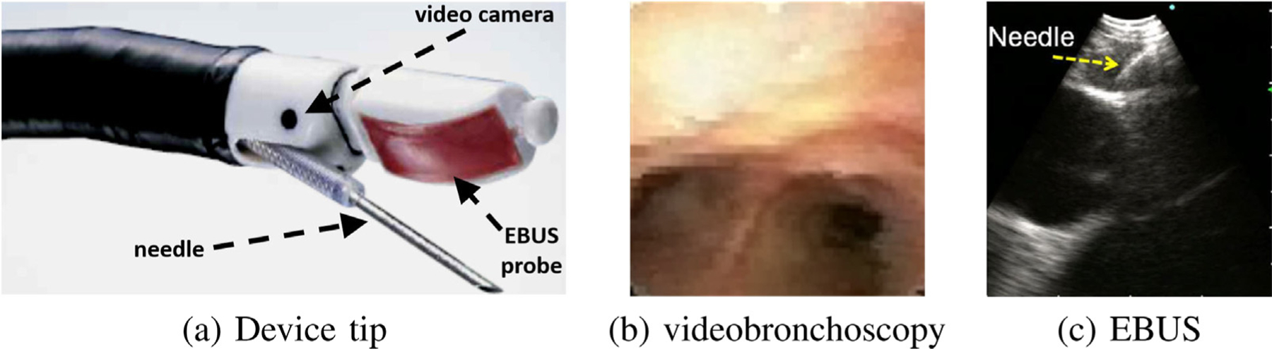
Linear EBUS bronchoscope. (a) device tip; (b) videobronchoscope view; (c) EBUS view illustrating TBNA needle piercing a localized lymph node. Note: views (b) and (c) are not taken from the same airway location.
In current practice, the physician relies on two skills to biopsy a lymph node: (1) anatomical knowledge; and (2) ability to translate 3D nodal locations pre-identified on the imaging scans (CT and/or PET) to what they see with the EBUS bronchoscope. Thus, during bronchoscopy, the physician must first mentally infer how to navigate the device close to a given node. Next, upon reaching what they believe is the node’s general vicinity, they then must localize an extraluminal biopsy site by a trial-and-error EBUS sweep of the airway walls. This can be challenging, given the small size of most lymph nodes (≥10 mm long-axis length), the complex 360 ° cylindrical span of the airway walls, and the essentially blind nature of EBUS-based localization. Also, since EBUS has a very different geometric viewpoint from the other data sources (CT, PET, videobronchoscopy), the physician is forced to mentally correlate live EBUS observations to cues seen in the other data sources. Thus, accurate localization – crucial for effective safe biopsy – is well known to be problematic [10–12].
On another front, new image-guided bronchoscopy systems have proven to reduce physician skill differences for bronchoscopic navigation through the airways, thereby making navigation a high-success, skill-independent operation [13–16]. Fundamentally, these systems draw on the concept of virtual bronchoscopy [17–19]. In virtual bronchoscopy, a CT-derived virtual bronchoscope (VB), which closely mimics the video views of the “real” bronchoscope, is virtually navigated through the 3D CT scan. The vivid sub-millimeter resolution now common for chest CT makes this possible by enabling detailed visualization of the airways and other chest anatomy.
To use an image-guided bronchoscopy system, a procedure plan, consisting of airway guidance routes leading to each diagnostic region of interest (ROI), is first derived through computer analysis of the patient’s chest CT scan [13,14,20]. Next, during the live procedure, the system depicts VB-based endoluminal views along the ROI’s route that helps the physician maneuver the videobronchoscope to the final airway adjacent to the “real” ROI [13,21,22]. During navigation, some image-guided bronchoscopy systems register the virtual bronchoscope to the real bronchoscope [15,20,23]. In this way, data fusion between an image-based virtual chest space and video-based real chest space can take place to give the physician an “augmented reality” view of the patient’s anatomy during the live procedure (see Fig. 2 later).
Fig. 2.
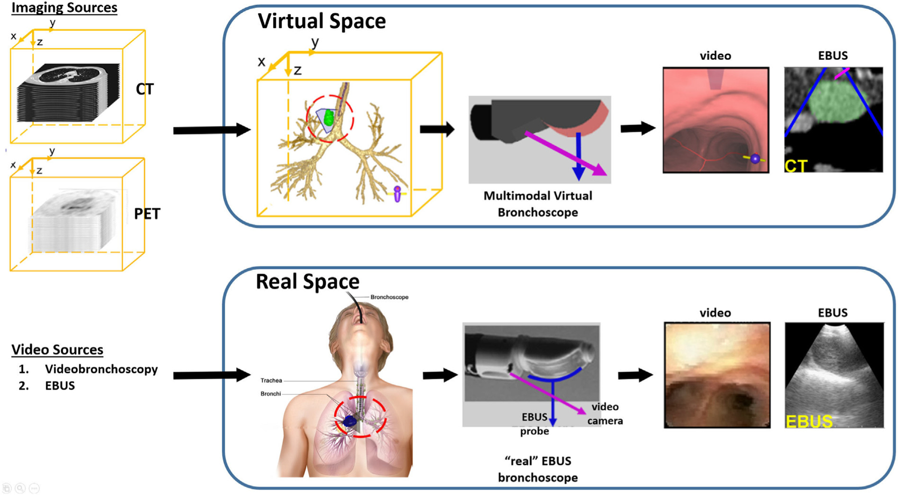
Multimodal data space for our image-guided EBUS bronchoscopy system. The CT scan and optional PET scan delineates the virtual 3D chest space. The videobronchoscopy and EBUS video streams represent manifestations of the real 3D chest space. The two spaces become linked after synchronizing the Multimodal Virtual Bronchoscope and real EBUS bronchoscope sources. The red and blue arrows represent the points of view of the videobronchoscope and EBUS probe, respectively.
Unfortunately, limited progress has been made toward extending image guidance to EBUS localization and nodal staging [24–26]. The system of Sato et al. entails considerable user interaction to preplan sites for invoking EBUS [24]. Also, during the live procedure, the system offers no virtual-to-real EBUS registration to help confirm device placement and biopsy sample potential. Sorger et al. proposed a commendable image-guided system that draws upon electromagnetic navigation hardware and an extra sensor attached to the EBUS bronchoscope [25,26]. Yet, the system does not provide a plan giving guidance for optimal EBUS placement nor register the pre-operative CT data to the live EBUS probe view. It also adds the well-known issues arising from using electromagnetic technology (extra device cost, susceptibility to patient motion) [13].
On a related front, two groups have applied virtual bronchoscopy to the fundamentally different problem of peripheral lung nodule diagnosis, which draws on two separate devices: a standard videobronchoscope and a radial-probe EBUS [27,28]. The physician uses VB to navigate the videobronchoscope close to the nodule and then inserts the radial-probe EBUS into the videobronchoscope’s working channel to give 360 ° views of the extraluminal airway structure. While radial-probe EBUS is not designed for central chest nodal staging and presents a very different guidance scenario having unique guidance challenges (separate devices, requires probe removal before biopsy, very different imaging scenario), these works do motivate work in the central airways.
Our proposed custom system fits within the live clinical workflow to enable image-guided EBUS bronchoscopy for nodal biopsy. The system offers image guidance for both videobronchoscopic navigation and EBUS localization. As part of the guidance strategy, the system extends the standard virtual bronchoscope to an expanded multimodal virtual bronchoscope. Specifically, the multimodal virtual bronchoscope integrates an image-based virtual EBUS probe in tandem with the standard virtual bronchoscope. In addition, custom graphical display tools, facilitating data fusion and EBUS registration, give enhanced multimodal visualization of candidate biopsy sites. To develop the system prototype, we first performed retrospective laboratory studies. We then completed a pilot prospective patient study, conducted within the standard real-time clinical workflow, to validate the system.
Section 2 describes our system. Section 3 describes the patient studies performed to develop and validate the system. Finally, Section 3 offers concluding comments.
2. Methods
Section 2.1 first gives a top-level system overview. Next, Sections 2.2 and 2.3 describe the complete two-phase workflow for deploying the system. Finally, Section 2.4 discusses system implementation.
2.1. System overview
The system accepts as its first input a patient’s high-resolution 3D chest CT scan, as is generally used by new image-guided bronchoscopy systems [14]. The system can also draw on an optional 3D PET scan as a second imaging source, if available, which supplies functional information on suspect cancerous nodes. The PET scan comes from a lower-resolution whole-body PET/CT study often prescribed for lung cancer patients [2,29]. During the live procedure, the system takes as additional inputs the EBUS bronchoscope’s videobronchoscopy and EBUS video streams. We assume that the physician uses the Olympus BF-UC180F or BF-UC190F linear EBUS bronchoscopes, the de facto standard devices used for EBUS TBNA nodal staging [5,6].
Fundamentally, the system synergistically ties all data sources together – the 3D CT and PET imaging scans and the video streams of the EBUS bronchoscope – to facilitate the complete lymph-node staging process. To do this, the system operates within two inter-related multimodal data spaces representing the physical space of the patient’s chest (Fig. 2) [23]:
A virtual space, derived from the radiologic imaging sources, constitutes a virtual copy of the patient’s anatomy and gives the necessary basis for procedure planning and image-guided EBUS bronchoscopy.
A real space, manifested by the EBUS bronchoscope’s two video streams, captures information gathered during the live surgical procedure.
Following the standard EBUS TBNA protocol for lymph node staging, system workflow proceeds in two phases:
Procedure Planning, occurring off-line, produces a plan that drives the subsequent guided procedure.
- Image-Guided EBUS Bronchoscopy, occurring in the surgical suite, goes as follows for each lymph node:
- Navigation: Using videobronchoscopy, the physician navigates the device through the airways close to the expected node location.
- Localization: The physician localizes the node by pushing the EBUS probe against the airway wall. They then biopsy the node — the EBUS view will show the needle piercing the node; e.g., Fig. 1c.
2.2. Procedure planning
For Procedure Planning, computer-based image processing methods first uses the patient’s CT scan to extract a chest model consisting of [20,30–35]: (1) the airway tree lumen and associated endoluminal surfaces; (2) airway-tree centerlines; (3) major vasculature, including the aorta, pulmonary artery, superior vena cava, and azygos vein; and (4) thoracic cavity, which encompasses all pertinent chest anatomy and central-chest lymph nodes. Next, we apply the semi-automatic live wire or related interactive tools to the CT and/or PET scan to define ROIs for target lymph nodes [36,37]. The PET and its associated lymph node ROIs are then mapped into the chest CT’s 3D space via deformable registration to give a fused CT-PET volume [35,38]. For the next step, airway guidance routes that enable optimal EBUS-TBNA biopsy are computed for each lymph node. The optimization includes constraints imposed by the chest anatomy, as seen in CT, and the known EBUS bronchoscope device specifications [12]. Finally, for each airway guidance route, a series of device maneuvers that instruct the physician how to move the device along the route are derived at key transitional jump points [39]. The final procedure plan includes the chest model, lymph node ROIs, and airway guidance routes. Fig. 3 gives a block diagram for this complete process. All operations above draw on methods validated previously in numerous human studies [12,20,30–39].
Fig. 3.
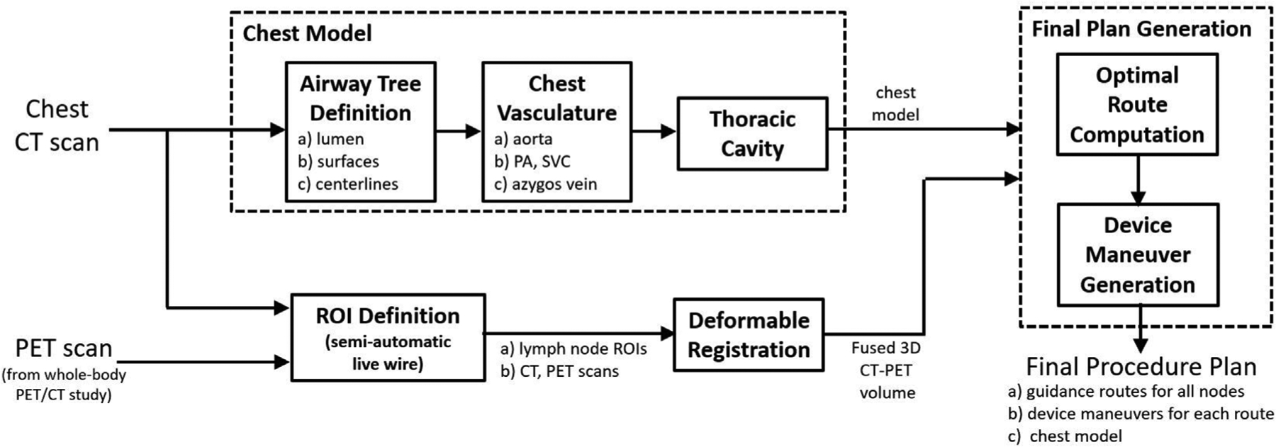
Block diagram for Procedure Planning.
We illustrate procedure planning by way of an example. For a lung-cancer patient exhibiting a PET-avid station 10L lymph node, a chest radiologist first identified the node on the patient’s PET/CT study. We then derived the procedure plan for the target node using a separate high-resolution chest CT. As shown later in Section 2.3, we also performed deformable registration and fusion of the CT and PET scans. Fig. 4 depicts the procedure plan for this lymph node, presented as a one-page summary report. The report depicts a series of CT-based VB views at the derived jump points (1a, 1b, …, 2b) along the airway guidance route. A 3D Surface Tool gives a global view of the airway tree, guidance route, and lymph node. For each jump point, the VB view indicates the designated device maneuver to perform to reach the next jump point. In all views, the blue line denotes the airway guidance route, green regions denote the target lymph node, and red regions indicate occluding major vessels to avoid during needle biopsy.
Fig. 4.
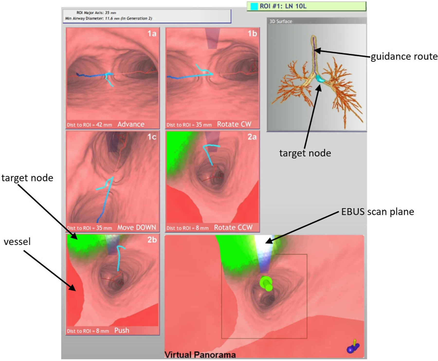
Example procedure plan for a lung-cancer patient exhibiting a PET-avid station 10L lymph node (case 21405-139). Details for imaging sources: chest CT collected with a Siemens Sensation-40 scanner, axial-plane resolution Δx = Δy = 0.8 mm, Δz = 0.5 mm, volume dimensions = 512 × 512 × 667; PET/CT study collected with a Philips TrueFlight integrated scanner, with PET scan details: axial-plane resolution Δx = Δy = 4 mm, section thickness Δz = 3 mm, volume dimensions = 144 × 144 × 312; and CT scan details: Δx = Δy = 0.9 mm, Δz = 3 mm, volume dimensions = 512 × 512 × 312. The lymph node ROI had the following characteristics: node major- and minor-axes lengths = 35 mm and 11.6 mm, respectively; PET volume = 3.4 cm3; SUVmin = 2.7, SUVmax = 7.3, SUVmean = 4.6; CT volume = 3.0 cm3.
Three maneuvers are possible at each jump point:
Advance/Move the device UP or DOWN
Rotate the device CW (clockwise) or CCW (counterclockwise)
Push the EBUS probe against the airway wall
The derived maneuvers take into account the physician’s ability to manipulate the device in accordance with standard bronchoscopy training and manual dexterity [39–41]. For example, “Move DOWN” tells the physician to flex the device down and move forward into the lower visible successive airway, while “Rotate CW” tells the physician to hold the device stationary and rotate it clockwise. For EBUS TBNA, the final maneuver combination always entails a “Rotate” and “Push” to prepare for EBUS scanning. This combination is derived such that it positions the device at the optimal biopsy site. Thus, if it is performed properly, it will enable the physician to immediately see the lymph node in the EBUS view.
A Virtual Panorama viewer, which gives an expanded field-of-view (FOV) VB view adapted to EBUS bronchoscopy, concludes the report. For the report, the Virtual Panorama highlights the final airway route destination by a large green arrow — i.e., the optimal EBUS TBNA site. By convention in this viewer and other viewers, green regions denote the ROI, while red regions denote the major vasculature, which signal “obstacles” to avoid when performing needle biopsy.
Of special note is the transparent blue rectangular icon superim-posed in the upper middle portions of later VB views and the Virtual Panorama. This icon corresponds to the EBUS probe’s forward-looking scan plane. It is in the same position as the real EBUS transducer’s scan plan relative to the real device’s video camera. The icon only appears when the EBUS probe comes into range of the target ROI; i.e., <40 mm from the final destination. (We will refer to the physical EBUS bronchoscope as the “real device”, and the computer-generated EBUS bronchoscope as the “virtual device.) Note that while the EBUS scan plane is in range for VB views 1b through 2a in Fig. 4, it does not yet intersect the green ROI. But as the EBUS bronchoscope moves closer to the ROI, the EBUS scan plane begins to intersect the ROI and the icon correspondingly gets brighter, as shown by VB view 2b and the Virtual Panorama. This alerts the physician that the device is approaching viable needle biopsy sites. The final Virtual Panorama view depicts the situation at the optimal biopsy site — the “white hot” icon color indicates that the EBUS probe will maximally intersect the ROI when it is pushed against the airway wall.
A dynamic movie version of the procedure plan can also be previewed on a portable tablet PC. This gives the ability to perform a “virtual” rehearsal of the procedure, prior to the live real procedure, similar to our previous efforts for CT-only image-guided bronchoscope navigation [42].
2.3. Image-Guided EBUS Bronchoscopy
For Image-Guided EBUS Bronchoscopy, the system interfaces to the bronchoscopy suite hardware to tap off the EBUS bronchoscope’s video outputs. To perform image-guided EBUS TBNA for each target lymph node, the physician follows the system display’s guidance instructions and visual cues to maneuver the EBUS bronchoscope toward the node. In particular, with reference to Fig. 2, the physician moves the real EBUS bronchoscope through the patient’s airways (real chest space) in such a way as to mimic the maneuvers of a virtual EBUS bronchoscope moving through virtual chest space. This entails following the depicted guidance route. At each jump point along the route, the physician maneuvers the real device as instructed so that the real device’s position synchronizes with the virtual device’s position, thereby aligning the two spaces. The system then cycles to the next jump point to suggest the next guidance maneuver for moving the real device (e.g., advance, rotate, push the EBUS probe) and when to switch from videobronchoscopic navigation to EBUS localization.
During the live procedure, the system display presents several visualization tools. These include the aforementioned 3D Surface Tool and Virtual Panorama, along with the following:
Multimodal Virtual Bronchoscope — Mimics both components of the real EBUS bronchoscope (Fig. 5a). The tool’s virtual videobronchoscope simulates the real device’s videobronchoscopy camera via the usual CT-derived virtual bronchoscope (VB view), as done in existing image-guided bronchoscopy systems. In addition, a new virtual EBUS probe, which produces a CT-based virtual EBUS view, simulates 2D fan-shaped EBUS views mimicking the scan plane of the real EBUS probe.
EBUS Bronchoscope viewer — Presents the dual video streams of the real EBUS bronchoscope (Fig. 5b).
Coronal Fused CT-PET Slicer Tool — Depicts 2D coronal slice views of the fused 3D CT-PET volume. Viewer cross-hairs indicate the system’s current 3D global position within the chest, similar to the global view offered by the 3D Surface Tool, while red structures indicate the PET response. (The PET standard uptake value [SUV] scale is also shown.)
Fig. 5.
Comparison of the data sources provided by the Multimodal Virtual Bronchoscope and real EBUS bronchoscope. The figure depicts registered pairs of video views and EBUS views (video and EBUS not at the same site). As in Fig. 2, the red and blue arrows denote the points of view of the video and EBUS views, respectively. For the virtual EBUS view, the blue lines delineate the EBUS FOV, while the red line corresponds to the needle port (cf. Fig. 1d).
As Fig. 6 and others to follow show, the Multimodal Virtual Bronchoscope and EBUS Bronchoscope viewer sit side-by-side on the system display and serve as the system’s primary guidance backbone. With this display, the physician can perceive the relative states of the EBUS bronchoscope in both the virtual guidance space and real surgical space simultaneously.
Fig. 6.
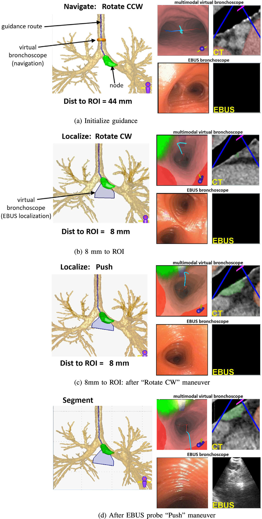
Guidance for a lung-cancer patient exhibiting a PET-avid station 10L lymph node (case 21405-139).
We design the Multimodal Virtual Bronchoscope’s video camera and EBUS probe to comply with the known geometry and specifications of the Olympus EBUS bronchoscope (Fig. 1) [12]. In addition, we apply barrel distortion correction to both the real and virtual videobronchoscope views, as done in many image-guided bronchoscopy systems [43, 44]. Thus, both components are at 3D orientations identical to the configuration of the real EBUS bronchoscope and produce views having FOVs identical to the real device. In this way, multimodal registration of both views (video and EBUS) and spaces becomes feasible during guided bronchoscopy [23,45]. Regarding the virtual EBUS display, the blue lines demarcate the real EBUS’s fan-shaped FOV, while the red line indicates the biopsy needle direction.
We now detail the guidance process for the station 10L lymph node example of Fig. 4. Fig. 6 shows a step-by-step view of the system display during the live guided procedure. For all system viewers, the blue line denotes the pre-computed airway guidance route, the green ROI denotes the target lymph node, and red regions indicate obstructing vessels. The current guidance position, as given by the Multimodal Virtual Bronchoscope’s current position, is depicted as an orange can-shaped icon during navigation and a blue fan-shaped icon during localization. All viewers are synchronized to the same 3D location, viewing direction, and up vector as the procedure progresses. (We omit a few viewers for brevity in Fig. 6.)
The live procedure begins when the physician positions the real device in the trachea near the location depicted by the Multimodal Virtual Bronchoscope (Fig. 6a). The system indicates that the physician should next perform a ‘Rotate CCW” maneuver. In general, the physician is not expected to synchronize the real device’s position “exactly” to the suggested VB view’s position. We do, however, expect the physician to cooperate with the sequential flow of the guidance. The next maneuver for this guidance route is “Move UP” (not shown), whereby the physician is instructed to move the bronchoscope up and forward into the airway.
As the procedure progresses, important guidance cues facilitating EBUS localization begin to appear when the virtual device’s EBUS probe comes within range of the target ROI (<40 mm). Fig. 6b–d depict these cues:
A blue fan-shaped icon assumes the role of the orange Multimodal Virtual Bronchoscope icon in the Airway Tree Viewer. It gives the position of the virtual EBUS’s 2D fan-shaped scan plane within 3D space.
The extraluminal target node appears in the Multimodal Virtual Bronchoscope, with differing shades of green indicating different possible biopsy tissue sample sizes. Fig. 7 shows how this feature assists in selecting effective biopsy sites [12]. (Existing image-guided bronchoscopy systems only present views where all visible ROI points appear with the same brightness [13,15, 23].) Also, nearby obstructing vessels appear in red.
The blue rectangular icon for the EBUS probe’s forward-looking scan plane appears in VB views, as in Fig. 4 report. Notably, Fig. 6b makes it clear that the EBUS scan plane does not yet intersect the green ROI.
Fig. 7.
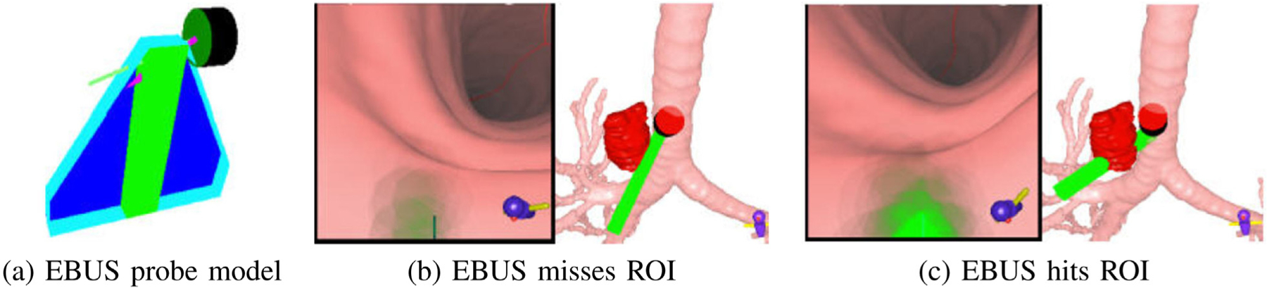
Visualization of ROI tissue-sample size [12]. (a) EBUS probe model, including fan-shaped EBUS scan plane and needle. (b) VB view and 3D Surface Tool showing EBUS probe (green) missing ROI (red). (c) EBUS probe hits ROI.
Continuing, the final rotate/push maneuver combination is now prescribed (Fig. 6bc), with the goal of accurately localizing the target lymph node. It is during this combination that the switch from videobronchoscopic navigation to EBUS localization occurs. In practice, our system previews the final rotate/push maneuvers as a dynamic movie that shows virtual device rotation followed by a virtual EBUS probe push against the airway wall. Following this preview, the physician performs the two maneuvers in quick succession.
Figs. 6c and 8 depict the system state after the physician completes the “Rotate CW” maneuver. The system now suggests the “Push” maneuver. Because accurate node localization is crucial for identifying effective biopsy sites, the Virtual Panorama gives a telling expanded VB view that more fully shows the relationships between the EBUS probe, target ROI, and obstacles before invoking EBUS via the “Push” maneuver (Fig. 8); in addition, the EBUS Camera depicts a related expanded VB view from the virtual EBUS probe’s vantage point (light blue rectangle) and orthogonal to the Virtual EBUS view. These views clearly give a fuller understanding of how the EBUS probe overlaps the ROI relative to possible needle puncture sites and adjacent obstructing vessels. The online supplement gives an illustrative video of system operation at this point.
Fig. 8.
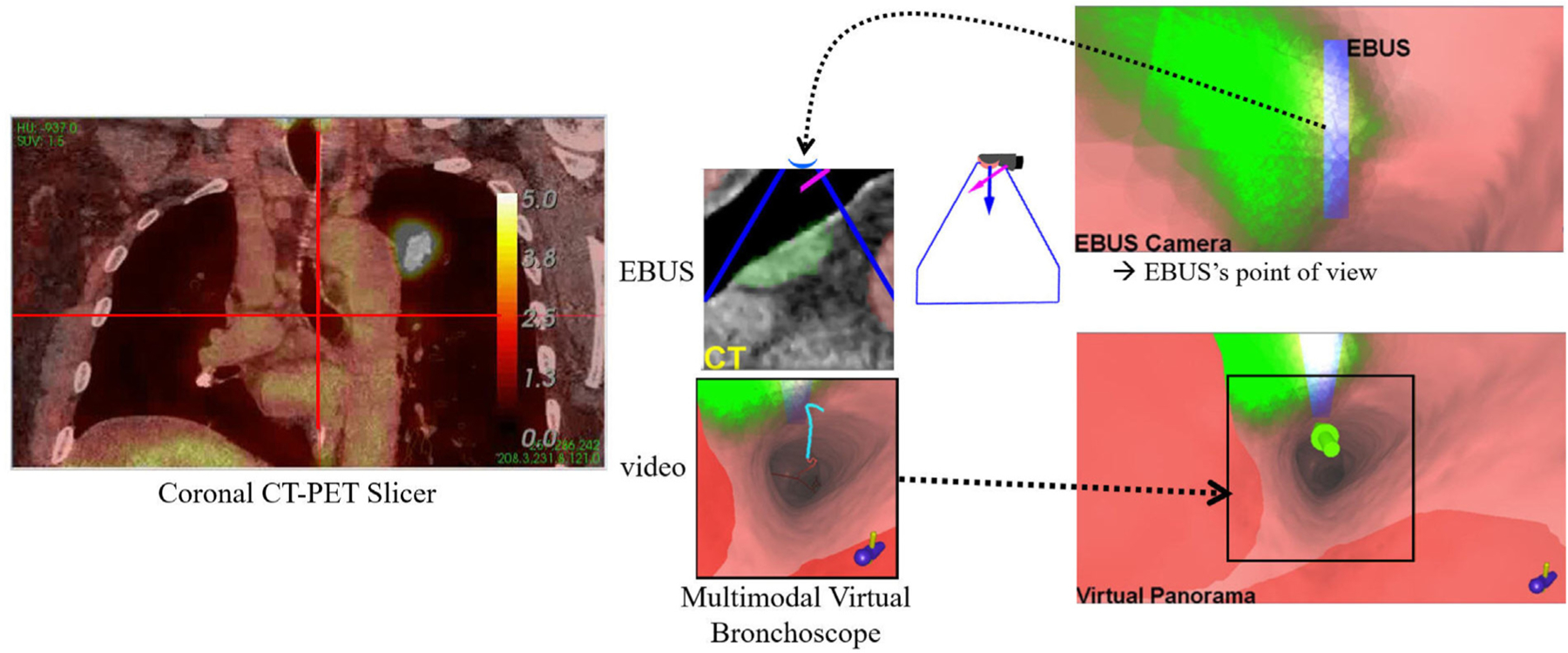
Supplemental views for a station 10L lymph node at the same location as Fig. 6c after the “Rotate CW” maneuver.
Up until now, the physician has relied on videobronchoscopy to perform the procedure. Hence, the real EBUS views have been blank, as Figs. 6a–c show. Fig. 6d illustrates system state after the EBUS push — clearly, the real EBUS view indicates that the physician has immediately hit the target lymph node, without the usual guesswork encountered in standard EBUS practice [11]. The Multimodal Virtual Bronchoscope has now reached the preplanned destination for optimal EBUS ROI localization in virtual space. Specifically, the VB view shows the EBUS probe’s scan plane intersecting the bulk of the node, as indicated by the blue rectangle now appearing white. This suggests that the node is accessible to both the EBUS transducer and biopsy needle. Furthermore, the corresponding virtual EBUS view clearly shows the ROI centered in the EBUS scan plane, away from obstructing vessels.
Yet, it is important to realize that we do not know the real device’s precise position relative to the ROI. We gain this understanding by completing a precise synchronization of the virtual and real device positions. The system accomplishes this synchronization by signaling the “Segment” operation after the EBUS push (Fig. 6d). This alerts the physician to capture a frozen EBUS frame, as shown in Fig. 6d (same as in Fig. 9a). The system now automatically performs two successive operations. First, the EBUS ROI is segmented in the frozen frame using Zang et al.’s segmentation method [46]. Next, the known CT-based ROI is registered to the segmented real EBUS ROI using an automatic multimodal registration method. The method invokes an optimization process that draws upon raw image intensity information and known ROI segmentation knowledge, as discussed in [47]. This precisely synchronizes the EBUS bronchoscope position in both the virtual and real spaces at the frozen real position. Fig. 9 gives results for these operations.
Fig. 9.
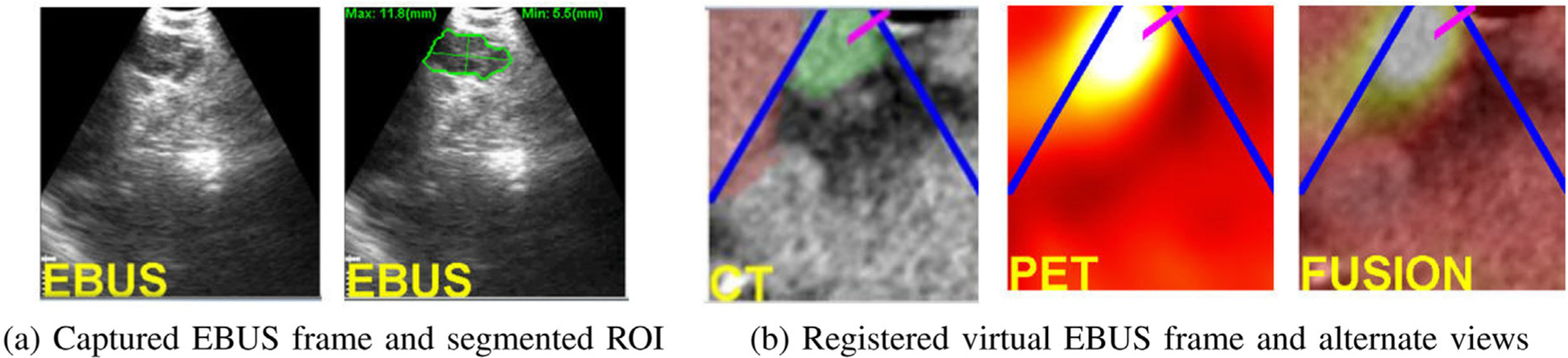
Analysis of a captured EBUS frame for a station 10L node (case 21405-139). (a) Initial captured frame (lymph node clearly appears) and segmented EBUS ROI (green contour). (b) Registered virtual EBUS view and alternate virtual EBUS views using PET and fused CT-PET.
Registration gives two benefits. First, the physician gets confirmation that the live EBUS view corresponds to the desired preplanned CT-based ROI view, while also noting obstacle locations. In addition, related PET and fused CT-PET virtual EBUS views give additional confirmation of this site. Figs. 9 vividly shows that the real EBUS device is positioned at an advantageous location for safe effective biopsy of the target PET-avid node. In this way, the physician achieves successful localization and can now perform the requisite biopsy.
2.4. Implementation details
The complete system resides on a mobile cart that allows interfacing to the bronchoscopy suite hardware. The system software resides on a Dell Precision T5500 PC (64-bit Windows PC, dual 2.8 GHz 6-core Xeon X5660 CPU (12MB shared L3 cache), 24 GB RAM) powered by an nVidia Quadro 4000 2 GB PCIe graphics processing unit (GPU) and a Matrox Vio IA/OA video frame grabber. The main display is a Dell 24-inch 1920 × 1200 wide-screen flat panel monitor. We coded all software using C++ developed in Visual Studio 2015 and drew upon several packages, including Qt, OpenGL, vtk, and the Visualization Library. Because the imaging studies typically consist of ≈0.5 GB of data and the EBUS bronchoscope’s video streams run continuously at 30 frames/sec, we parallelized many data-intensive operations to facilitate smoother user interaction. For this purpose, we drew upon nVidia’s compute-unified device-architecture (CUDA) tools and OpenMP. Also, the alpha blending calculations for displaying tissue sample sizes was accomplished using the GPU [12].
Procedure planning takes on the order of 10–20 min per patient. Semi-automatic ROI definition takes the bulk of the time, with all other automatic operations requiring < 5 min total. This time is similar to the planning time required by our past navigation-only image-guided bronchoscopy studies [20]. As Section 3 later shows, the guidance process, including all user interaction and EBUS analyses, takes on average <1.5 min per lymph node. All pilot studies reported here employed an assisting technician to manage the guidance computer. A capability does exist, though, to perform a procedure autonomously, without technician assistance, as reported in [39].
3. Results
We developed and tested our system using data collected from two series of lung cancer patients. All enrolled patients came through our lung cancer management clinic at the Penn State University’s Milton S. Hershey Medical Center and were scheduled for EBUS bronchoscopy. The subject population included patients whose clinical evaluation required a diagnostic bronchoscopy for evaluation of parenchymal or mediastinal abnormalities. We collected all data under informed consent via two phased IRB-approved study protocols: (1) a retrospective study, to help establish a working system; and (2) a prospective study, to test the prototype system in the clinical setting. Below, we present the results and discussion of these studies.
3.1. Retrospective study
We collected data to help build a functioning system prototype and to make a feasibility study of the completed prototype. 8 patients (4 female, 4 male) with ages ranging from 61 to 82 years were enrolled. Chest CT scans were generated by either a Siemens Somatom Definition Flash or Sensation-40 CT scanner. These scans consisted of 512 × 512 axial-plane sections, with section thickness = 0.75 mm and section spacing = 0.5 mm. The number of sections scan ranged from 570 to 720, and axial-plane resolution Δx = Δy ranged from 0.55 mm to 0.81 mm. In general, chest CT scans having Δx, Δy, and Δz < 1.0 mm offer sufficient resolution for the computation of accurate airway routes and endoluminal surfaces. Throughout our studies, we accepted CT scans collected with or without contrast agent. Four patients also had whole-body PET/CT studies generated by a Philips Gemini Trueflight TOF 16 integrated PET/CT scanner. A PET/CT study consisted of co-registered PET and CT scans, both having lower resolution then the chest CT. Both scans had Δz = 3.0 mm section thickness, with the PET scan having Δx = Δy = 4.0 mm and the CT scan having Δx = Δy < 1.0 mm. Also, the PET scan consisted of 144 × 144 axial-plane sections, while the CT scan consisted of 512 × 512 axial-plane sections.
For all patients, we used the imaging scans to identify suitable ROIs and preplan airway routes leading to each ROI. The planning reports also included interactively derived EBUS sweep regions near each ROI to provide suggested EBUS scan regions. Lymph nodes and/or tumors were derived from a consulting radiologist’s patient report. We also chose vascular structures for some ROIs, as they are easy to reach via bronchoscopy and give clear images in EBUS video. 46 ROIs were predefined for the 8 patients: 21 lymph nodes (station 4, 7 nodes; station 7, 7; stations 10–11, 7), 22 vascular structures (aorta, 4 sites; pulmonary artery, 11; azygos vein, 4; aortopulmonary window, 3), 2 tumors, and 1 mass.
The physician then performed EBUS bronchoscopy using our system’s previewable planning reports as a reference. For each ROI, the physician navigated the device near the ROI and then undertook an EBUS sweep in the airway wall region about the ROI. Because we did not generate device maneuvers for the airway routes used in this feasibility study, the procedure was not guided per se. During the procedure, a technician recorded all EBUS bronchoscopy and computer display video using an Atomos Shogun HDMI/12G-SDI DVR.
These data were then used to devise various system methods for multimodal procedure planning, EBUS segmentation, and virtual-to-real EBUS registration [12,39,47]. (Other methods were derived from our previous navigation-only image-guided bronchoscopy research [20, 23,41].) We also used these data to devise the system’s visualization tools and guidance strategy. This resulted in a working prototype.
We next tested the system prototype in a simulated guidance situation, using the data for the four patients having both chest CTs and PET/CT studies. 14 total ROIs were defined in these cases: 7 lymph nodes (station 4, 3 nodes; station 7, 2; stations 10–11, 2), 6 vessels (3 aorta, 3 pulmonary artery), and 1 mass. We then utilized the image data and previously recorded procedural video to simulate live image-guided EBUS bronchoscopy. For each ROI, we merged bronchoscopic video of a human airway tree phantom, which followed the planned route to the ROI (navigation phase), with video segments from the earlier recorded live procedural video (localization phase). The spliced videos served as the “live” videobronchoscopy and EBUS video streams. Using the system’s guidance, we correctly reached and visually confirmed 14/14 ROIs (100%) jointly with EBUS and the multimodal image sources, thereby establishing system functionality. Figs. 6, 8, and 9 were derived from these studies.
3.2. Prospective study
Given the system prototype, we next conducted a pilot prospective study to assess the system’s functionality, safety, and efficacy in a live setting following the standard real-time clinical workflow. The study involved 13 patients (6 female, 7 male) with ages ranging from 39 to 77 years. For 12 patients, chest CT scans were generated with either the Siemens Somatom Definition Flash or Sensation-40 CT scanners; the remaining case was provided by a Cannon Aquilion Prime scanner. The number of sections ranged from 432 to 728, and the axial-plane resolution Δx = Δy ranged from 0.55 mm to 0.79 mm. Other chest CT details were the same as in the retrospective study. 10 patients also had whole-body PET/CT studies, with 9 produced by the aforementioned Philips scanner and the other by a GE Discovery scanner. PET/CT image characteristics were the same as in the retrospective study.
Using the image data and radiology reports for these patients, the physician selected a total of 60 lymph nodes in the standard nodal stations most often routinely considered for nodal staging; i.e., stations 4, 7, 10, and 11. Below, we summarize the characteristics of the selected lymph nodes and computed airway guidance routes (many values are given as “mean ± std. dev. [min, max]”) :
60 total lymph nodes: 26 in station 4; 16 in station 7; 9 in station 10; 9 in station 11.
CT-based lymph-node long-axis length = 1.9 cm ± 0.9 cm [0.8 cm, 5.1 cm]; median length = 1.7 cm.
44 nodes with a supplemental PET view, with SUVmean=4.6 and 1.3 < SUVmax < 25.3 [29].
Number of device maneuvers per airway guidance route = 3.3 ± 1.4 [1, 8].
During image-guided EBUS bronchoscopy, the physician fully controlled the flow of the procedure and performed tasks at their discretion. They decided the order for examining the nodes and which nodes to biopsy. A technician managed the guidance computer and facilitated EBUS analysis. Biopsy samples were obtained with 21-gauge needles and evaluated after the procedure by the pathologist. We recorded all bronchoscopic video and computer display information for later analysis. (Because the technician failed to record the video for one patient having 7 nodes and for 1 node of a second patient, we could not derive intermediate timing results for these nodes, as reported in Table 2 below.)
Table 2.
Breakdown of procedure time per node (times in s; n=52 nodes with recorded video considered).
| Operation | Time |
|---|---|
| Navigation | 8.2 ± 10.5 [0, 40] |
| Localization | 47.5 ± 47.7 [8, 219] |
| EBUS segmentation | 18.1 ± 14.6 [5, 72] |
| Registration | 13.7 ± 15.0 [3, 74] |
Fig. 10 depicts a system display after EBUS segmentation and registration for a PET-avid station 4L lymph node. Among other views, Fig. 10a depicts the states of the Multimodal Virtual Bronchoscope and real EBUS bronchoscope just prior to virtual-to-real EBUS registration, with the Virtual Panorama clearly highlighting the nearby vasculature. Fig. 10b next shows EBUS views after registration. All virtual EBUS views correspond to those at the registered location and clearly indicate that the node has been well localized.
Fig. 10.
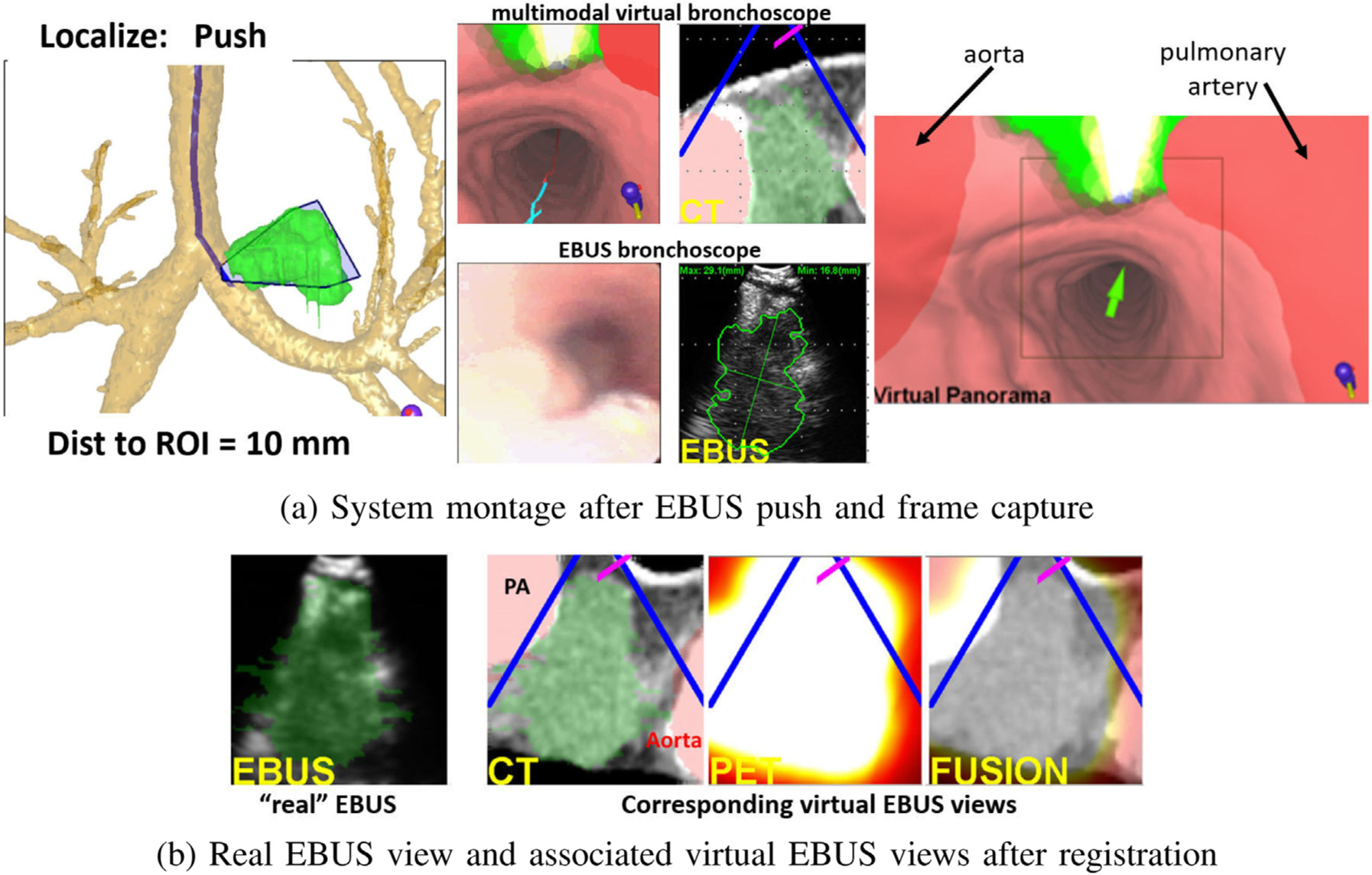
Example system views for a station 4L lymph node with long axis = 5.3 cm and SUVmean = 12.1 (case 20349.3.84). (a) System montage after the final EBUS push operation, showing the results of EBUS segmentation and registration. (b) Real and three associated virtual EBUS views at the final registered site; CT-based ROI (green) is fused onto the real EBUS view.
Fig. 11 illustrates guidance results for a station 11R lymph node. The composite navigation-stage views of Fig. 11a show device progress along the optimal path, while Fig. 11b illustrates a system montage related to localization. Finally, Fig. 11c depicts successful virtual-to-real EBUS registration. Ref. [12] gives an additional system example.
Fig. 11.
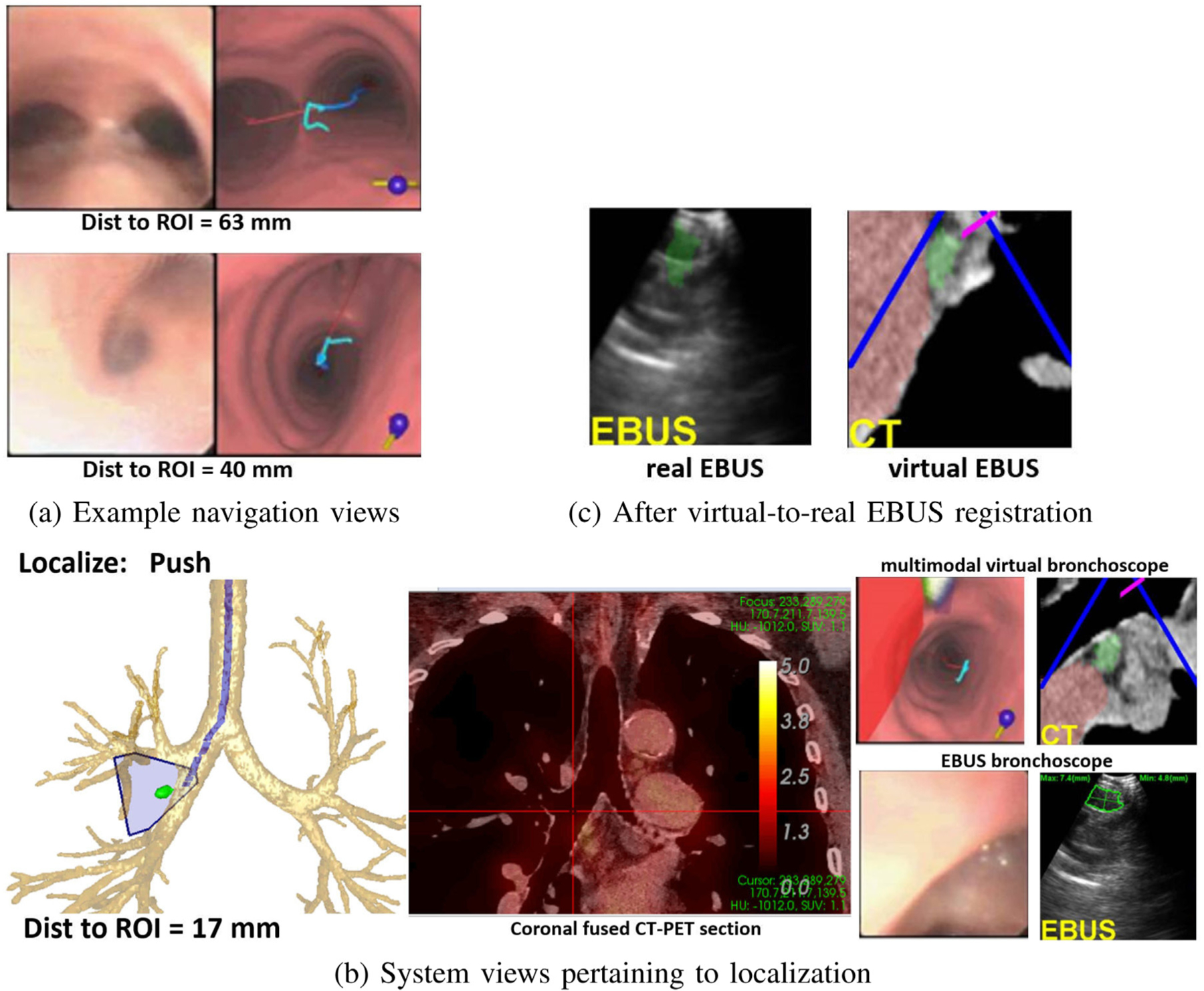
Example system views for a station 11R lymph node (long axis = 1.2 cm, SUVmean = 1.5, case 20349.3.85). (a) Example real and virtual bronchoscope views during navigation; top view — at the main carina, “Navigation: Rotate CW” is the next maneuver; subsequent bottom view in the right main bronchus, ‘Navigation” “Move down” is the next maneuver. (b) System views pertaining to the EBUS push maneuver (red cross hairs on coronal fused 2D CT-PET Slicer denotes device location); Multimodal Virtual Bronchoscope depicts system state just before the push, while the real device views represent the state after pushing the EBUS probe against the airway wall (segmented node in green). (c) Result after virtual-to-real EBUS registration; segmented CT-based node (green) is fused onto the real EBUS view.
3.3. Discussion of prospective study results
Table 1 summarizes the results of the prospective study.
Table 1.
Prospective Study Results (n=13 patients).
| Outcome | Numerical value |
|---|---|
| Lymph nodes correctly localized | 60/60 (100%) |
| Lymph nodes examined per patient | 4.61 ± 1.1 [3, 7] |
| Stations examined per patient | 2.9 ± 0.5 [2, 4] |
| Lymph nodes biopsied | 33/60 |
| Adequate biopsy tissue samples | 30/33 (91%) |
| Procedure time per node | 87.4 s ± 56.6 s [38 s, 301 s] |
The mean procedure time per node includes all real-time interactions, including navigation, localization, EBUS analysis, and biopsies. Table 2 further breaks down procedure time. Nearly 90% of the procedure time occurred during the EBUS-related operations, with nearly half of this time taken by the biopsy-site confirmation steps of the “segment” operation. All EBUS images were successfully segmented and registered. 20 were segmented fully automatically, while 32 required an additional semi-automatic segmentation [46].
The physician correctly localized 60/60 (100%) lymph nodes, with no adverse events occurring during any procedure. On average, 4.61 nodes residing in 2.9 nodal stations were examined per patient. These results compare favorably to a large multi-center EBUS bronchoscopy nodal staging study by Ost et al. where the typical physician only examined nodes in 2.04 stations on average (66% of patients had ≤ 2 stations examined) [9]. Our mean procedure time = 6 min 43 s per patient (4.61 nodes biopsied per patient requiring 87.4 s per node).
We obtained adequate tissue samples for 30/33 (91%) biopsied nodes. The 3 biopsied nodes not yielding adequate samples were in the difficult aortopulmonary window of station 4. This location requires the physician to “thread the needle” so to speak between the large aorta and pulmonary artery complex to reach the desired node, a risky task even with our system’s guidance. We emphasize that the physician correctly localized these sites via our system. For 4 patients, 6 nodes proved to be malignant.
While not a primary outcome for our study, we also considered the impact of having a PET scan. For the 10 patients with a PET scan, 44 nodes were selected. Of these 44 nodes, 14 were confirmed by PET (12 by both CT+PET and 2 by PET only); 25 were later biopsied. For the 3 CT-only patients, 16 nodes were selected with 8 later biopsied. Overall, for the 60 selected nodes over all 13 patients, 11/14 PET-avid nodes were biopsied (10/11 yielded adequate biopsies), while only 22/46 CT-only nodes were biopsied (20/22 adequate biopsies). Hence, PET appeared to influence the choice of nodes to biopsy, but we caution that our sample size is very small.
Table 3 compares our system’s EBUS TBNA performance to results reported for current standard practice [8,48] and for the recently proposed state-of-the-art image-guided EBUS bronchoscopy systems [24–26].
Table 3.
EBUS TBNA performance comparison.
| Approach | Nodes | Biopsy Adequacy | Procedure Time |
|---|---|---|---|
| Proposed System | 2.54 | 91% | 6 min 43 s |
| Current Practice [8, 48] | 1.33 — 3.20 | 77% | 27 min 12 s — 50 min 54 s |
| Sorger [26] | 1.5 | 68% | 24 min 38 s |
| Sato [24] | 1.69 | 82% | not reported |
All measures are per patient. “Nodes” = number of lymph nodes biopsied per patient, “Biopsy Adequacy” = percentage of adequate biopsy samples collected, “Procedure Time” = total live procedure time.).
The current practice results combine the multi-study meta-analysis of Aswanetmanee et al. and the biopsy adequacy results of Hong et al. [8,48]. The meta-study gave results as ranges and reported a diagnostic yield range of 52% — 100% (deep sedation assumed). This aligns with the results of multi-center study by Ost et al. [9]. Also, the diagnostic yield range implies a biopsy adequacy well below 90% (or in line with Hong et al.). Sorger et al. drew upon data for 4 patients, with 6 total nodes biopsied. 13/19 biopsies for the 6 nodes gave adequate samples [26]. They also point out that they did not visualize one of the candidate nodes. Sato et al. biopsied 22 lesions over 13 patients, with 18/22 lesions giving adequate samples [24]. They did not report a procedure time.
Overall, our system improved upon the EBUS TBNA biopsy performance of standard practice and for the recently proposed image-guided systems. In addition, our system appeared to be substantially faster than current practice and the state-of-the-art approaches. This is despite the somewhat greater workload per patient our study incurred. Finally, we point out that our system only requires a standard inexpensive PC workstation, while the other proposed image-guided systems either require expensive electromagnetic navigation hardware [26] or expert assistance in planning a procedure [24]. We strongly caution that our results could be biased by our study’s limited patient population.
4. Conclusion
With over one million patients diagnosed with lung cancer each year worldwide, accurate cancer staging is vital for predicting disease prognosis and prescribing timely treatment. To this point, effective EBUS bronchoscopy and TBNA are crucial. Unfortunately, when using EBUS, the average physician scans the airway walls essentially blindly to localize desired lymph nodes. In addition, even if they localize a node, they do not know if the obtained device position will lead to an adequate safe tissue biopsy.
We have proposed an integrated image-guided system for both planning and guiding EBUS bronchoscopy. To do this, it greatly expands existing single-mode navigation-only image-guided systems to multimodal EBUS bronchoscopy. The system’s real-time guidance strategy provides intuitive seamless image guidance during both device navigation via videobronchoscopy and node localization via EBUS. Procedure planning derives airway guidance routes leading to optimal safe tissue-biopsy sites. During the procedure, the system suggests a preplanned series of device maneuvers to perform, and it provides multimodal visual cues for locating suitable EBUS TBNA sites. Thus, efficient, accurate EBUS bronchoscopy can be performed with less dependence on physician skill.
The system features multimodal visualization tools created to assist with these operations. For the first time, to the best of our knowledge, these tools enable multimodal viewing and fusion of CT-PET imaging data with live videobronchoscopy and EBUS. The Multimodal Virtual Bronchoscope, which serves as the main driving guidance tool, gives the fundamental linkage between the image-based procedure plan (virtual planning space) and live multimodal video/EBUS device views (real patient/surgical space). A Virtual Panorama and EBUS Camera Viewer enable decisive visual confirmation of final nodal biopsy sites.
For the combined retrospective and prospective patient studies, 74/74 selected ROIs (100%) were successfully localized using our system. For the prospective study, run within the framework of the normal clinical workflow, 30/33 nodes biopsied (91%) led to adequate tissue samples, with a mean procedure time of 6 min 43 s Furthermore, our system resides on an inexpensive Windows-based PC. One could reasonably expect the introduction of new technology to breed unfamiliarity and the potential for indecision. Yet, by all measures, our system appears to offer good performance over standard unguided EBUS TBNA and related image-guided EBUS bronchoscopy systems [8,9,25,26,48].
We point out, however, that results of our small pilot study depend on our selected patient cohort. We also note that, as EBUS views are typically noisy, EBUS segmentation accuracy requires some judgment. Given our patient eligibility criteria, we did endeavor to enroll patients in an unbiased manner in our studies. Unidentified sources of residual confounding, however, likely influence our results. Hence, a larger study is needed to sharpen conclusions on overall system efficacy and biopsy success rate [12]. Also, to quote Silvestri et al. [2]: “It is likely that better staging serves as a marker for better care in general. Nevertheless, there can be little doubt that basing treatment decisions on poorly executed staging evaluations may well lead to suboptimal treatment and worse outcomes”.
On a separate note, a recently proposed thinner EBUS bronchoscope with the same integrated configuration as the standard devices used in our work can go deeper into the airway tree [49]. Our system could readily be adapted to this device by tailoring our tools to the smaller device’s tip specifications. Finally, our methodology could prove useful for comprehensive central-chest nodal staging (“all” viable stations considered), conceivably done by a robotic device [5].
Supplementary Material
Acknowledgments
This work was partially supported by grant R01-CA151433 from the National Cancer Institute, United States of the NIH.
Footnotes
Declaration of competing interest
William E. Higgins and Penn State have an identified conflict of interest and financial interest related to this research. These interests have been reviewed by the University’s Institutional and Individual Conflict of Interest Committees and are currently being managed by the University and reported to the NIH.
Appendix A. Supplementary data
Supplementary material related to this article can be found online at https://doi.org/10.1016/j.imu.2021.100665. Supplement includes a short video of the complete guidance system interface showing the final push maneuver.
References
- [1].Tanoue LT. Lung cancer staging. Clin Chest Med 2020;41(2):161–74. [DOI] [PubMed] [Google Scholar]
- [2].Silvestri G, Gonzalez A, Jantz M, Margolis M, et al. Methods for staging non-small cell lung cancer: Diagnosis and management of lung cancer, 3rd ed: American College of Chest Physicians evidence-based clinical practice guidelines. Chest 2013;143(5):e211S–50S. [DOI] [PubMed] [Google Scholar]
- [3].Bray F, Ferlay J, Soerjomataram I, Siegel R, Torre L, Jemal A. Global cancer statistics 2018: GLOBOCAN estimates of incidence and mortality worldwide for 36 cancers in 185 countries. CA Cancer J Clin 2018;68(6):394–424. [DOI] [PubMed] [Google Scholar]
- [4].Rami-Porta R, Call S, Dooms C, Obiols C, Sánchez M, Travis WD, et al. Lung cancer staging: a concise update. Eur Respir J 2018;51(5):1–17. [DOI] [PubMed] [Google Scholar]
- [5].Wahidi M, Herth F, Chen A, Cheng G, Yarmus L. State of the art: Interventional pulmonology. Chest 2020;157(3):724–36. [DOI] [PubMed] [Google Scholar]
- [6].Sheski F, Mathur P. Endobronchial ultrasound. Chest 2008;133(1):264–70. [DOI] [PubMed] [Google Scholar]
- [7].Kinsey CM, Arenberg DA. Endobronchial ultrasound–guided transbronchial needle aspiration for non–small cell lung cancer staging. Am J Resp Crit Care Med 2014;189(6):640–9. [DOI] [PubMed] [Google Scholar]
- [8].Aswanetmanee P, Limsuwat C, Kabach M, Hamid Alraiyes A, Kheir F. The role of sedation in endobronchial ultrasound-guided transbronchial needle aspiration: Systematic review. Endo Ultrasound 2016;5(5):300–6. [DOI] [PMC free article] [PubMed] [Google Scholar]
- [9].Ost DE, Ernst A, Lei X, Feller-Kopman D, et al. Diagnostic yield of endobronchial ultrasound-guided transbronchial needle aspiration: results of the AQuIRE Bronchoscopy Registry. Chest 2011;140(6):1557–66. [DOI] [PMC free article] [PubMed] [Google Scholar]
- [10].Folch E, Majid A. Point: are > 50 supervised procedures required to develop competency in performing endobronchial ultrasound-guided transbronchial needle aspiration for mediastinal staging? Yes. Chest 2013;143(4):888–91. [DOI] [PubMed] [Google Scholar]
- [11].Wahidi M, Hulett C, Pastis N, Silvestri G, et al. Learning experience of linear endobronchial ultrasound among pulmonary trainees. Chest 2014;145(3):574–8. [DOI] [PubMed] [Google Scholar]
- [12].Zang X, Gibbs J, Cheirsilp R, Byrnes P, Toth J, Bascom R, et al. Optimal route planning for image-guided EBUS bronchoscopy. Comput Biol Med 2019;112(7):103361. [DOI] [PMC free article] [PubMed] [Google Scholar]
- [13].Asano F. Practical application of virtual bronchoscopic navigation. In: Mehta A, Jain P, editors. Interventional bronchoscopy. Respir. med, vol. 10, Humana Press; 2013, p. 121–40. [Google Scholar]
- [14].Reynisson P, Leira H, Hernes T, Hofstad E, et al. Navigated bronchoscopy: a technical review. J Bronchol Interv Pulmonol 2014;21(3):242–64. [DOI] [PubMed] [Google Scholar]
- [15].Herth FJ, Eberhardt R, Schuhmann M. Bronchoscopy in lung cancer: navigational modalities and their clinical use. Exp Rev Respir Med 2016;10(8):901–6. [DOI] [PubMed] [Google Scholar]
- [16].Merritt SA, Gibbs JD, Yu KC, Patel V, Rai L, Cornish DC, et al. Real-time image-guided bronchoscopy for peripheral lung lesions: A phantom study. Chest 2008;134(5):1017–26. [DOI] [PubMed] [Google Scholar]
- [17].Vining DJ, Liu K, Choplin RH, Haponik EF. Virtual bronchoscopy: Relationships of virtual reality endobronchial simulations to actual bronchoscopic findings. Chest 1996;109(2):549–53. [DOI] [PubMed] [Google Scholar]
- [18].Bricault I, Ferretti G, Cinquin P. Registration of real and CT-derived virtual bronchoscopic images to assist transbronchial biopsy. IEEE Trans Med Imaging 1998;17(5):703–14. [DOI] [PubMed] [Google Scholar]
- [19].Higgins WE, Ramaswamy K, Swift R, McLennan G, Hoffman EA. Virtual bronchoscopy for 3D pulmonary image assessment: State of the art and future needs. Radiographics 1998;18(3):761–78. [DOI] [PubMed] [Google Scholar]
- [20].Gibbs J, Graham MW, Bascom R, Cornish D, Khare R, et al. Optimal procedure planning and guidance system for peripheral bronchoscopy. IEEE Trans Biomed Eng 2014;61(3):638–57. [DOI] [PMC free article] [PubMed] [Google Scholar]
- [21].Mori K, Hasegawa J, Toriwaki J, Anno H, Katada K. A fast rendering method using the tree structure of objects in virtualized bronchus endoscope system. In: Hohne KH, Kikinis R, editors. Visualization in biomedical computing. LNCS, vol. 1131, 1996, p. 33–42. [Google Scholar]
- [22].Summers RM. Navigational aids for real-time virtual bronchoscopy. Am J Roentgenol 1997;168(5):1165–70. [DOI] [PubMed] [Google Scholar]
- [23].Merritt S, Khare R, Bascom R, Higgins W. Interactive CT-video registration for image-guided bronchoscopy. IEEE Trans Med Imaging 2013;32(8):1376–96. [DOI] [PMC free article] [PubMed] [Google Scholar]
- [24].Sato M, Chen F, Aoyama A, Yamada T, Ikeda M, Bando T, et al. Virtual endobronchial ultrasound for transbronchial needle aspiration. J Thoracic Cardiovas Surg 2013;146(5):1204–12. [DOI] [PubMed] [Google Scholar]
- [25].Sorger H, Hofstad EF, Leira HO, et al. A novel platform for electromagnetic navigated ultrasound bronchoscopy (EBUS). Int J Comp Assist Radiol Surg 2016;13, pp. on–line. [DOI] [PMC free article] [PubMed] [Google Scholar]
- [26].Sorger H, Hofstad E, Amundsen T, Lango T, Bakeng J, Leira H. A multimodal image guiding system for Navigated Ultrasound Bronchoscopy (EBUS): A human feasibility study. PLoS One 2017. [DOI] [PMC free article] [PubMed] [Google Scholar]
- [27].Tamiya M, Okamoto N, Sasada S, Shiroyama T, Morishita N, Suzuki H, Yoshida E, Hirashima T, Kawahara K, Kawase I. Diagnostic yield of combined bronchoscopy and endobronchial ultrasonography, under LungPoint guidance for small peripheral pulmonary lesions. Respirology 2013;18(5):834–9. [DOI] [PubMed] [Google Scholar]
- [28].Luo X, Mori K. Beyond current guided bronchoscopy: A robust and real-time bronchoscopic ultrasound navigation system. In: Mori K, Sakuma I, Sato Y, Barillot C, Navab N, editors. MICCAI 2013.Lecture notes in computer science, vol. 8149, Springer; 2013, p. 388–95. [DOI] [PubMed] [Google Scholar]
- [29].Boellaard R, Delgado-Bolton R, Oyen WJ, Giammarile F, Tatsch K, Eschner W, et al. FDG PET/CT: EANM procedure guidelines for tumour imaging: version 2.0. Eur J Nucl Med Mol Imaging 2015;42(2):328–54. [DOI] [PMC free article] [PubMed] [Google Scholar]
- [30].Gibbs JD, Graham MW, Higgins WE. 3D MDCT-Based system for planning peripheral bronchoscopic procedures. Comput Biol Med 2009;39(3):266–79. [DOI] [PMC free article] [PubMed] [Google Scholar]
- [31].Graham MW, Gibbs JD, Cornish DC, Higgins WE. Robust 3D airway-tree segmentation for image-guided peripheral bronchoscopy. IEEE Trans Med Imaging 2010;29(4):982–97. [DOI] [PubMed] [Google Scholar]
- [32].Yu KC, Ritman EL, Higgins WE. System for the analysis and visualization of large 3D anatomical trees. Comput Biol Med 2007;37(12):1802–20. [DOI] [PMC free article] [PubMed] [Google Scholar]
- [33].Taeprasartsit P, Higgins WE. Robust extraction of the aorta and pulmonary artery from 3D MDCT images. In: Dawant B, Haynor D, editors. SPIE medical imaging 2010: Image processing, vol. 7623. 2010, p. 76230H–1–76230H–17. [Google Scholar]
- [34].Taeprasartsit P, Higgins WE. Robust method for extracting the pulmonary vascular trees from 3D MDCT images. In: Dawant B, Haynor D, editors. SPIE medical imaging 2011: Image processing, vol. 7962. 2011, p. 796237–1–796237–17. [Google Scholar]
- [35].Cheirsilp R, Bascom, Allen T, Higgins W. Thoracic cavity definition for 3D PET/CT analysis and visualization. Comput Biol Med 2015;62:222–38. [DOI] [PMC free article] [PubMed] [Google Scholar]
- [36].Lu K, Higgins WE. Interactive segmentation based on the live wire for 3D CT chest image analysis. Int J Comput Assist Radiol Surg 2007;2(3–4):151–67. [Google Scholar]
- [37].Lu K, Higgins WE. Segmentation of the central-chest lymph nodes in 3D MDCT images. Comput Biol Med 2011;41(9):780–9. [DOI] [PMC free article] [PubMed] [Google Scholar]
- [38].Cheirsilp R, Bascom R, Allen T, Mahraj R, Higgins WE. Deformable image registration for multimodal lung-cancer staging. In: Styner M, Angelini E, editors. SPIE medical imaging 2016: Image processing, vol. 9784. 2016, p. 9784Z–1–9784Z–10. [Google Scholar]
- [39].Vasiliev V, Bascom R, Toth J, Higgins WE. Autonomous planning and guidance for convex-probe endobronchial ultrasound bronchoscopy. In: Linte C, Siewerdsen J, editors. SPIE medical imaging 2021: Image-guided procedures, robotic interventions, and modeling, vol. 11598. 2021, p. 115980T–1–115980T–10. [Google Scholar]
- [40].Nadeem SM. Fiberoptic bronchoscopy: the technique. 2009, educational material from Committee for European Education in Anesthesiology. [Google Scholar]
- [41].Khare R, Bascom R, Higgins W. Hands-free system for bronchoscopy planning and guidance. IEEE Trans Biomed Eng 2015;62(12):2794–811. [DOI] [PMC free article] [PubMed] [Google Scholar]
- [42].Yu KC, Gibbs JD, Graham MW, Higgins WE. Image-based reporting for bronchoscopy. J Digit Imaging 2010;23(1):39–50. [DOI] [PMC free article] [PubMed] [Google Scholar]
- [43].Flood B, Rai L, Higgins WE. System for robust bronchoscopic video distortion correction. In: Wong KH, Holmes DR, editors. SPIE medical imaging 2011: Visualization, image-guided procedures, and modeling, vol. 7964. 2011, p. 79641L–1–79641L–16. [Google Scholar]
- [44].Helferty JP, Zhang C, McLennan G, Higgins WE. Videoendoscopic distortion correction and its application to virtual guidance of endoscopy. IEEE Trans Med Imaging 2001;20(7):605–17. [DOI] [PubMed] [Google Scholar]
- [45].Helferty JP, Sherbondy AJ, Kiraly AP, Higgins WE. Computer-based system for the virtual-endoscopic guidance of bronchoscopy. Comput Vis Image Underst 2007;108(1–2):171–87. [DOI] [PMC free article] [PubMed] [Google Scholar]
- [46].Zang X, Bascom R, Gilbert C, Toth J, Higgins W. Methods for 2-D and 3-D endobronchial ultrasound image segmentation. IEEE Trans Biomed Eng 2016;63(7):1426–39. [DOI] [PMC free article] [PubMed] [Google Scholar]
- [47].Higgins W, Zang X, Cheirsilp R, Byrnes P, Kuhlengel T, Toth J, et al. Optimal multimodal virtual bronchoscopy for convex-probe endobronchial ultrasound. In: Fei B, Webster R, editors. SPIE medical imaging 2018: Image-guided procedures, robotic interventions, and modeling, vol. 10576. 2018, p. 1057618–1–1057618–6. [Google Scholar]
- [48].Hong G, Koo J. Evaluation of the gauge of needles used in the collection of specimens during endobronchial ultrasound-guided transbronchial needle aspiration. J Bras Pneumol 2019;45(1):e20180090. [DOI] [PMC free article] [PubMed] [Google Scholar]
- [49].Fujino K, Ujiie H, Kinoshita T, Yasufuku K, et al. First evaluation of the next-generation endobronchial ultrasound system in preclinical models. Ann Thorac Surg 2019;107(5):1464–71. [DOI] [PubMed] [Google Scholar]
Associated Data
This section collects any data citations, data availability statements, or supplementary materials included in this article.