Abstract
A personal perspective on the practice of drawing polycyclic molecules and its implications for understanding and undertaking chemistry is presented.
Introduction
As a student and practitioner of organic chemistry, I have had occasion to draw many polycyclic molecules. I have thought much (some would say too much) about these experiences and their implications for how I perceive and do chemistry. Some of these episodes and some of what I have learned from them are described below.
PF1018 and Chem 115
When I was a senior in college, I took an advanced organic chemistry class, which focused on the logic and methods of total synthesis. Part of my grade in Chem 115 was based on a written proposal for the synthesis of a previously unsynthesized organic molecule of my choosing. If memory serves me right, this is where my adventures in polycyclic artwork began. As part of this assignment, I had to prepare a transparency showing a picture of my chosen target molecule for presentation to the class. This was, I think, the part of the assignment that had the most lasting consequences for my development as a chemist.
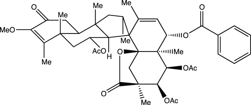
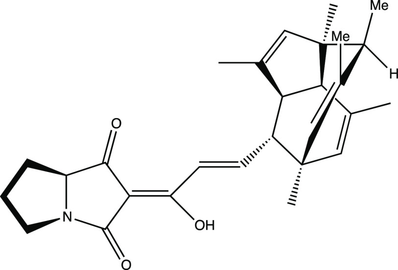
My assault on this assignment began in the chemistry library. After hours and hours of essentially random flipping through journals in search of a suitable target molecule, I had narrowed my candidates to two: spirocaracolitone and PF1018. The structures of these, as drawn in the original papers on their isolation,1 are shown in Figure 1.2
Figure 1.
Drawings of spirocaracolitone and PF1018 based on how they appeared in the literature reports on their isolation.1 Only the structures are shown; atom numbers and additional labels appearing in the original images are not included here.
Having not yet decided which molecule to choose, I set about producing overheads for both molecules. I was taught that it is very important to have a “good” picture of one’s target molecule since this can promote effective retrosynthetic analysis,3,4 but it was clear to me that constructing realistic pictures of polycyclic systems such as these (here, the criteria for realism was successful conveyance, in a semiquantitative sense, of the relative positions of the atomic nuclei in a given molecule) would first require the construction of three-dimensional models of the molecules in question.5 My previous undergraduate organic chemistry classes had advocated, time and again, the use of molecular models for such purposes, so I had already acquired a model set from the chemistry stockroom, one that I would grow to cherish almost as much as the LEGO sets of my childhood. While I did not spend much time modeling and drawing spirocaracolitone (Figure 2 shows the drawing that I produced; I made only minor changes from the drawing in the literature, primarily to make things look less crowded6), I spent quite some time building and playing with a model of PF1018. Eventually, I settled on the drawing shown in Figure 3. Due in large part to the fact that I did not truly appreciate its structure until I had built a model of it, I ultimately decided that PF1018 would be my top choice for the assignment, and spirocaracolitone would serve only as my backup synthetic target.
Figure 2.
Author’s drawing of spirocaracolitone for Chem 115.
Figure 3.
Author’s drawing of PF1018 for Chem 115.
I brought my drawings of PF1018 and spirocaracolitone to class. I was one of the final students to show my target molecule (I always hated oral presentations and, as usual, hid until the last possible moment), and when I finally approached the overhead projector at the front of the classroom, I was not carrying a picture of PF1018 but rather one of spirocaracolitone. It just so happened that several other students had already presented drawings of PF1018! I was left with my backup. Although PF1018 is not a particularly important molecule from an applications standpoint, its aesthetic appeal had apparently made it a popular choice among my classmates. In any case, the professor was actually enthusiastic about my choice of spirocaracolitone—more so than I was—and so I went off and produced a not-so-noteworthy proposal for its synthesis.
What I have neglected so far to mention is that when I returned home after class, I rushed to re-examine my model of PF1018. One of my classmates had presented a drawing of this molecule that I thought was extremely “cool”—much more so than my own—and I had to see how he had come up with it! I did not ask for a copy of his drawing, but instead, armed with the realization that such a drawing was possible, I set about constructing my own. I turned my model round and round until I found an orientation that I thought was similar to that captured in my classmate’s artwork (Figure 4) and put pencil to paper. Finally, I arrived at the picture of the PF1018 polycyclic core (i.e., without the diene and heterocyclic ring system) shown in Figure 5.
Figure 4.
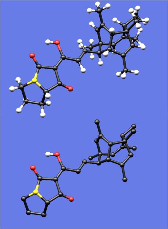
Model of PF1018, with and without alkyl hydrogens included. Although this model was created with a computer, it faithfully reproduces the color scheme and relative sizes of the balls and sticks in the plastic model set used to construct the author’s original PF1018 model.
Figure 5.
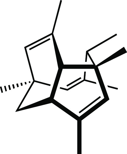
Core of PF1018.
Why did I (and do I) feel that my final drawing—as well as that of my classmate—was far superior to my earlier attempt? First and foremost, the later drawing looks cooler. This is not a trivial point. I know that I am more apt to pursue the study of a particular molecule or any scientific problem if I perceive it as beautiful.4,7 Second, the later drawing better expresses the three-dimensional geometry of the molecule. For example, the conformations of each of the rings in the polycyclic core are conveyed explicitly (to the extent that certain iconic representations are translated in the minds of organic chemists into conceptions of certain geometric structures,4 often via images of their particular favorite plastic or metal models5). In short, my second picture just looked more like my plastic model.
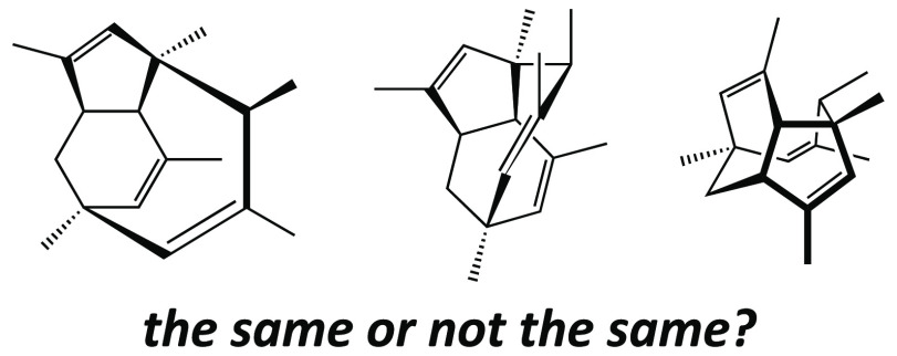
Being able to capture and convey the shape of a three-dimensional structure on a flat piece of paper is an extremely valuable skill to have when planning and presenting a synthesis, since most chemical reactions have rather rigid spatial/geometric/stereochemical requirements for their success. The style one chooses for his or her structural drawings also can affect which retrosynthetic disconnections are made when designing a synthesis, since different representations tend to emphasize and de-emphasize particular elements of a structure.4,8 Much later, upon seeing my different drawings of PF1018, a colleague commented that my original drawing and that found in ref (1b) (Figures 1 and 3) suggested to him a synthetic approach based on a ring-closing metathesis reaction, while my later drawing (Figure 5) suggested a strategy based on a Cope rearrangement—an insight undoubtedly inspired by the fact that the conformation of the nine-membered ring shown in this drawing evoked images of boat-like transition state structures for Cope rearrangements that he had encountered previously.
My PF1018 experience (and another, described below) prompted me to design a handout that I distributed to the students in one of my first discussion sections as a teaching assistant (for a summer school organic chemistry class during the summer after I graduated and before I left for graduate school). As part of this handout, one of a series on the symbols used by organic chemists, I showed three drawings of the polycyclic core of PF1018 that corresponded to the representation found in the original literature,1b the drawing that I almost presented, and my revised drawing, respectively (Figure 6). When compared, it is clear that these drawings vary in the quantity and quality of information that they convey—increasing, in my opinion, from left to right. To my eye, the visual appeal of these structures increases in the same order. My intention in creating this handout was to share with my students something with which just about every organic chemist has had to come to terms at some point, something that I had only recently begun to digest: it can be quite difficult both to draw three-dimensional structures in two dimensions and also to translate two-dimensional drawings of chemical structures into useful images of three-dimensional molecules. In fact, even recognizing that the second and third structures in Figure 6 represent the same molecule is far from an easy endeavor. The discourse that accompanied this handout was probably my first plea to students to build and play with molecular models.
Figure 6.
Alternative drawings of the core of PF1018 used in a handout developed by the author.
Platonic Relationships
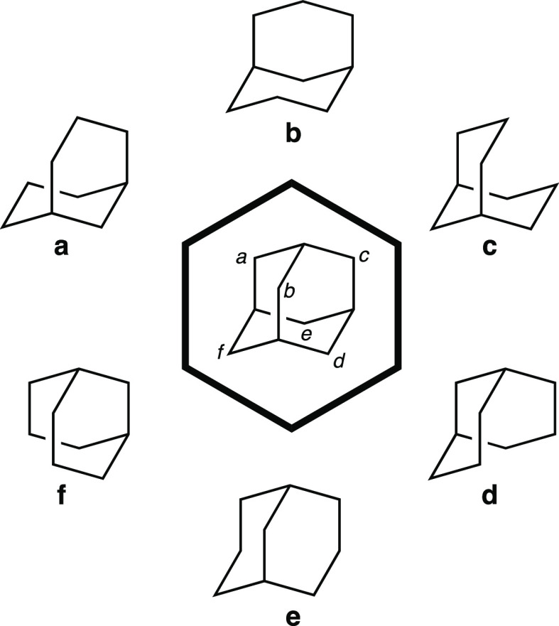
In the center of Figure 7 is shown adamantane, a classic tricyclic hydrocarbon (with tetrahedral, Td, symmetry) to which most organic chemistry students are exposed at some point. Removing any nonbridgehead carbon of adamantane will lead to the same bicyclic hydrocarbon since all of adamantane’s CH2 groups are indistinguishable by symmetry (specifically, they are homotopic). However, removing each of Ca–Cf (labeled based on the orientation of adamantane shown in Figure 7) leads to six different pictures of the same bicyclic molecule, most of which look quite different from each other.
Figure 7.
Fragments (a–f) of adamantane (center).
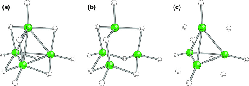
Another example is shown in Figure 8, here using ball-and-stick-style structures (B atoms are green, and H atoms are white). The structure shown is the B4H102+ dication, its geometry optimized using quantum chemistry. In the representation in (a), gray lines indicate the closest B–B and B–H contacts. To my eye, this image is a bit crowded. In the representation in (b), only B–H contacts are shown, emphasizing the relationship of the structure to that of adamantane. In the representation in (c), only B–B and nonbridging B–H contacts are shown, emphasizing the tetrahedral symmetry of B4H102+. In all three representations, the positions of all atoms are identical, but each image conveys different information by highlighting different aspects of the overall structure.
Figure 8.
Three representations of the B4H102+ dication. B atoms are green, and H atoms are white. (a) Gray lines indicating the closest B–B and B–H contacts. (b) Only B–H contacts shown, emphasizing the relationship of the structure to that of adamantane. (c) Only B–B and nonbridging B–H contacts shown, emphasizing the relationship of the structure to that of tetrahedrane (in this case, with all six edges of the tetrahedron capped with H atoms). The relative positions of all the atoms are identical in each case. None of these representations is meant here to indicate B–B and B–H bond orders, a topic of substantial debate in the history of borane chemistry.
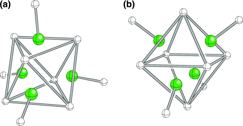
The bridging hydrogens in B4H102+ also define an octahedron, although that is far from obvious in the representations shown in Figure 8. However, consider the representations in Figure 9, where the hydrogen atoms that define the corners of the octahedron are connected. The remaining four B–H groups cap four faces of the octahedron. The orientation in (a) corresponds to that of the structures in Figure 8, while the structure has been reoriented in (b) so as to show the octahedron in a more familiar orientation.
Figure 9.
Two additional representations of the B4H102+ dication. In both, the octahedral relationship of the bridging H atoms is emphasized. The remaining four B–H groups cap four faces of the octahedron. The orientation of the dication in (a) is similar to that of the structures in Figure 8, while the dication has been reoriented in (b) so as to show the octahedron in a more familiar orientation.
Discovering Tricyclene, Twice
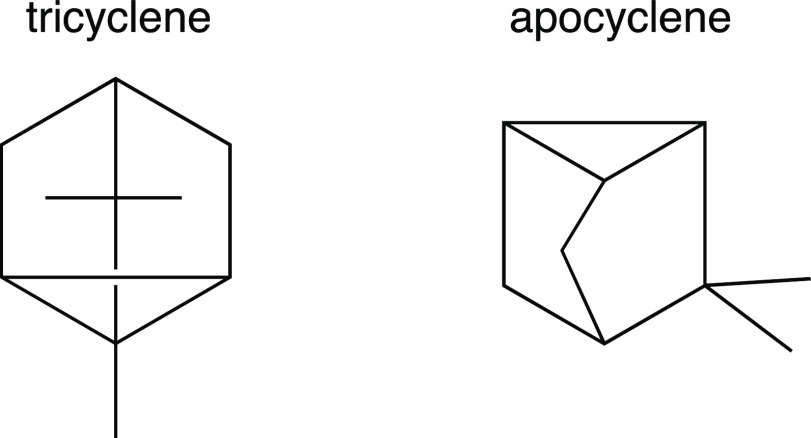
It was during that same summer before graduate school that I had a similarly enlightening encounter with another polycyclic structure. On occasion, I found myself flipping through the Merck Index9—a hefty volume containing brief descriptions and physical properties of many organic compounds of biological interest. In doing so, I came across two molecules—tricyclene and apocyclene—that I thought looked interesting. Both were polycyclic hydrocarbons, and their structures, as drawn in the Merck Index, are shown in Figure 10.
Figure 10.
Drawings of tricyclene and apocyclene first encountered by the author.
I found these molecules intriguing enough that I built a model of each. After examining the two models from various perspectives, I came to the striking realization that tricyclene and apocyclene differed in structure by only the presence or absence of a single methyl group! Their polycyclic cores were identical, yet I had not noticed! Perhaps this points to my lack of practice at the time in translating two-dimensional drawings into three-dimensional structures. However, even today, after years of practice, I still have some difficulty seeing the relationship between the structures depicted in Figure 10 without intensive concentration or the aid of molecular models. Although the choice of format used for each drawing may have had as much to do with typesetting conventions and history as with information content and visual appeal, it is still noteworthy that very different representations were chosen for the two.
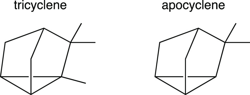
I was discouraged at first by my failure to make the connection between tricyclene and apocyclene, but soon my insecurity gave way to excitement; making a connection on my own, no matter how late in coming, was still satisfying. Then, of course, I began to think about why making that connection was so difficult. That, no doubt, had much to do with the fact that the pictures of tricyclene and apocyclene in Figure 10 do little to communicate three-dimensionality and perspective—that of apocyclene in particular does not look like my model from any viewing angle. I set out to come up with my own two-dimensional drawing of this polycyclic ring system and, after several balks, arrived at the drawings shown in Figure 11. I found, and find, these pictures to be more appealing than those in Figure 10 because, again, they actually look like my models—but does that really matter?
Figure 11.
Redrawn images of tricyclene and apocyclene.
Traditional and Nontraditional Representations of Nonclassical Ions
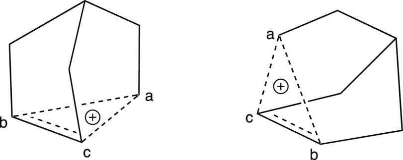
In graduate school, I became enamored with a historical controversy called the “nonclassical ion problem”.10 At the center of this controversy was a ferocious debate over the structure of the norbornyl cation. After years of intensive experimental and theoretical research, it is now generally accepted that this species possesses two electrons that are delocalized over three carbon atoms in a symmetrical fashion.11 The most common representations of this structure are shown in Figure 12.10f−10h Each of these pictures conveys important information in a format interpretable by organic chemists. Most importantly, all capture the fact that the distance between carbon a and carbon b or carbon c is longer than that for a typical single bond; following standard conventions, this is of course indicated by the dashed (or broken or partial) lines connecting carbon a to carbons b and c.
Figure 12.
Common styles of drawing the nonclassical norbornyl cation. Atoms are labeled (a–c) to facilitate comparison between structures.
These representations differ, however, in the type and quantity of additional information that they readily relate. The first two pictures emphasize the relationship between the norbornyl cation and the norbornane ring system found in many of its precursors, which is commonly drawn as shown in Figure 13 (for a brosylated precursor). The Cs symmetry of the norbornyl cation structure, however, and therefore the equivalence of carbons b and c, is more apparent in the third drawing of Figure 12 (to a first approximation, this representation is related to the first two by a 90° rotation through an axis perpendicular to the plane of the paper). In addition, the second representation communicates the fact that the distance between carbons b and c is intermediate between that of a typical single and typical double bond, something that is not apparent from the other two pictures.
Figure 13.
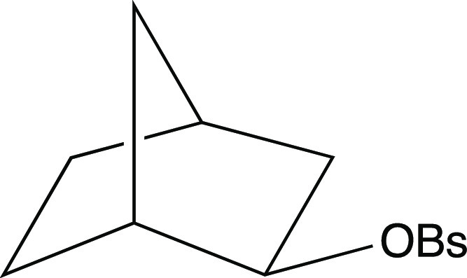
Precursor to the nonclassical norbornyl cation. OBs = brosylate.
From a purely personal aesthetic perspective, I prefer an alternative representation—that shown at the left of Figure 14—because, to my eye, it best conveys the three-dimensional geometry that I imagine this molecule has. Incidentally, the relationship of this structure to those of tricyclene and apocyclene becomes clear when it is represented in this way (compare Figures 11 and 14). I also like the representation at the right of Figure 14 for similar reasons. It turns out that both of these representations capture many of the geometric features that come out of high-level quantum mechanical calculations and, more recently, X-ray crystallographic structures.12 Even though the results of such computations did not arrive on the scene till the latter days of the structural debate, and the crystallographic results came much later, representations similar to those in Figure 14 did appear in the earlier nonclassical cation literature.10f−10h Still, these were much less common than the representations shown in Figure 12, and it is not obvious why this is so. Personally, I did not encounter either of the representations in Figure 14 in my own undergraduate and graduate organic chemistry classes—although I now relish showing them when I teach physical organic chemistry.
Figure 14.
Redrawn images of the norbornyl cation. Atoms are labeled (a–c) to facilitate comparison between structures.
One key structural feature, however, is not effectively conveyed by any of the representations in Figures 12 and 14. The fact that carbon a is connected—through single or at least partial single bonds—to five nearest neighbors is all but lost to the casual observer. I know from personal experience as both a student and a teacher that the number of invisible (or implied) hydrogen atoms connected to carbon a (there are two) is not obvious. Why organic chemists like myself resist showing these hydrogens explicitly is not clear—perhaps it has to do with a desire to avoid mixing our metaphors,4 to avoid implying the presence of some hydrogen atoms and not others.13 Nonetheless, which wins out—information content, convention, or visual appeal—depends on the particular illustrator and the context in which the illustration is to be used; a specific example of this is described below.
Choosing the “Worst” Picture for Publication
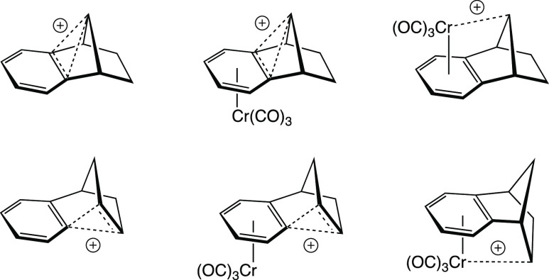
As a graduate student, I had an interest in the effects organometallic fragments (such as chromium tricarbonyl, Cr(CO)3) might have on the structure and stability of nonclassical cations when the two were bound together. Bruce Hietbrink, a friend and colleague, was also interested in this subject, and together we performed extensive quantum mechanical calculations to try and address this issue.14 In particular, we were interested in the benzo-fused cations shown in Figure 15.
Figure 15.
Structures of cations redrawn as in ref (14).
The question of interest here is why we chose to represent these structures as shown in Figure 15. This may seem like a minor problem to some, but it was a source of much contention for us. We needed to resolve two main issues: first, from what perspective to draw the structures, and second, in what style.
The first of these issues is primarily scientific. The problem was essentially to decide how best to convey the structural information obtained from our calculations to an audience of non-computational chemists (who, we knew, would prefer line drawings to ball-and-stick images). Being a proponent of representations such as that shown in Figure 14, I initially suggested that we use pictures such as the one shown in Figure 16 for the species in the bottom row of Figure 15. I still prefer this type of representation to those used in our paper, but I also believe that we chose the best representation given the nature of our report. Ultimately, we decided that it was important to show all of the structures from the same viewing angle so as to promote direct comparison, and we settled on the perspective shown in Figure 15 because it resulted in reasonable representations for all of the structures. We felt that reorienting some of the molecules (as in Figure 16) would confuse the science despite pleasing the eye (at least my eye).
Figure 16.
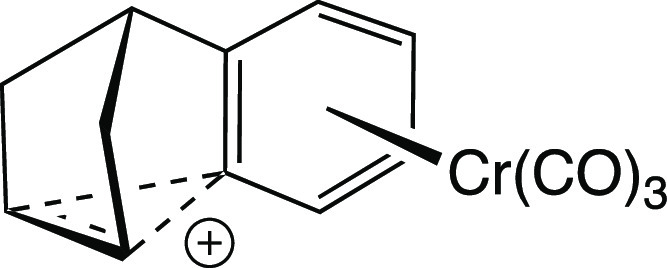
Author’s preferred drawing of one cation from Figure 15 (bottom, center).
The second issue is merely one of visual appeal—the seemingly minor issue of which lines in Figure 15, each representing a bond, should be bolder than others. But it was this issue that actually took the most effort to settle. In fact, Bruce and I spent a long lunch one afternoon arguing about one particular line! We were trying to decide between the two structures shown in Figure 17. The difference between these is subtle—many would deem it insignificant—but to us, on that particular day, it was very important (for the record, most of our arguments about chemistry involved deeper issues, but none that I can remember was as animated as this one). At the heart of the issue was the fact that there are really two styles (at least) of using bold lines in the organic literature.15 One uses solid bold lines for the bonds closest to the viewer, and the other augments these with lines that taper from bold close to the viewer to thin farther away in an effort to provide an additional sense of perspective and three-dimensionality. After a rather heated discussion about which type of representation would better convey the chemical information that we wanted to convey, we reached an impasse and decided to agree that both had merits in this regard. Ultimately, the issue was settled by a game of air hockey. This fact may be troubling to some, but it is nevertheless true.16 I would say that it was a relatively peaceful solution given that we were really arguing about personal aesthetic preferences.
Figure 17.
Drawings of the bottom left cation from Figure 15 differing only in the depiction of the rightmost C–C bond.
So What?
Perhaps no one else cares which picture of PF1018, tricyclene, or the norbornyl cation that I find most appealing or that I prefer to use tapered lines to show perspective in my structural drawings. However, that is exactly the point. Science is a very personal endeavor, and perceptions of beauty most definitely influence which projects we choose to pursue, how we choose to pursue them, and how we choose to present the results of our research. There is power in lines that chemists draw to represent bonds—power to influence, for good or bad.17 Also, perhaps some may disparage my fondness for playing with molecular models, but I think this activity also has great value.5,18 Inspiration and enlightenment do not always arise out of stubborn seriousness—sometimes they arise out of play—and I can see no reason to fight against that.
Acknowledgments
I thank the following people for their encouragement in general and for their excellent comments and suggestions regarding this essay in particular: Sami Bahmanyar, Bruce Hietbrink, Corrie Kuniyoshi, Jennifer Tantillo, Jennifer Cho, Eric Francoeur, Croix Laconsay, and Roald Hoffmann.
The author declares no competing financial interest.
References
- a MacKinnon S. L.; Durst T.; Arnason J. T.; Bensimon C.; Sanchez-Vindas P. E.; San Roman L.; Poveda L. J.; Hasbun C. Spirocaracolitone Isolated from a New Genus and Species, Ruptiliocarpon caracolito. The First CD Spiro-triterpenoid. Tetrahedron Lett. 1994, 35, 1385–1388. 10.1016/S0040-4039(00)76225-3. [DOI] [Google Scholar]; b Gomi S.; Imamura K.-I.; Yaguchi T.; Kodama Y.; Minowa N.; Koyama M. PF1018, A Novel Insecticidal Compound Produced by Humicola sp. J. Antibiot. 1994, 47, 571–580. 10.7164/antibiotics.47.571. [DOI] [PubMed] [Google Scholar]
- a Both are polycyclic systems, evidence that my current distaste for the synthesis of ″molecular lines″ was already growing; b Also of note is the obvious difference in the sound of their names—one a rather melodious mixture of chemical and biological identifiers, and the other a painful-to-pronounce alphanumeric codename. While not often discussed, I believe that this type of consideration—in addition to the issues of visual pleasure discussed throughout this essay—does play some role in our choosing of scientific pursuits as well as radio stations and baby names.; c PF1018 would return to my life many years later, in 2008. I discussed it with Dirk Trauner and ran some preliminary calculations related to an early iteration of his total synthesis of PF1018. The final iterationQuintela-Varela H.; Jamieson C. S.; Shao Q.; Houk K. N.; Trauner D. Bioinspired Synthesis of (−)-PF-1018. Angew. Chem. 2020, 132, 5301–5305. 10.1002/ange.201912452. [DOI] [PMC free article] [PubMed] [Google Scholar]
- See; Corey E. J.; Cheng X.-M.. The Logic of Chemical Synthesis; Wiley: New York, 1989. [Google Scholar]
- The process of producing a two-dimensional representation of a three-dimensional molecule is far from trivial, however. It involves many conventions that comprise the graphical ″language″ used to present information on the structure and reactivity of organic molecules—these connections between chemical representations and language have already been discussed elsewhere. See, for example; a Hoffmann R.; Laszlo P. Representation in Chemistry. Angew. Chem., Int. Ed. Engl. 1991, 30, 1–16. 10.1002/anie.199100013. [DOI] [Google Scholar]; b Hoffmann R.The Same and Not the Same; Columbia University Press: New York, 1997; Chapter 16. [Google Scholar]
- a Laszlo P. Playing with Molecular Models. HYLE 2000, 6, 85–97. [Google Scholar]; b Francoeur E. Beyond Dematerialization and Inscription: Does the Materiality of Molecular Models Really Matter?. HYLE 2000, 6, 63–84. [Google Scholar]; c Francoeur E. The Forgotten Tool: The Design and Use of Molecular Models. Soc. Stud. Sci. 1997, 27, 7–40. 10.1177/030631297027001002. [DOI] [Google Scholar]
- If posed with the problem of drawing this molecule today, given my current drawing style, I would make some additional modifications—in particular, to the two 5-membered rings and their substituents and to the orientation of the methyl group at the β-position of the enone.
- Other organic chemists have, on occasion, admitted similar motivations. Consider, for example, these comments from Baldwin and Shukla’s report on their synthesis of dispiro[2.1.3.2]decane, a polycyclic hydrocarbon consisting of 3-, 4-, and 5-membered rings connected to each other by single carbon atoms (i.e., spiro-annelated): ″One stimulus to review the literature for information on dispirodecane structures and then to synthesize [dispiro[2.1.3.2]decane] was provided by a work of art, a pastel by the artist Mel Bochner... Mr. Bochner’s immediate preoccupations in this work titled TRIPLEX were not derived in any way from the realm of organic chemistry, yet, to an organic chemist, this pastel had to be taken as both a creative expression and as a one-to-one correspondence with a structural representation of dispiro[2.1.3.2]decane.″ See; a Baldwin J. E.; Shukla R. Two Syntheses of Dispiro[2.1.3.2]decane. Org. Lett. 1999, 1, 1081. [Google Scholar]; Consider also, these comments from Dirk Trauner “Figure 7c shows Kekulé’s drawings from his seminal 1866 paper. In my opinion, it is no coincidence that a scientist trained in architectural geometry and the art of technical drawing arrived at this beautiful structure. One cannot deny, however, that Loschmidt’s and especially James Dewar’s 1867 formulas of benzene (Figure 7d) also hold enormous aesthetic appeal.” See; b Trauner D. The Chemist and the Architect. Angew. Chem., Int. Ed. 2018, 57, 4177–4191. 10.1002/anie.201708325. [DOI] [PubMed] [Google Scholar]; c Hoffmann R. Molecular Beauty I. Am. Sci. 1988, 76, 389. [Google Scholar]; d Hoffmann R. Molecular Beauty II. Frogs About to Be Kissed. Am. Sci. 1988, 76, 604. [Google Scholar]; e Hoffmann R. Why Buy that Theory?. Am. Sci. 2003, 91, 9–11. 10.1511/2003.1.9. [DOI] [Google Scholar]; f Hossenfelder S.Lost in Math: How Beauty Leads Physics Astray; Basic Books: New York, 2018 [Google Scholar]
- R. B. Woodward, widely regarded as a master of two-dimensional drawings of complex organic molecules, once advised, ″Write formula in as many ways as possible. Each way may suggest different possibilities.″ See Crystal Woodward’s ″A Little Artistic Guide to Reading R. B. Woodward,″ (specifcally, p. xxiii) in; a Woodward R. B.Architect and Artist in the World of Molecules; Benfey O. T.; Morris P. J. T. Eds.; Chemical Heritage Foundation: Philadelphia, 2001. [Google Scholar]; For an interesting discussion of the ″power of visual imagery in synthesis planning″ and a computer program designed to facilitate and exploit such analysis, see:; b Hanessian S.; Franco J.; Larouche B. Pure Appl. Chem. 1990, 62, 1887–1910. 10.1351/pac199062101887. [DOI] [Google Scholar]; For a recent application, see:; c Hanessian S.; Claridge S.; Johnstone S. J. Org. Chem. 2002, 67, 4261–4274. 10.1021/jo011184i. [DOI] [PubMed] [Google Scholar]
- The Merck Index; Merck & Co., Inc.: Rahway, New Jersey. [Google Scholar]
- For leading references, see:; a Grob C. A. Inductivity and Bridging in Carbocations. Acc. Chem. Res. 1983, 16, 426–431. 10.1021/ar00096a001. [DOI] [Google Scholar]; b Brown H. C. The Energy of the Transition-States and the Intermediate Cation in the Ionization of 2-Norbornyl Derivatives - Where is the Non-classical Stabilization Energy?. Acc. Chem. Res. 1983, 16, 432–440. 10.1021/ar00096a002. [DOI] [Google Scholar]; c Olah G. A.; Prakash G. K. S.; Saunders M. Conclusion of the Classical Non-classical Ion Controversy Based on the Structural Study of the 2-Norbornyl Cation. Acc. Chem. Res. 1983, 16, 440–448. 10.1021/ar00096a003. [DOI] [Google Scholar]; d Walling C. An Innocent Bystander Looks at the 2-Norbornyl Cation. Acc. Chem. Res. 1983, 16, 448–454. 10.1021/ar00096a004. [DOI] [Google Scholar]; e Brown H. C.The Nonclassical Ion Problem; Plenum: New York, 1977. [Google Scholar]; f Bartlett P. D.Nonclassical Ions: Reprints and Commentary; Benjamin W. A. Ed.; New York, 1965. [Google Scholar]; g Coppola B. P. Deeper Beneath the Surface of the Chemical Article: Richard G. Lawton and the Norbornyl Cation Problem. Chem. Intell. 1998, 40–49. [Google Scholar]; h Sargent D. G.The 2-Norbornyl Cation In Carbonium Ions; Olah G. A.; Schleyer P. v. R., Eds., Wiley: New York, 1972, Vol. III pp. 1099–1200. [Google Scholar]
- Interestingly, the exact nature of the bonding interactions in such cations is still a source of some discussion. See, for example:; Werstiuk N. H.; Muchall H. M. The 2-Norbornyl Cation is a π-Complex, Not a σ-Bridged, Nonclassical Species: An AIM Study. J. Mol. Struct. 1999, 463, 225–229. 10.1016/S0166-1280(98)00625-3. [DOI] [Google Scholar]; and references therein
- a Perera S. A.; Bartlett R. J. Structure and NMR Spectra of the 2-Norbornyl Carbocation: Prediction of 1J(13C13C) for the Bridged, Pentacoordinate Carbon Atom. J. Am. Chem. Soc. 1996, 118, 7849–7850. 10.1021/ja960995e. [DOI] [Google Scholar]; b Schreiner P. R.; Severance D. L.; Jorgensen W. L.; von Schleyer P.; Schaefer H. F. III Energy Difference Between the Classical and the Nonclassical 2-Norbornyl Cation in Solution - A Combined Ab initio-Monte Carlo Aqueous-Solution Study. J. Am. Chem. Soc. 1995, 117, 2663–2664. 10.1021/ja00114a037. [DOI] [Google Scholar]; c von Ragué Schleyer P.; Sieber S. The Classical 2-Norbornyl Cation Rigorously Defined Ab initio. Angew. Chem., Int. Ed. Engl. 1993, 32, 1606–1608. 10.1002/anie.199316061. [DOI] [Google Scholar]; d Sieber S.; von Ragué Schleyer P.; Vančik H.; Mesić M.; Sunko D. E. The Nature of the 7-Norbornyl Cation and Its Rearrangement into the 2-Norbornyl Cation. Angew. Chem., Int. Ed. Engl. 1993, 32, 1604–1606. 10.1002/anie.199316041. [DOI] [Google Scholar]; and references therein; e Scholz F.; Himmel D.; Heinemann F. W.; Schleyer P. v. R.; Meyer K.; Krossing I. Crystal Structure Determination of the Nonclassical 2-Norbornyl Cation. Science 2013, 341, 62–64. 10.1126/science.1238849. [DOI] [PubMed] [Google Scholar]
- Organic chemists seem to have no trouble showing only a select few hydrogen atoms explicitly when they are connected to heteroatoms rather than carbons
- Tantillo D. J.; Hietbrink B. N.; Merlic C. A.; Houk K. N. Attenuating and Supplanting Nonclassical Stabilization: Cr(CO)3-Complexed Benzonorbornenyl Cations. Am. Chem. Soc. 2000, 122, 7136–7137. 10.1021/ja000621s. [DOI] [Google Scholar]; (additional note: J. Am. Chem. Soc.2001, 123, 5851)
- a Maehr H. A Proposed New Convention for Graphic Presentation of Molecular Geometry and Topography. J. Chem. Educ. 1985, 62, 114. 10.1021/ed062p114. [DOI] [Google Scholar]; b Alexander A.Knitting the World Chem. World, 28 March 2018 [Google Scholar]; An example of a third approach:; c Kato S.; Matsuoka T.; Suzuki S.; Asano M. S.; Yoshihara T.; Tobita S.; Matsumoto T.; Kitamura C. Synthesis, Structures, and Properties of Neutral and Radical Cationic S,C,C-Bridged Triphenylamines. Org. Lett. 2020, 22, 734–738. 10.1021/acs.orglett.9b04575. [DOI] [PubMed] [Google Scholar]
- A case where authorship order was determined by a video game competition: “The co-first authorship order was determined via the best of three rounds in Super Smash Bros. Both YB and BZ contributed equally and have the right to list their name first in their CV.” See; Bai Y.; Zhu B.; Rovira-Clave X.; Chen H.; Markovic M.; Chan C. N.; Su T.-H.; McIlwain D. R.; Estes J. D.; Keren L.; Nolan G. P.; Jiang S. Adjacent Cell Marker Lateral Spillover Compensation and Reinforcement for Multiplexed Images. Front. Immunol. 2021, 12, 652631. 10.3389/fimmu.2021.652631. [DOI] [PMC free article] [PubMed] [Google Scholar]
- Other imagery with power to influence, for good or bad:; Staal J.Propaganda Art in the 21st Century; MIT Press: 2019. [Google Scholar]
- Some examples of “playing” with models:; http://scarc.library.oregonstate.edu/coll/pauling/bond/narrative/page17.html; https://collection.sciencemuseumgroup.org.uk/objects/co146411/crick-and-watsons-dna-molecular-model-molecular-model; http://blueline.ucdavis.edu/2ndTier/OrganicModels.html


