

Summary
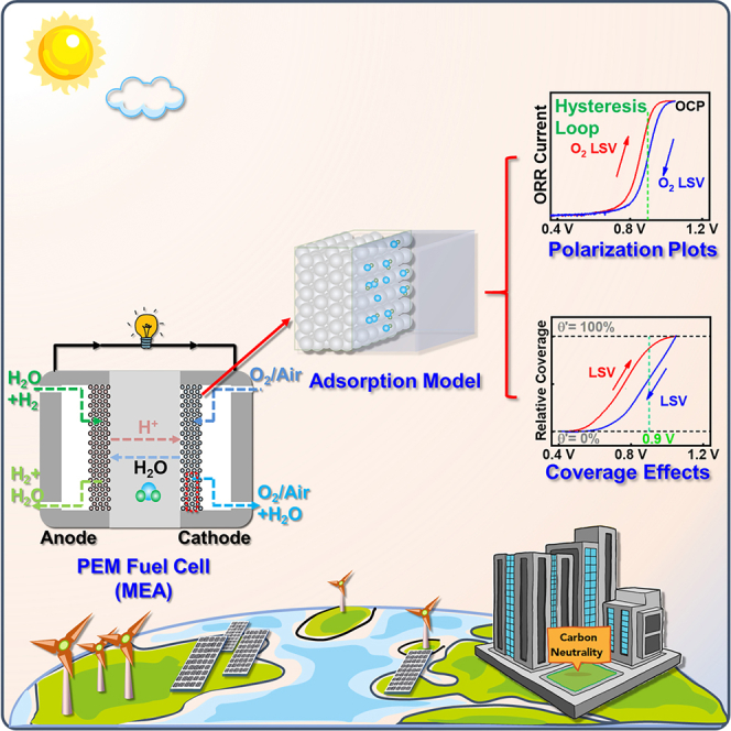
The sluggish oxygen reduction reaction (ORR) has becoming the bottleneck of largescale implementation of proton exchange membrane fuel cells. However, when it comes to the ORR activity assessing of platinum group metals (PGMs) with rotating disk electrode, the corresponding potential conversion vs. reversible hydrogen electrode, test protocols, and activity calculation processes are still in chaos in many published literatures. In this work, two standard calculation processes for PGM ORR activities are demonstrated, followed by a specification for the usage of reference electrodes. Then a 4-fold discrepancy in ORR activities obtained via different test protocols is found for the same Pt/C, and an average adsorption model and the “coverage effects” are proposed to illustrate the hysteresis loop between negative and positive-going ORR polarization plots. Finally, four motions over appropriate assessment of PGM ORR activity are emphasized, hoping to bring a fair communication platform for researchers from different groups.
Subject areas: Chemical reaction, Catalysis, Energy systems, Energy storage
Graphical abstract
Highlights
-
•
Reference electrode usage specifications and mechanisms are illustrated
-
•
A 4-fold ORR activity discrepancy of Pt/C is found for different test protocols
-
•
An average adsorption model with self-consistent iterative algorithm is found
-
•
The coverage effects derived from the model can interpret the ORR hysteresis loop
Chemical reaction; Catalysis; Energy systems; Energy storage
Introduction
Proton exchange membrane fuel cells (PEMFCs) has been regarded as one of the most promising energy technologies to solve the energy crisis and environmental problems (He et al., 2020; Li et al., 2019; Liu et al., 2019; Ma et al., 2020; O'Hayre et al., 2016; Xiong et al., 2020). The last two decades witnesses the vigorous development of PEMFCs technology (Chen et al., 2019; Chong et al., 2018; Li et al., 2016; Paulus et al., 2002; Stamenkovic et al., 2007; Tian et al., 2019; Wang et al., 2013), and roadmaps have been scheduled by governments all over the world to grasp the potential industrial highland of the near future (European Commission, 2020; The Japan METI, 2018; The State Council of China, 2021; The US Department of Energy (DOE), 2016). But the sluggish oxygen reduction reaction (ORR), occurring in the cathode, limits the overall performance and efficiency of PEMFCs, and platinum group metals (PGMs) are the most widely used cathode catalysts as of today for they can achieve an acceptable activity and durability in the acidic and oxidative environments of cathode (Huang et al., 2021; Xu et al., 2020). While PEMFCs is still hindered from its largescale application due to the scarcity and high costs of PGMs (Dong et al., 2020a; Wang et al., 2020a). Great efforts have been paid on catalyst design (Chen et al., 2020a; Hu et al., 2020; Qin et al., 2020; Sandbeck et al., 2020; Zhang et al., 2020a), advanced characterization (Dong et al., 2020b; Wan et al., 2019; Wang et al., 2019c), simulation and theoretical studies (Chen et al., 2020c; Haile et al., 2020; Hammer and Nørskov, 2000; Liu et al., 2020a; Moriau et al., 2021; Nørskov et al., 2004) to get insight into the ORR mechanisms and reduce the Pt loading for PEMFCs. Those achievements, challenges, and prospects of PGMs for ORR during the last twenty years have been well summarized and analyzed by other researchers (Ma et al., 2020; Liu et al., 2020c; Ren et al., 2020; Wang et al., 2019a; Xie et al., 2020). However, when we looked up at those literatures, we found ambiguities in the thin-film rotating disk electrode (TF-RDE) tests (Figure 1) of ORR even in some works of top quality. The details of vital procedures, such as mass/specific activity calculation, potential conversion with respect to reversible hydrogen electrode (RHE) and protocol of ORR polarization tests, are not demonstrated in most published literatures, wherein unexpected variables may be unintentionally introduced, which may bring troubles to beginners and impede the development of PGM catalysts and PEMFCs per se.
Figure 1.

Sketch of typical rotating disk electrode setup (Pine Research, PHYCHEMi, US) for ORR tests
In this work, two standard calculation processes of mass and specific activities are presented, followed by a brief introduction of hydrogen reference electrodes (HREs) and the formation mechanism of liquid junction potential (Ej, originated from the interface of different electrolytes) (Brad and Faulkner, 2000) in practical test system. It should be highlighted even when the Ej term is considered, it will be inappropriate to calculate the potential differences between reference electrodes (REs) with any thermodynamic equation. And a 4-fold discrepancy in ORR activities obtained via different test protocols is found for the same Pt/C catalyst, then an average adsorption model based on minimum necessary assumptions and self-consistent iterative algorithm is established to demonstrate the coverage state of oxygen-containing species on PGM surface. The “coverage effects” derived from the model can interpret the formation mechanism of polarization hysteresis loop (the discrepancy between negative and positive-going ORR polarization plots from ∼0.60 V to ∼1.05 V) very well. At last, the standard potential conversion process, test protocols and activity calculation processes are emphasized to accurate evaluation of ORR performances of PGMs in TF-RDE tests, and the limitation of TF-RDE and its future development are also mentioned. More importantly, we also want to simplify and extend the average adsorption model in later works as an effective and general electrochemical approach to characterize the intrinsic ORR catalytic capabilities of PGMs for electro-catalysis society.
Results
Mass and specific activities and their standard calculation processes
Mass activity (MA), specific activity (SA), and electrochemically active surface area (ECSA) are the fatal indicators describing the performance of PGM catalysts for ORR from different dimensions. MA@0.9V (vs. RHE) is an ultimate activity indicator proposed by the US Department of energy (DOE target of 2025: 0.44 mA/μgPt) (The US Department of Energy (DOE), 2016). and a higher MA means less Pt loading required for certain fuel cell system (<0.1 gPt/kW). ECSA is the exposed surface area of Pt per unit mass determined via hydrogen underpotential deposition (HUPD) or CO stripping (Chen et al., 2010; Vidal-Iglesias et al., 2012), and SA@0.9V derived from MA and ECSA represents the intrinsic activity of catalyst. By now TF-RDE (Figure 1) is the most widely used technique for fast ex situ screening of ORR catalysts because of its convenience and controllability (Chen et al., 2020b; Paulus et al., 2001; Shinozaki et al., 2015a, 2015b; Zhu et al., 2020), and typical test results are presented in Figure 2. Two standard pathways (current pathway: Equations 2.1 and 5.1; current density pathway: Equations 2.2 and 5.2) to calculating MA/SA for PGMs are demonstrated as follows.
| (Equation 1) |
| (Equation 2.1) |
| (Equation 2.2) |
| (Equation 3) |
| (Equation 4) |
| (Equation 5.1) |
| (Equation 5.2) |
JA: the apparent current (mA), JK: the kinetic current (mA), JL: the limiting current (mA), ji: the current densities (mA/cm2); MA: mA/μgPt, MPt: the absolute Pt loading (μgPt), mPt: the Pt loading density (μgPt/cm2), aECSA: the absolute electrochemically active surface area , QH: the integral Faraday charge in hydrogen adsorption region (μC, Figure 2A and 0.05–0.40 V), CDHUPD: the charge density of HUPD, ∼210 μC/cm2 for polycrystalline Pt (Chen et al., 2010), ECSA: , SA: .
Figure 2.

Tests of commercial 20% Pt/C (see characterizations in Figures S4 and S5) on TF-RDE in 0.1 M HClO4 electrolyte
(A) Ar cyclic voltammetry (CV).
(B) ORR polarization tests; Pt loading 10 μgPt, Electrode area 0.2463 cm2.
Simple though calculation processes are, caution should be exercised in the MA and SA calculations because issues could still be found in literatures published in recent years. The possible issues are summarized as follows: (1). The absence of K-L equation, which will lead to a smaller MA or SA. (2). Arithmetic error originating from unit incoherence, for example, a typical ECSA value of should converted to 0.65 before calculation, and different mass activity units (1 mA/μgPt = 1 A/mgPt = 1000 mA/mgPt) are misused by authors, which may cause errors of 1–3 orders of magnitude. (3). Unclear concepts about MA and SA, for instance, incorrect formulas like MA = jK/ECSA, MA = jK/(mPt ×ECSA), MA = jK/MPt, SA = jK/ECSA, and jK = lgjK are adopted. All these could give rise to the inaccuracy of catalyst activity, thus reducing the academic value of article and even making other researchers go astray.
More importantly, from Equation 5.2 (MA = SA×ECSA), we can see the correlation between ECSA, SA, and MA more explicitly. MA is a composite parameter that demonstrates the total apparent catalytic capability of Pt per unit mass, and then SA and ECSA together describe the details of MA from two different aspects. ECSA tells the exposed area of Pt per unit mass, and SA represents the intrinsic catalytic capability (turnover frequency, TOF (Paulus et al., 2002)) of Pt per unit exposed area. Figuratively speaking (Figure 3), a giraffe and an elephant (two different catalysts) may share the same weight (MA), but the giraffe is taller (bigger ECSA) while the elephant is stronger (higher SA). MA (0.44 mA/μgPt@0.9V) is the ultimate goal we pursue for the commercialization of PEMFCs, and ECSA and SA could tell us more details about how to achieve this target.
Figure 3.

Schematic of the correlation between ECSA, SA and MA
Hydrogen reference electrode and potential conversion vs. RHE
As shown in Figure 1, a typical TF-RDE setup usually involves three electrodes, i.e., working electrode (WE), counter electrode (CE) and RE. WE potentials obtained via various REs (like mercury-mercurous sulfate electrode [MSE] (Daudt et al., 2020; Shen et al., 2016), saturated calomel electrode (Fang et al., 2019; Liu et al., 2017), et al.) are usually converted to potentials of RHE scale (Jerkiewicz, 2020; Niu et al., 2020) for the convenience of comparison between different systems. The accuracy of potential conversion is of vital importance for ORR measurement of PGMs, especially with the amplification effect derived from K-L equation (Equation 1 and Figure 1, Figure 2, Figure 3, Figure 4, Figure 5, Figure 6, Figure 7), (Brad and Faulkner, 2000; Paulus et al., 2001) which may finally lead to an error of an order of magnitude on ORR activity. However, the correlation between those electrodes, especially their potential conversion details in practical systems, is not illuminated in most literatures.
Figure 4.

Hydrogen reference electrodes and the comparison between SHE, RHE, and MSE
(A) Hydrogen reference electrodes of “open” and “close” compartment design, Ref (Jerkiewicz, 2020), ACS, reproduced with permission.
(B) Relative potentials of RHE and MSE vs. SHE in electrolytes of different pH (MSE and ORR potentials see Figure S1).
Figure 5.

Calibration of MSE with RHE in HClO4 electrolytes
(A) A typical test device.
(B) Schematic of the formation mechanism of Ej.
(C) Simplified potential profile in test device.
(D) Calibration of MSE with RHE in electrolytes of different pH.
Figure 6.

Effects of test protocol on the ORR performance of commercial Pt/C
(A) Corrected Ar LSVs.
(B) Comparison between negative-going LSV and SCV.
(C) LSV and SCV polarization plots with different scanning directions.
(D) Schematic of adsorption of oxygen-containing spectators on Pt surface in HClO4 (0.40–1.05 V).
Figure 7.

Establishment of average adsorption model
(A) Basic hypotheses.
(B) Self-consistent iterative algorithm to extract pure desorption current from its total current.
(C) Extraction of pure desorption/adsorption currents from Ar LSVs.
(D) Relative coverages (θ′) on Pt/C with different scanning directions (0.40–1.05 V).
Brief history and correlation of HREs
Normal hydrogen electrode (NHE) is a thermodynamically imprecise device developed by researchers in early years for marking the baseline of electric potential, wherein platinum black, monobasic (1 N) strong acid of 1 mol/L, and bubbled H2 of 1 atm are used for the realization of Reaction 1 (Figure 4A (Jerkiewicz, 2020)). While standard hydrogen electrode (SHE), an ideal model with absolute accuracy but cannot be physically attained, is late proposed as the zero point of potential, in which the H+ activity is 1 mol/L and the H2 fugacity (f(H2)) is 1 bar, and its potential is defined as 0 V at arbitrary temperature. One can treat NHE an approximate physical realization of SHE around room temperatures, where the effects of activity/fugacity coefficient and the vapor pressure of water are all neglected. Then RHE is a concept further developed from Equation 6.1, of which the activity and the fugacity of redox couple (H+/H2) are not necessarily in standard states. If we further fix the H2 partial pressure around 1 bar, a simplified Equation 6.2 can be used to calculate the potential of RHE (WikiPedia, 2021; Brad and Faulkner, 2000; Jerkiewicz, 2020; Kamiya, 2013).
| (Reaction 1) |
| (Equation 6.1) |
| (Equation 6.2) |
ϕ0: the standard electrode potential (mV), ϕRHE: the RHE potential vs. SHE (mV), R: the general gas constant (8.314 J mol−1 K−1), T: the absolute temperature (K), F: the Faraday constant (96,485 C/mol), ai: the activity of i species (mol/L), a0: the unit activity (1 mol/L), f(i): the fugacity of i gas (bar), p0: the standard pressure (1 bar).
Figure 4B demonstrates the thermodynamic correlation between different REs with SHE as the zero potential. The green solid point represents the potential of SHE (NHE), while the red solid line of a slope of −59.2 mV/pH and the horizontal magenta solid line in 652 mV stand for the potential of RHE and MSE as a function of pH, respectively. In addition, from Figure 4B we can see that and (all vs. SHE) share the same trend as a function of pH, indicating the effectiveness of comparison (like onset or half-wave potential (Brad and Faulkner, 2000)) between catalysts in electrolytes of different pH, and that is why RHE potential is adopted in the fields like ORR, oxygen evolution reaction (OER), hydrogen evolution reaction, CO2 reduction reaction, nitrogen reduction reaction, and lead acid batteries (Carpente et al., 1996; Jiang et al., 2016; Yan et al., 2019; Zhang et al., 2020b; Zhao et al., 2019).
Calibration of electrode potential with RHE in practical electrolyte
When it comes to the potential conversion of MSE from SHE to RHE in practical system, intuitively, derived from Equations 6 and S1, its mathematical expression could be written as Equation 7 (Wang et al., 2019b).
| (Equation 7) |
| (Equation 8) |
ϕMSE-RHE: the MSE potential vs. RHE in certain electrolyte (mV), ϕMSE: the MSE potential vs. SHE (652 mV), Ej: mV.
However, Equation 7 is thermodynamically right but can only be used for potential calibration when most of Ej could be eliminated (such as the introduction of double salt bridge REs) (Brad and Faulkner, 2000; Carpente et al., 1996; Jerkiewicz, 2020; Niu et al., 2020). A typical test device (Figure 5A) can be used to shed light on the potential conversion issues in practical aqueous solutions. An MSE (652 mV vs. NHE/SHE) is calibrated in 1.0 M HClO4 aqueous solution with a homemade RHE (experimental details in STAR Methods) acting as the RE. Due to the existence of Ej (Figure 5B, the detailed formation mechanism in Figure S2), Ej term should be introduced in the potential conversion equation, as demonstrated in Figure 5C and Equation 8.
Figure 5D demonstrates the discrepancy between thermodynamic values with and without the consideration of Ej (see details in Table S2). The red solid line (ϕTher-RHE) is calculated with Equation 7 and the blue line (ϕTher+Ej-RHE) is derived from Equation 8, while the orange line (ϕExp-RHE) is obtained from the experimental data of MSE calibrated with RHE. A good fitting between thermodynamic and experimental values is achieved after corrections of pH and Ej terms, confirming the effectiveness of introductions of Ej and Henderson equation (Equation S3). However, it does not mean that Equation 8 could be used for potential conversions in practical test systems because REs can’t be stable throughout their service lives (Niu et al., 2020). The potential of stale MSE vs. RHE (ϕStale-RHE) is also calibrated in the same way (green line in Figure 5D), and its deviation from the experimental values of an all-new MSE (blue line) may be attributed to the evolution of chemical compositions inside MSE (like the photocatalytic decomposition of Hg2SO4), (National Center for Biotechnology Information, 2021) meaning MSE should be calibrated with RHE periodically to ensure its reliability.
From the above facts, we can conclude that it will be inappropriate to calculate the potentials of REs or redoxes in WEs vs. RHE with any thermodynamic equations, because Ej and compositional evolutions inside REs can both give rise to unexpected influences to final results. Therefore, we strongly recommend that: (1). RHE with the same electrolyte as bulk solution, whereby Ej will not exist and there is no need to consider the activity coefficient of H+, should be used as RE directly for ORR or other electro-catalyzes (Gong et al., 2019; Kong et al., 2020; Liu et al., 2020b); or (2). Calibrate other REs with RHEs in the test electrolytes just before the tests are performed (Tian et al., 2019; Wang et al., 2018). Only in this way can the impacts derived from Ej and any other uncontrolled aspects from REs per se could be alleviated.
Effects of test protocol on the ORR performance of PGMs
Linear sweep voltammetry (LSV) and staircase voltammetry (SCV) in O2 saturated electrolytes are usually performed on TF-RDE to estimate the ORR catalytic capabilities of PGM-based catalysts, however their subtle distinctions and specific test details are rarely discussed (Ban et al., 2016; Montella, 2017; Paulus et al., 2001; Shinozaki et al., 2015b; Wan et al., 2015). From the potential profiles of LSV and SCV (see also Figure S3), we could know that SCV is a quasi-steady process, wherein the non-faradic current derived from the charging of double-layer could be neglected. While LSV is a semi-steady process, and its capacitive current from double-layer charging (Figure 6A, gained from corrected Ar LSV, and see Figure S7 for details) should be subtracted from its O2 LSV under the same test condition (Brad and Faulkner, 2000). Figure 6B shows the comparison between negative-going original LSV, background-corrected LSV and SCV for commercial Pt/C, and the result shows no obvious difference between negative-going background-corrected LSV and SCV.
Positive-going LSV and SCV, which are also considerably adopted by many researchers for ORR tests, were also performed and the results are presented in Figure 6C. The polarization hysteresis loops are found for both LSV and SCV, especially the ORR MA obtained via positive-going LSV reaches 0.137 mA/ugPt, which is 4 times higher than its negative-going counterpart (see details in Figure 1, Figure 2, Figure 3, Figure 4, Figure 5, Figure 6, Figure 7), and these phenomena are also reported by other researchers (Shinozaki et al., 2015b; Wan et al., 2015). The cathodic current density can be written as Equation 9 (Paulus et al., 2002; Stamenkovic et al., 2007). As all these tests are obtained from one RDE of the same Pt/C, the catalyst per se, the exposed crystalline facets, the applied overpotential, and the mass transport conditions are exactly the same (parameters like k, CO2, a, E, β, and γ in Equation 9 are the same for all tests); thus the discrepancy of ORR polarization plots for negative and positive-going LSVs/SCVs should be attributed to their different coverage degrees (θad) of oxygen-containing species spectators (Figure 6D) on Pt surface (Chen et al., 2020c; Liu et al., 2020c; Paulus et al., 2002; Stamenkovic et al., 2007), as implied by the asymmetric adsorption/desorption currents (from 0.40 V to 1.05 V) in Figure 6A.
| (Equation 9) |
jC: the cathodic current density (mA/cm2), n: the number of electrons (here is 4), e: the elementary charge (1.60 × 10⁻¹⁹ C), k: the rate constant under unit reactants ((mol·L−1)−1·s−1), : the concentration of O2 (mol/L), θad: the absolute coverage degree, a: a constant coefficient, E: the applied potential (V), β and γ: the symmetry factors, rθad: the effects of coverage on the adsorption of adsorbates, SG: the geometric area of electrode (cm2).
To further quantify the coverage effects on the formation of hysteresis loop for negative/positive-going LSVs, an average adsorption model, wherein the species diversity of oxygen-containing spectators adsorbing on Pt surface is ignored, is proposed to calculate the relative coverages (θ′, not the real coverage degree θad, and see definition in Equation S9) of oxygen-containing adsorbates on Pt. It is reasonable to assume the adsorption of negative-going Ar/O2 LSVs before tests are in equilibrium because they were held at 1.05 V (the open-circuit potential [OCP] of the commercial 20% Pt/C) for 60 s, and the negative-going Ar LSV (O2 LSV is too complex) is selected to establish the average adsorption model and demonstrate the adsorption situation of Pt/C between 0.40 and 1.05 V. The basic hypotheses are as follows:
(1) The adsorption state on Pt surface in Ar LSVs are close to those in O2 LSVs, for the adsorption of oxygen-containing spectators is relatively strong (Nørskov et al., 2004; Viswanathan et al., 2012) and thus will not be affected noticeably by ORR; (2) θ′ at 1.05 V and 0.40 V are defined to be 100% and 0%, respectively; (3) The total negative current (J(N), see Figures 7A and 7B) consists of double-layer charging current (JC(N-1)) and desorption current (JD(N)), namely, J(N) = JD(N)+ JC(N-1); (4) The initial oxygen desorption process at ∼1.05 V is slow enough, the initial current pulse around which only corresponds to JC(0), i.e., J(0) = JC(0); (5) There only exists JC(n) at 0.40 V (Brad and Faulkner, 2000) viz,., J(n) = JC(n); (6) The adsorption from 0.40 to 1.05 V is monolayer adsorption and the adsorbate diversity on Pt surface is neglected and averaged (Conway, 1995; Samet et al., 2008), meaning θ′ is a linear function of integrated desorption charge and JC is a linear function of , see details in Figure S10 and Equations S4–S10).
The details of calculation process and its corresponding calculated results are shown in Figures 7B and 7C and Table S5, then the final θ′-potential plots (Figure 7D) is obtained from the pure desorption/adsorption current integrations between 1.05 and 0.40 V in Figure 7C. A sluggish desorption process around 1.05 V and the same hysteresis loop resembling Figure 6C are observed, corroborating the rationality and effectiveness of our model. In addition, from Figure 7D, we could find that the negative-going Ar LSV is accompanied with a sluggish oxygen-containing spectator desorption in high potential regime (>0.9 V) and thus leads to a higher θ' (87.4%) at 0.9 V; while the positive-going Ar LSV is benefited from the sluggish adsorption in low potential regime (<0.9 V) and brings a lower θ' (55.4%), which finally result in the emersion of hysteresis loop between LSVs/SCVs of different scanning directions (Figure 6C and Equation 9).
The effects of scanning potential window and rate (Figures S11–S14), the selection of jL (Figure S15), and the iR-drop correction issues (Figures S16 and S17) are also discussed in supplemental information. Based on the above analyses, we could know that test protocol could have a tremendous impact on PGMs polarization tests. The “coverage effects” along with the amplification effect of K–L equation (Equation 1 and Figure 1, Figure 2, Figure 3, Figure 4, Figure 5, Figure 6, Figure 7) may lead to a 4-fold discrepancy in ORR activities obtained via different test protocols for the same PGM catalyst (PGM-free catalysts like Fe–N–C will not be affected, see discussions in Figures S6 and S9). However, the details of test protocols are rarely mentioned in most published works, which may bring a bit of hassle for the fair comparison between test results from different groups. Since the “coverage effects” also exists in membrane electrode assembly (MEA) in operating conditions and to simulate the standard MEA polarization protocol proposed by DOE (Table S4 (The US Department of Energy (DOE), 2016)), it is highly recommended to adopt reciprocating LSV/SCV (from OCP to 0.05 V, then from 0.05 V back to OCP, as shown in Figure 6C and Figure 1, Figure 2, Figure 3, Figure 4, Figure 5, Figure 6, Figure 7) to assess the activities of PGMs.
Discussion
PEMFCs is of crucial importance to realize the carbon-neutral society for the sustainable development of human kind (Asset and Atanassov, 2020), and enormous advances have been achieved on mechanism study, catalyst synthesis/characterization, MEA simulation/fabrication, and even preliminary commercialization of electric vehicles during the last decade (Deng et al., 2020; E4tech, 2018; Wang et al., 2020b). PGM-based catalysts are still indispensable for the foreseeable largescale application of PEMFCs, nevertheless some fundamental issues concerning potential conversion and activity/durability tests still need to be clarified and standardized for the better development of pivotal ORR catalysts. The following proposals are urgently to be motivated: (1) RHE should be used as RE as far as possible, and if other REs are adopted, their details of potential conversion vs. RHE should be illustrated, and there is no need to conduct iR-drop correction if Luggin capillary is placed correctly in TF-RDE test; (2) To simulate the standard MEA polarization protocol proposed by DOE and narrow the gap of ORR activities obtained via TF-RDE and MEA, reciprocating LSV/SCV should be performed to characterize the ORR performances of PGMs; (3) Connotations like MA and SA should be defined precisely, and K-L equation as well as the selection of jL should be emphasized; (4) The details of calculation processes, such as mPt, jA, jL, and ECSA et al., should be listed in article or supplemental information for the better readability for readers. Furthermore, considering the limited mass transport in TF-RDE and its discrepancy in test conditions with respect to MEA, whose fabrication process is very much an art, floating electrode (Lin et al., 2020; Zalitis et al., 2013) and gas diffusion electrode (Inaba et al., 2018; Mardle et al., 2020; Roudbari et al., 2020) techniques have been proposed in recent years and are under rapid development to bridge the activity gap between TF-RDE and MEA while maintaining its simplicity, convenience, and controllability.
Limitations of the study
In this work, we have emphasized the considerations concerning the appropriate evaluation of PGM ORR catalysts, and 4 motions are proposed hoping to bring a fair communication platform for researchers from different groups. However, those experiments were all conducted on TF-RDE instrument, a general equipment widely taken by researchers for the fast ex situ screening of ORR catalysts but whose environments are different from those in an operating MEA. More efforts and investigations should be done via MEA tests for PGM or PGM-free ORR catalysts, and our laboratory is constructing the MEA test platform right now.
STAR★Methods
Key resources table
| REAGENT or RESOURCE | SOURCE | IDENTIFIER |
|---|---|---|
| Chemicals, peptides, and recombinant proteins | ||
| Commercial 20%Pt/C | Johnson Matthey Fuel Cells | Cat#S128513 |
| Perchloric acid (71 wt.%) | Tianjin Zhengcheng | CAS: 7601-90-3 |
| Nafion Solution (5%) | Macklin | CAS: 31175-20-9 |
| 2-methlimidazole | Shanghai Aladdin | CAS: 693-98-1 |
| Zn(NO3)2·6H2O | Shanghai Aladdin | CAS: 10196-18-6 |
| Fe(NO3)3·9H2O | Shanghai Aladdin | CAS: 7782-61-8 |
| Methanol Anhydrous | Tianjin Tianli | CSA: 170082-17-4 |
| Ethanol Absolute | SinoPharm | CSA: 64-17-5 |
| Deionized Water (18.25 mΩ) | Chengdu Youyue | CSA: 7732-18-5 |
| Software and algorithms | ||
| Origin 2016 | Graphing and data analysis software from OriginLab | https://www.originlab.com/ |
| Office 2016 | Microsoft | https://www.microsoft.com/ |
| Other | ||
| Pine Research MSR Rotator | Pine Research | https://www.pineresearch.com/ |
| Bruker D8 diffractometer | Bruker Corporation | https://www.bruker.com/ |
| JEM-F200 | JEOL | https://www.jeol.co.jp |
Resource availability
Lead contact
Further information and requests for resources should be directed to and will be fulfilled by the lead contact, Zhen-Bo Wang (wangzhb@hit.edu.cn).
Materials availability
This study did not generate new materials.
Method details
Preparation of reversible hydrogen electrode (RHE)
Perchloric acid (HClO4, 71 wt.%) was diluted to aqueous solutions of 3 mol/L, 1 mol/L, 0.3 mol/L, and 0.1 mol/L with DI-water (18.25 mΩ), whose tested pH values are (-0.48), 0.12, 0.58, and 1.06 (Table S1), respectively. Then the prepared solution was injected into a semi-closed cavity of quartz capillary of RHE carefully, followed by a transfer to a beaker with the same HClO4 solution acting as the electrolyte. Then an electrolysis was performed with RHE acting as the anode and Pt mesh electrode acting as the cathode and reference electrode (RE). The potential of RHE was set at -4–-5 V vs. Pt mesh electrode to produce a coherent H2 cylinder inside the RHE quartz capillary (Figure S1). The RHE electrode should stand at least 30 mins to get a stable potential before it could be used as an RHE. In fact, two RHEs were made for each electrolyte of different pH and those two RHEs are calibrated with each other to ensure their reliability.
Calibration of REs with respect to RHE
Two all-new and two stale mercury-mercurous sulfate electrodes (MSEs) were calibrated in HClO4 electrolytes of different pH, and the specific operation is shown in Figure 5A in the main text. The thermodynamic potential of all-new MSE provided by the manufacturer (Tianjin Aida Hengsheng, China) is 652 mV vs. normal hydrogen electrode (NHE).
Synthesis of Fe-N-C PGM-free catalyst
3.39 g Zn(NO3)2·6H2O and 0.10 g Fe(NO3)3·9H2O were dissolved in a conical flask containing 300 mL anhydrous methanol (A solution). 3.94 g 2-methlimidizole was dissolved in a round-bottom flask containing 300 mL anhydrous methanol (B solution). A solution was poured into B solution under vigorous stirring, and the mixed solution was kept at ambient temperature for 20 mins before it was transferred into a thermostat setting at 60 °C. After ∼24 hours, the precipitation was centrifugated and washed with ethanol three times, then the product was dried in a vacuum oven setting at 60 °C overnight. The light yellow material (Fe doped ZIF-8) was ground and then transferred into a furnace with Argon (Ar) protection, followed by a 1050 °C carbonization process for 90 mins. The black powder is marked as Fe-N-C PGM-free catalyst.
Material characterization
The crystal structures were identified by powder X-ray diffraction (XRD) on a Bruker D8 diffractometer with Cu Kα1 X-rays (λ=1.5406 Å). The morphologies and microstructures were observed by a field emission TEM (JEM-F200, 200 kV), equipped with an Oxford EDX detector and a Gatan EELS spectrometer.
The preparation of working electrode (WE)
5 mg of catalyst (Commercial 20% Pt/C or Fe-N-C PGM-free catalyst) was dispensed in a mixed solution (500 μL DI-water + 500 μL ethanol + 30 μL 5% Nafion solution) followed by a 40 mins sonication. The obtained ink was drop-casted on the surface of a pre-polished glassy-carbon electrode (RRDE) and dried under an infrared light for 20 mins to act as a WE. The tests were performed in an electrochemical cell as demonstrated in Figure 1, and Pt mesh and RHE were used as counter electrode (CE) and RE, respectively. The PGM loading is 40.6 μgPt/cm2 for 20% Pt/C; the total loading is 609 μg/cm2 for Fe-N-C PGM-free catalyst.
The Linear sweep voltammetry (LSV) for ORR
The 20%Pt/C WE was activated in Ar saturated 0.1 M HClO4 electrolyte via a cyclic voltammetry test (CV, Ar, 0.05–1.05 V, 100 mV/s, 25 cycles), then an Ar CV test (Ar, 0.05–1.05 V, 50 mV/s, 6 cycles) was performed in the same cell. After that, WE needed to be subjected to an Ar LSV (Ar, Quiet time 60 s, 1.05–0.05 V, 10 mV/s, Sample interval 0.1 mV, 1600 rpm) test beforehand. Then the WE was transferred to another cell with O2 saturated 0.1 M HClO4, and O2 activation and O2 CV were adopted in sequence to make sure the stability of WE. After that, LSV (O2, Quiet time 60 s, 1.05–0.05 V, 10 mV/s, Sample interval 0.1 mV, 1600 rpm) was performed on the WE, and the potential of ring electrode was fixed at 1.20 V. LSVs were performed negatively (negative-going, from 1.05 V to 0.05 V) and positively (positive-going, from 0.05 V to 1.05 V). To ensure the reliability of the test results, two electrodes were used for each test. All tests in this work were performed at ∼25 °C.
The staircase voltammetry (SCV) for ORR
The WE underwent the same Ar activation, Ar CV, O2 activation and O2 CV processes as in LSV test. After that, SCV (O2, Quiet time 60 s, 1.05–0.05 V, Incre E 50 mV, Step period 30 s, 1600 rpm) were performed on the WE, and the potential of ring electrode was fixed at 1.20 V. SCVs were performed negatively (negative-going, from 1.05 V to 0.05 V) and positively (positive-going, from 0.05 V to 1.05 V) for both 20%Pt/C and Fe-N-C PGM-free catalysts.
The hydrogen peroxide yield (H2O2%) calculation
The hydrogen peroxide yield was calculated with the following equation.
Jr: the ring current or current density (mA or mA/cm2), Jd: the disk current or current density (mA or mA/cm2), N: collection coefficient of the RRDE instrument (here is 37%).
Acknowledgments
We acknowledge the National Natural Science Foundation of China (Grant No. 21673064, 51802059, 21905070, and 22075062), China postdoctoral science foundation (Grant No. 2018M631938), Heilongjiang Postdoctoral Fund (LBH-Z18066), and Heilongjiang Touyan Team (Grant No. HITTY-20190033).
Author contributions
Conceptualization, Y.-F. X., P. G., L. Z., X.-L. S., and Z.-B. W.; methodology, Y.-F. X., J.-Z. L., L. Z., X.-L. S., and Z.-B. W.; validation, P. G., J.-Z. L., L. Z., and X.-L. S.; investigation, Y.-F. X. and P. G.; resources, L. Z., X.-L. S., Y. W., and Z.-B. W.; writing-original draft, Y.-F. X.; writing-review & editing, Y.-F. X., J.-Z. L., L. Z., X.-L. S., Y. W., and Z.-B. W.; visualization, Y.-F. X.; supervision and funding acquisition, L. Z., X.-L. S., and Z.-B. W.; project administration, Z.-B. W. All authors reviewed, revised, and approved of this manuscript.
Declaration of interests
The authors declare no competing interests.
Published: September 24, 2021
Footnotes
Supplemental information can be found online at https://doi.org/10.1016/j.isci.2021.103024.
Contributor Information
Lei Zhao, Email: leizhao@hit.edu.cn.
Xu-Lei Sui, Email: suixulei@szu.edu.cn.
Zhen-Bo Wang, Email: wangzhb@hit.edu.cn.
Supplemental information
Data and code availability
All data supporting this study are available in the manuscript and supplemental information.
References
- Asset T., Atanassov P. Iron-nitrogen-carbon catalysts for proton exchange membrane fuel cells. Joule. 2020;4:33–44. doi: 10.1016/j.joule.2019.12.002. [DOI] [Google Scholar]
- Ban Z., Kätelhön E., Compton R.G. Voltammetry of porous layers: staircase vs analog voltammetry. J. Electroanal. Chem. 2016;776:25–33. doi: 10.1016/j.jelechem.2016.06.003. [DOI] [Google Scholar]
- Brad A.J., Faulkner L.R. John Wiley & Sons, Inc.; 2000. Electrochemical Methods: Fundamentals and Applications. [Google Scholar]
- Carpente M.K., Bernardi D.M., Wertz J.A. The use of Hg/Hg2SO4 reference electrodes in valve-regulated lead/acid cells. J. Power Sourc. 1996;63:15–22. doi: 10.1016/S0378-7753(96)02436-6. [DOI] [Google Scholar]
- Chen L., Liu X., Zheng L., Li Y., Guo X., Wan X., Liu Q., Shang J., Shui J. Insights into the role of active site density in the fuel cell performance of Co–N–C catalysts. Appl. Catal. B Environ. 2019;256:117849–117856. doi: 10.1016/j.apcatb.2019.117849. [DOI] [Google Scholar]
- Chen Q.S., Solla-Gullón J., Sun S.G., Feliu J.M. The potential of zero total charge of Pt nanoparticles and polycrystalline electrodes with different surface structure: the role of anion adsorption in fundamental electrocatalysis. Electrochim. Acta. 2010;55:7982–7994. doi: 10.1016/j.electacta.2010.03.050. [DOI] [Google Scholar]
- Chen S., Li M., Gao M., Jin J., van Spronsen M.A., Salmeron M.B., Yang P. High-performance Pt–Co nanoframes for fuel-cell electrocatalysis. Nano Lett. 2020;20:1974–1979. doi: 10.1021/acs.nanolett.9b05251. [DOI] [PubMed] [Google Scholar]
- Chen W., Xiang Q., Peng T., Song C., Shang W., Deng T., Wu J. Reconsidering the benchmarking evaluation of catalytic activity in oxygen reduction reaction. iScience. 2020;23:101532. doi: 10.1016/j.isci.2020.101532. [DOI] [PMC free article] [PubMed] [Google Scholar]
- Chen Y., Cheng T., Goddard W.A., Iii Atomistic explanation of the dramatically improved oxygen reduction reaction of jagged platinum nanowires, 50 times better than Pt. J. Am. Chem. Soc. 2020;142:8625–8632. doi: 10.1021/jacs.9b13218. [DOI] [PubMed] [Google Scholar]
- Chong L.N., Wen J.G., Kubal J., Sen F.G., Zou J.X., Greeley J., Chan M., Barkholtz H., Ding W.J., Liu D.J. Ultralow-loading platinum–cobalt fuel cell catalysts derived from imidazolate frameworks. Science. 2018;362:1276–1281. doi: 10.1126/science.aau0630. [DOI] [PubMed] [Google Scholar]
- Conway B.E. Electrochemical oxide film formation at noble metals as a surface-chemical process. Prog. Surf. Sci. 1995;49:331–452. doi: 10.1016/0079-6816(95)00040-6. [DOI] [Google Scholar]
- Daudt N.F., Poozhikunnath A., Yu H., Bonville L., Maric R. Nano-sized Pt–NbOx supported on TiN as cost-effective electrocatalyst for oxygen reduction reaction. Mater. Renew. Sustain. Energy. 2020;9:18–34. doi: 10.1007/s40243-020-00179-1. [DOI] [Google Scholar]
- Deng X., Zhang J., Fan Z., Tan W., Yang G., Wang W., Zhou W., Shao Z. Understanding and engineering of multiphase transport processes in membrane electrode assembly of proton-exchange membrane fuel cells with a focus on the cathode catalyst layer: a review. Energy Fuels. 2020;34:9175–9188. doi: 10.1021/acs.energyfuels.0c02101. [DOI] [Google Scholar]
- Dong C., Li Y., Cheng D., Zhang M., Liu J., Wang Y.-G., Xiao D., Ma D. Supported metal clusters: fabrication and application in heterogeneous catalysis. ACS Catal. 2020;10:11011–11045. doi: 10.1021/acscatal.0c02818. [DOI] [Google Scholar]
- Dong J.C., Su M., Briega-Martos V., Li L., Le J.B., Radjenovic P., Zhou X.S., Feliu J.M., Tian Z.Q., Li J.F. Direct in situ Raman spectroscopic evidence of oxygen reduction reaction intermediates at high-index Pt(hkl) surfaces. J. Am. Chem. Soc. 2020;142:715–719. doi: 10.1021/jacs.9b12803. [DOI] [PubMed] [Google Scholar]
- E4tech . E4tech; 2018. The Fuel Cell Industry Review 2018. [Google Scholar]
- European Commission Powering a Climate-Neutral Economy: Commission Sets Out Plans for the Energy System of the Future and Clean Hydrogen. 2020. https://ec.europa.eu/commission/presscorner/detail/en/ip_20_1259
- Fang D.H., Wan L., Jiang Q.K., Zhang H.J., Tang X.J., Qin X.P., Shao Z.G., Wei Z.D. Wavy PtCu alloy nanowire networks with abundant surface defects enhanced oxygen reduction reaction. Nano Res. 2019;12:2766–2773. doi: 10.1007/s12274-019-2511-8. [DOI] [Google Scholar]
- Gong M.X., Deng Z.P., Xiao D.D., Han L.L., Zhao T.H., Lu Y., Shen T., Liu X.P., Lin R.Q., Huang T. One-nanometer-thick Pt3Ni bimetallic alloy nanowires advanced oxygen reduction reaction: integrating multiple advantages into one catalyst. ACS Catal. 2019;9:4488–4494. doi: 10.1021/acscatal.9b00603. [DOI] [Google Scholar]
- Haile A.S., Yohannes W., Mekonnen Y.S. Oxygen reduction reaction on Pt-skin Pt3V(111) fuel cell cathode: a density functional theory study. RSC Adv. 2020;10:27346–27356. doi: 10.1039/d0ra02972f. [DOI] [PMC free article] [PubMed] [Google Scholar]
- Hammer B., Nørskov J.K. In: Advances in Catalysis, Vol 45: Impact of Surface Science on Catalysis. Gates B.C., Knozinger H., editors. 2000. Theoretical surface science and catalysis - calculations and concepts; pp. 71–129. [DOI] [Google Scholar]
- He Y.H., Liu S.W., Priest C., Shi Q.R., Wu G. Atomically dispersed metal-nitrogen-carbon catalysts for fuel cells: advances in catalyst design, electrode performance, and durability improvement. Chem. Soc. Rev. 2020;49:3484–3524. doi: 10.1039/c9cs00903e. [DOI] [PubMed] [Google Scholar]
- Hu Y., Jensen J.O., Cleemann L.N., Brandes B.A., Li Q. Synthesis of Pt-rare earth metal nanoalloys. J. Am. Chem. Soc. 2020;142:953–961. doi: 10.1021/jacs.9b10813. [DOI] [PubMed] [Google Scholar]
- Huang L., Zaman S., Tian X., Wang Z., Fang W., Xia B.Y. Advanced platinum-based oxygen reduction electrocatalysts for fuel cells. Acc. Chem. Res. 2021;54:311–322. doi: 10.1021/acs.accounts.0c00488. [DOI] [PubMed] [Google Scholar]
- Inaba M., Jensen A.W., Sievers G.W., Escudero-Escribano M., Zana A., Arenz M. Benchmarking high surface area electrocatalysts in a gas diffusion electrode: measurement of oxygen reduction activities under realistic conditions. Energy Environ. Sci. 2018;11:988–994. doi: 10.1039/c8ee00019k. [DOI] [Google Scholar]
- Jerkiewicz G. Standard and reversible hydrogen electrodes: theory, design, operation, and applications. ACS Catal. 2020;10:8409–8417. doi: 10.1021/acscatal.0c02046. [DOI] [Google Scholar]
- Jiang W.J., Gu L., Li L., Zhang Y., Zhang X., Zhang L.J., Wang J.Q., Hu J.S., Wei Z.D., Wan L.J. Understanding the high activity of Fe–N–C electrocatalysts in oxygen reduction: Fe/Fe3C nanoparticles boost the activity of Fe–Nx. J. Am. Chem. Soc. 2016;138:3570–3578. doi: 10.1021/jacs.6b00757. [DOI] [PubMed] [Google Scholar]
- Kamiya N. Development of an electrolysis-reversible hydrogen electrode (E-RHE) ECS Trans. 2013;50:25–31. doi: 10.1149/05019.0025ecst. [DOI] [Google Scholar]
- Kong Z.J., Maswadeh Y., Vargas J.A., Shan S.Y., Wu Z.P., Kareem H., Leff A.C., Tran D.T., Chang F.F., Yan S. Origin of high activity and durability of twisty nanowire alloy catalysts under oxygen reduction and fuel cell operating conditions. J. Am. Chem. Soc. 2020;142:1287–1299. doi: 10.1021/jacs.9b10239. [DOI] [PubMed] [Google Scholar]
- Li J.Z., Zhang H.G., Samarakoon W., Shan W.T., Cullen D.A., Karakalos S., Chen M.J., Gu D.M., More K.L., Wang G.F. Thermally driven structure and performance evolution of atomically dispersed FeN4 sites for oxygen reduction. Angew. Chem. Int. Ed. 2019;58:18971–18980. doi: 10.1002/anie.201909312. [DOI] [PubMed] [Google Scholar]
- Li M.F., Zhao Z.P., Cheng T., Fortunelli A., Chen C.Y., Yu R., Zhang Q.H., Gu L., Merinov B.V., Lin Z.Y. Ultrafine jagged platinum nanowires enable ultrahigh mass activity for the oxygen reduction reaction. Science. 2016;354:1414–1419. doi: 10.1126/science.aaf9050. [DOI] [PubMed] [Google Scholar]
- Lin X., Zalitis C.M., Sharman J., Kucernak A. Electrocatalyst performance at the gas/electrolyte interface under high-mass-transport conditions: optimization of the "floating electrode" method. ACS Appl. Mater. Inter. 2020;12:47467–47481. doi: 10.1021/acsami.0c12718. [DOI] [PubMed] [Google Scholar]
- Liu J., Jiao M.G., Lu L.L., Barkholtz H.M., Li Y.P., Wang Y., Jiang L.H., Wu Z.J., Liu D.J., Zhuang L. High performance platinum single atom electrocatalyst for oxygen reduction reaction. Nat. Commun. 2017;8:15938–15947. doi: 10.1038/ncomms15938. [DOI] [PMC free article] [PubMed] [Google Scholar]
- Liu M., Zhao Z., Duan X., Huang Y. Nanoscale structure design for high-performance Pt-based ORR catalysts. Adv. Mater. 2019;31:1802234–1802241. doi: 10.1002/adma.201802234. [DOI] [PubMed] [Google Scholar]
- Liu Q., Li Y., Zheng L., Shang J., Liu X., Yu R., Shui J. Sequential synthesis and active-site coordination principle of precious metal single-atom catalysts for oxygen reduction reaction and PEM fuel cells. Adv. Energy Mater. 2020;10:2000689–2000696. doi: 10.1002/aenm.202000689. [DOI] [Google Scholar]
- Liu Z.K., Yin Y.H., Yang D.J., Zhang C.M., Ming P.W., Li B., Yang S.T. Efficient synthesis of Pt–Co nanowires as cathode catalysts for proton exchange membrane fuel cells. RSC Adv. 2020;10:6287–6296. doi: 10.1039/d0ra00264j. [DOI] [PMC free article] [PubMed] [Google Scholar]
- Liu Z.Y., Zhao Z.P., Peng B.S., Duan X.F., Huang Y. Beyond extended surfaces: understanding the oxygen reduction reaction on nanocatalysts. J. Am. Chem. Soc. 2020;142:17812–17827. doi: 10.1021/jacs.0c07696. [DOI] [PubMed] [Google Scholar]
- Ma Z., Cano Z.P., Yu A.P., Chen Z.W., Jiang G.P., Fu X.G., Yang L., Wu T.P., Bai Z.Y., Lu J. Enhancing oxygen reduction activity of Pt-based electrocatalysts: from theoretical mechanisms to practical methods. Angew. Chem. Int. Ed. 2020;59:18334–18348. doi: 10.1002/anie.202003654. [DOI] [PubMed] [Google Scholar]
- Mardle P., Thirunavukkarasu G., Guan S., Chiu Y.-L., Du S. Comparative study of PtNi nanowire array electrodes toward oxygen reduction reaction by half-cell measurement and PEMFC test. ACS Appl. Mater. Inter. 2020;12:42832–42841. doi: 10.1021/acsami.0c11531. [DOI] [PubMed] [Google Scholar]
- Montella C. Further investigation of the equivalence of staircase and linear scan voltammograms. I- Sampling conditions for reversible reactions involving soluble species. J. Electroanal. Chem. 2017;796:96–107. doi: 10.1016/j.jelechem.2017.04.048. [DOI] [Google Scholar]
- Moriau L.J., Hrnjić A., Pavlišič A., Kamšek A.R., Petek U., Ruiz-Zepeda F., Šala M., Pavko L., Šelih V.S., Bele M. Resolving the nanoparticles' structure–property relationships at the atomic level: a study of Pt-based electrocatalysts. iScience. 2021;24:102102. doi: 10.1016/j.isci.2021.102102. [DOI] [PMC free article] [PubMed] [Google Scholar]
- National Center for Biotechnology Information . 2021. PubChem Annotation Record for MERCUROUS SULFATE, Source: Hazardous Substances Data Bank (HSDB) Retrieved August 7, 2021 from https://pubchem.ncbi.nlm.nih.gov/source/hsdb/1206#section=Density. [Google Scholar]
- Niu S., Li S., Du Y., Han X., Xu P. How to reliably report the overpotential of an electrocatalyst. ACS Energy Lett. 2020;5:1083–1087. doi: 10.1021/acsenergylett.0c00321. [DOI] [Google Scholar]
- Nørskov J.K., Rossmeisl J., Logadottir A., Lindqvist L. Origin of the overpotential for oxygen reduction at a fuel-cell cathode. J. Phys. Chem. B. 2004;108:17886–17892. doi: 10.1021/jp047349j. [DOI] [Google Scholar]
- O'Hayre R., Cha S.W., Colella W.G., Prinz F.B. 3rd Edition. John Wiley & Sons, Inc.; 2016. Fuel Cell Fundamentals. [DOI] [Google Scholar]
- Paulus U.A., Schmidt T.J., Gasteiger H.A., Behm R.J. Oxygen reduction on a high-surface area Pt/Vulcan carbon catalyst: a thin-film rotating ring-disk electrode study. J. Electroanal. Chem. 2001;495:134–145. doi: 10.1016/s0022-0728(00)00407-1. [DOI] [Google Scholar]
- Paulus U.A., Wokaun A., Scherer G.G., Schmidt T.J., Stamenkovic V., Radmilovic V., Markovic N.M., Ross P.N. Oxygen reduction on carbon-supported Pt−Ni and Pt−Co alloy catalysts. J. Phys. Chem. B. 2002;106:4181–4191. doi: 10.1021/jp013442l. [DOI] [Google Scholar]
- Qin Y., Zhang W., Guo K., Liu X., Liu J., Liang X., Wang X., Gao D., Gan L., Zhu Y. Fine-tuning intrinsic strain in penta-twinned Pt–Cu–Mn nanoframes boosts oxygen reduction catalysis. Adv. Funct. Mater. 2020;30:1910107–1910114. doi: 10.1002/adfm.201910107. [DOI] [Google Scholar]
- Ren X., Lv Q., Liu L., Liu B., Wang Y., Liu A., Wu G. Current progress of Pt and Pt-based electrocatalysts used for fuel cells. Sustain. Energy Fuels. 2020;4:15–30. doi: 10.1039/c9se00460b. [DOI] [Google Scholar]
- Roudbari M.N., Ojani R., Raoof J.B. Nitrogen functionalized carbon nanotubes as a support of platinum electrocatalysts for performance improvement of ORR using fuel cell cathodic half-cell. Renew. Energy. 2020;159:1015–1028. doi: 10.1016/j.renene.2020.06.028. [DOI] [Google Scholar]
- Samet Y., Mefteh R., Abdelhedi R., Savall A. Improvement of the electrocatalytic activity of platinum in oxidation of aromatic compounds. Comptes Rendus Chim. 2008;11:1254–1261. doi: 10.1016/j.crci.2008.01.003. [DOI] [Google Scholar]
- Sandbeck D.J.S., Secher N.M., Speck F.D., Sørensen J.E., Kibsgaard J., Chorkendorff I., Cherevko S. Particle size effect on platinum dissolution: considerations for accelerated stability testing of fuel cell catalysts. ACS Catal. 2020;10:6281–6290. doi: 10.1021/acscatal.0c00779. [DOI] [Google Scholar]
- Shen L.L., Zhang G.R., Miao S., Liu J., Xu B.-Q. Core–Shell nanostructured Au@NimPt2 electrocatalysts with enhanced activity and durability for oxygen reduction reaction. ACS Catal. 2016;6:1680–1690. doi: 10.1021/acscatal.5b02124. [DOI] [Google Scholar]
- Shinozaki K., Zack J.W., Pylypenko S., Pivovar B.S., Kocha S.S. Oxygen reduction reaction measurements on platinum electrocatalysts utilizing rotating disk electrode technique. J. Electrochem. Soc. 2015;162:F1384–F1396. doi: 10.1149/2.0551512jes. [DOI] [Google Scholar]
- Shinozaki K., Zack J.W., Richards R.M., Pivovar B.S., Kocha S.S. Oxygen reduction reaction measurements on platinum electrocatalysts utilizing rotating disk electrode technique. J. Electrochem. Soc. 2015;162:F1144–F1158. doi: 10.1149/2.1071509jes. [DOI] [Google Scholar]
- Stamenkovic V.R., Fowler B., Mun B.S., Wang G., Ross P.N., Lucas C.A., Marković N.M. Improved oxygen reduction activity on Pt3Ni(111) via increased surface site availability. Science. 2007;315:493–497. doi: 10.1126/science.1135941. [DOI] [PubMed] [Google Scholar]
- The Japan METI Strategic Energy Plan. 2018. https://www.enecho.meti.go.jp/en/category/others/basic_plan/5th/pdf/strategic_energy_plan.pdf
- The State Council of China The Outline of China’s 14th Five-Year Plan (2021-2025) 2021. http://www.gov.cn/zhengce/content/2016-12/19/content_5150090.htm
- The US Department of Energy (DOE) Multi-year research, development, and demonstration plan: Fuel cells section. 2016. http://www.eere.energy.gov/hydrogenandfuelcells/mypp/pdfs/fuel_cells.pdf
- Tian X.L., Zhao X., Su Y.Q., Wang L.J., Wang H.M., Dang D., Chi B., Liu H.F., Hensen E.J.M., Lou X.W.D., Xia B.Y. Engineering bunched Pt–Ni alloy nanocages for efficient oxygen reduction in practical fuel cells. Science. 2019;366:850–856. doi: 10.1126/science.aaw7493. [DOI] [PubMed] [Google Scholar]
- Vidal-Iglesias F.J., Arán-Ais R.M., Solla-Gullón J., Herrero E., Feliu J.M. Electrochemical characterization of shape-controlled Pt nanoparticles in different supporting electrolytes. ACS Catal. 2012;2:901–910. doi: 10.1021/cs200681x. [DOI] [Google Scholar]
- Viswanathan V., Hansen H.A., Rossmeisl J., Nørskov J.K. Universality in oxygen reduction electrocatalysis on metal surfaces. ACS Catal. 2012;2:1654–1660. doi: 10.1021/cs300227s. [DOI] [Google Scholar]
- Wan K., Yu Z.P., Li X.P., Liu M.Y., Yang G., Piao J.H., Liang Z.X. pH effect on electrochemistry of nitrogen-doped carbon catalyst for oxygen reduction reaction. ACS Catal. 2015;5:4325–4332. doi: 10.1021/acscatal.5b01089. [DOI] [Google Scholar]
- Wan X., Liu X., Li Y., Yu R., Zheng L., Yan W., Wang H., Xu M., Shui J. Fe–N–C electrocatalyst with dense active sites and efficient mass transport for high-performance proton exchange membrane fuel cells. Nat. Catal. 2019;2:259–268. doi: 10.1038/s41929-019-0237-3. [DOI] [Google Scholar]
- Wang D.L., Xin H.L.L., Hovden R., Wang H.S., Yu Y.C., Muller D.A., DiSalvo F.J., Abruña H.D. Structurally ordered intermetallic platinum–cobalt core–shell nanoparticles with enhanced activity and stability as oxygen reduction electrocatalysts. Nat. Mater. 2013;12:81–87. doi: 10.1038/nmat3458. [DOI] [PubMed] [Google Scholar]
- Wang X.X., Hwang S.Y., Pan Y.T., Chen K., He Y.H., Karakalos S., Zhang H.G., Spendelow J.S., Su D., Wu G. Ordered Pt3Co intermetallic nanoparticles derived from metal-organic frameworks for oxygen reduction. Nano Lett. 2018;18:4163–4171. doi: 10.1021/acs.nanolett.8b00978. [DOI] [PubMed] [Google Scholar]
- Wang X.X., Sokolowski J., Liu H., Wu G. Pt alloy oxygen-reduction electrocatalysts: synthesis, structure, and property. Chin. J. Catal. 2020;41:739–755. doi: 10.1016/s1872-2067(19)63407-8. [DOI] [Google Scholar]
- Wang X.X., Swihart M.T., Wu G. Achievements, challenges and perspectives on cathode catalysts in proton exchange membrane fuel cells for transportation. Nat. Catal. 2019;2:578–589. doi: 10.1038/s41929-019-0304-9. [DOI] [Google Scholar]
- Wang Y., Ruiz Diaz D.F., Chen K.S., Wang Z., Adroher X.C. Materials, technological status, and fundamentals of PEM fuel cells – a review. Mater. Today. 2020;32:178–203. doi: 10.1016/j.mattod.2019.06.005. [DOI] [Google Scholar]
- Wang Y., Sun D., Chowdhury T., Wagner J.S., Kempa T.J., Hall A.S. Rapid room-temperature synthesis of a metastable ordered intermetallic electrocatalyst. J. Am. Chem. Soc. 2019;141:2342–2347. doi: 10.1021/jacs.8b09919. [DOI] [PubMed] [Google Scholar]
- Wang Y.H., Le J.B., Li W.Q., Wei J., Radjenovic P.M., Zhang H., Zhou X.S., Cheng J., Tian Z.Q., Li J.F. In situ spectroscopic insight into the origin of the enhanced performance of bimetallic nanocatalysts towards the oxygen reduction reaction (ORR) Angew. Chem. Int. Ed. 2019;58:16062–16066. doi: 10.1002/anie.201908907. [DOI] [PubMed] [Google Scholar]
- WikiPedia Standard Hydrogen Electrode. 2021. https://en.wikipedia.org/wiki/Standard_hydrogen_electrode
- Xie C., Niu Z., Kim D., Li M., Yang P. Surface and interface control in nanoparticle catalysis. Chem. Rev. 2020;120:1184–1249. doi: 10.1021/acs.chemrev.9b00220. [DOI] [PubMed] [Google Scholar]
- Xiong Y., Yang Y., DiSalvo F.J., Abruna H.D. Synergistic bimetallic metallic organic framework-derived Pt–Co oxygen reduction electrocatalysts. ACS Nano. 2020;14:13069–13080. doi: 10.1021/acsnano.0c04559. [DOI] [PubMed] [Google Scholar]
- Xu H., Shang H., Wang C., Du Y. Ultrafine Pt-based nanowires for advanced catalysis. Adv. Funct. Mater. 2020;30:2000793–2000810. doi: 10.1002/adfm.202000793. [DOI] [Google Scholar]
- Yan D., Li H., Chen C., Zou Y., Wang S. Defect engineering strategies for nitrogen reduction reactions under ambient conditions. Small Methods. 2019;3:1800331–1800351. doi: 10.1002/smtd.201800331. [DOI] [Google Scholar]
- Zalitis C.M., Kramer D., Kucernak A.R. Electrocatalytic performance of fuel cell reactions at low catalyst loading and high mass transport. Phys. Chem. Chem. Phys. 2013;15:4329–4340. doi: 10.1039/c3cp44431g. [DOI] [PubMed] [Google Scholar]
- Zhang B., Fu G., Li Y., Liang L., Grundish N.S., Tang Y., Goodenough J.B., Cui Z. General strategy for synthesis of ordered Pt3M intermetallics with ultrasmall particle size. Angew. Chem. Int. Ed. Engl. 2020;59:7857–7863. doi: 10.1002/anie.201916260. [DOI] [PubMed] [Google Scholar]
- Zhang X., Wang Y., Gu M., Wang M., Zhang Z., Pan W., Jiang Z., Zheng H., Lucero M., Wang H. Molecular engineering of dispersed nickel phthalocyanines on carbon nanotubes for selective CO2 reduction. Nat. Energy. 2020;5:684–692. doi: 10.1038/s41560-020-0667-9. [DOI] [Google Scholar]
- Zhao Y., Bai J., Wu X.-R., Chen P., Jin P.-J., Yao H.-C., Chen Y. Atomically ultrathin RhCo alloy nanosheet aggregates for efficient water electrolysis in broad pH range. J. Mater. Chem. A. 2019;7:16437–16446. doi: 10.1039/c9ta05334d. [DOI] [Google Scholar]
- Zhu Z., Liu Q., Liu X., Shui J. Temperature impacts on oxygen reduction reaction measured by the rotating disk electrode technique. J. Phys. Chem. C. 2020;124:3069–3079. doi: 10.1021/acs.jpcc.9b10173. [DOI] [Google Scholar]
Associated Data
This section collects any data citations, data availability statements, or supplementary materials included in this article.
Supplementary Materials
Data Availability Statement
All data supporting this study are available in the manuscript and supplemental information.