

Abstract
Vertical femoral neck fractures in patients younger than 65 years of age often require hip‐conserving surgeries. However, traditional fixation strategies using three parallel cannulated screws often fail in such patients due to an unfavorable biomechanical environment. This study compared different cannulated screw fixation techniques in patients via patient‐specific finite element analysis with linear tetrahedral (C3D4) elements. Forty vertical femoral neck fracture models were created based on computed tomography images obtained from eight healthy participants. Five different fixation strategies: alpha, buttress, rhomboid, inverted triangle, and triangle were assessed in walking status. Biomechanical parameters including stiffness, interfragmentary motion in two directions (detachment and shearing), compression force, and maximal implant stress were evaluated. The mean relative coefficient of strain distribution between the finite element analysis and experiment was from 0.78 to 0.94. Stiffness was highest (p < .05) in the buttress group (923.1 N/mm), while interfragmentary motion was lowest (p < .05) in the alpha group. Maximal stress was highest (p < .05) in the buttress group and lowest in the alpha group. Shearing values were significantly lower in the alpha group than in the rhomboid group (p = .004). Moreover, Shearing values were significantly higher (p = .027), while detachment values were significantly lower (p = .027), in the inverted triangle than in the triangle group. Clinical significance: Our results suggest that alpha fixation is the most reliable and biomechanically efficient strategy for young patients with vertical femoral neck fractures. Regular and inverted triangular fixation strategies may be suitable for fractures of different skeletal constructions due to antidetachment/shearing abilities.
Keywords: cannulated screw fixation, interfragmentary motion, patient‐specific finite element analysis, vertical femoral neck fractures
1. INTRODUCTION
Vertical femoral neck fractures in patients younger than 65 years of age often require hip‐conserving surgeries1; however, such procedures remain challenging for orthopedic surgeons due to their high‐energy nature,2 general vulnerabilities in the vasculature,3 and an unfavorable biomechanical environment. Anatomic reduction, thorough stable fixation, and primary healing are necessary for reducing the risk of avascular necrosis and non‐union in these patients. However, the optimal fixation strategy for this fracture type remains controversial.4
According to a web‐based survey conducted in 2014,4 sliding hip screws and cannulated screws are the two most commonly utilized fixation devices for vertical femoral neck fractures. Recently, sliding hip screws have been criticized5, 6 due to their association with an increased risk of osteonecrosis. Thus, cannulated screws remain the most promising and commonly used devices1 because of their minimal invasiveness, easy handling, and ability to induce dynamic compression. Unfortunately, due to the adverse nature of vertical femoral neck fractures, traditional methods utilizing three cannulated parallel screws are associated with high rates of mechanical failure (19%) and osteonecrosis (14%) in patients with Pauwels type III vertical femoral neck fractures.7 Given that these methods are widely accepted amongst surgeons, it remains necessary to identify more efficient screw fixation strategies that can reduce the rates of such complications.
Recently, researchers have successfully modified fixation techniques by adding a fourth screw or augmenting the fixation system with a buttress plate.8, 9 However, few studies have systematically compared biomechanical outcomes among the available fixation methods. To provide guidance for clinical practice, the present study aimed to compare different cannulated screw fixation techniques in patients with vertical femoral neck fractures and to illustrate the detailed biomechanical properties of these techniques via patient‐specific finite element analysis (FEA).
2. MATERIAL AND METHODS
2.1. Models establishment
Eight healthy volunteers ranging in age from 20 to 55 years without any history of hip fracture, metabolic bone disease, or general comorbidities were recruited for the present study (Table 1). Mimics software (Version 19.0; Materialise) was used to develop patient‐specific three‐dimensional (3D) models with a modified Pauwels angle of 70° based on 0.625 mm thick computed tomography (CT) images. The models were then osteotomized using 3‐Matic software (Version 11.0; Materialise). We assessed the effects of five different internal fixation strategies in each model (Figure 1): (1) three inverted parallel screws plus one off‐axis screw, arranged in an “alpha” configuration (group ALP [G‐ALP]); (2) three inverted parallel screws plus one buttress plate strengthening the calcar (G‐BUT); (3) four parallel screws arranged in a “rhomboid” configuration (G‐RHO); (4) three parallel screws with an inverted triangular construction (G‐ITR); (5) three parallel screws with a triangular construction (G‐TRI).
Table 1.
Baseline information
| Patient | Age | Gender | Height (m) | Weight (kg) | BMI (kg/cm2) | HUa | Neck length (mm)b | Neck thickness (mm2)c | NSA |
|---|---|---|---|---|---|---|---|---|---|
| 1 | 29 | F | 1.65 | 50 | 18.37 | 491.66 | 34.21 | 522.13 | 121.76 |
| 2 | 30 | F | 1.55 | 80 | 33.29 | 410.5 | 32.9 | 390.86 | 121.88 |
| 3 | 55 | F | 1.58 | 55 | 22.03 | 435.58 | 38.16 | 586.96 | 126.81 |
| 4 | 21 | M | 1.7 | 70 | 24.22 | 372.94 | 41.57 | 578.96 | 137.31 |
| 5 | 48 | M | 1.73 | 85 | 28.4 | 563.72 | 33.16 | 947.71 | 124.8 |
| 6 | 54 | M | 1.7 | 70 | 24.22 | 409.66 | 34.68 | 789.88 | 122.12 |
| 7 | 30 | M | 1.82 | 100 | 30.19 | 533.36 | 35.15 | 1003.69 | 124.12 |
| 8 | 35 | M | 1.78 | 75 | 23.67 | 581.38 | 35.45 | 928 | 137.55 |
Abbreviations: BMI, body mass index; NSA, femoral neck shaft angle.
Hu indicates average Hu value in the fitted ovoid region of the middle femoral neck. A Hu value above 262 can be used to confirm the absence of osteoporosis according to the previous article.
Neck Length was defined as the distance between femoral head center and femoral neck base along with femora neck axis.
The definition of neck thickness was the area of the narrowest section of femoral neck.
Figure 1.
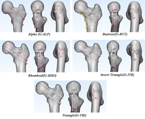
The five groups of fixation models in anterior view, superior view, and lateral view from left to right, including group alpha (G‐ALP), buttress (G‐BUT), rhomboid (G‐RHO), inverted triangle (G‐ITR), triangle (G‐TRI) [Color figure can be viewed at wileyonlinelibrary.com]
To control the essential confounding variable of screw position, all the cannulated screws were implanted according to the same standard criteria, which has been well‐studied and established in previous studies.10, 11, 12, 13, 14 For the parallel cannulated screws, the directions were along the femoral neck axis which was automatically calculated in MATLAB (The MathWorks).15 The parallel screws were positioned dispersedly,10, 11 at 2.5 mm to the cortex of the femoral neck,12, 13 and 5 mm distal to the subchondral bone in the femoral head.14 The off‐axis screw in G‐ALP was implanted at 5 mm proximal to the most prominent part of the great trochanter (to prevent soft tissue irritation due to screw protruding) and targeted at the inferior femoral head‐neck junction (to provide more favorable bone mass for screw purchase).
The constructs were all created in SolidWorks2017 (DS SolidWorks Corp.) using 6.5‐mm cannulated screws (Stryker) and a 6‐hole, 2.7‐mm AO locking plate with 2.7 mm diameter locking screws (Depuy‐Synthes). The locking screws were all fixed using unicortical fixation, and were 30 mm (1st hole), 40 mm (5th hole), and 30 mm (6th hole) in length. Thus, 40 models were generated across the eight participants.
2.2. FEA validation
The donor was 160 cm in height, 50 kg in weight, and absent of any reported musculoskeletal disorders. The pair of cadaver bones harvested from the donor was used in the two‐step experiment of the validation test. All the bones were potted with polymethyl methacrylate 60 mm distal from the lesser trochanter and loaded on the head with 1188.5 N (approximately 237.7% body weight) at an angle of 7° relative to the femur shaft axis16 in the Instron test system (Instron) to simulate the mechanical status during walking17 (Figure 2A). The noncontact strain measurement system, VIC‐3D (XR‐9M; Correlated Solutions Company) was used to record strain distribution at the surface. This system is based on the principles of continuum mechanics18 and can capture consecutive images of the surface of a tested object during the deformation period. Finally, the displacement and strains of the speckles on the surface can be calculated precisely. First, the intact bones were tested mechanically to validate the material assignment method, boundary condition, meshing type, and quality. Then, the bones were osteotomized with a 70° Pauwels angle and fixed with screws in the G‐ITR and G‐ALP configurations separately. To ensure the consistency of the model between the experiment and the simulation, a 3D‐printed guiding plate was applied to ensure the identical position (Figure 2B,C) of the fracture line and cannulated screws. The surgical bones were then tested to validate the assignment of the contact interfaces. Principal strain and interfragmentary motion (IFM) were recorded via VIC‐3D, and used for comparison with FEA results.
Figure 2.

(A) Intact and fixation models were tested under 237.7% body weight with Instron recording the load‐displacement curve and VIC‐3D recording the strain distribution. (B and C) In the validating experiment, the models between finite element analysis and biomechanical experiment were consistent with the help of 3‐D printed guiding and osteotomy templates during surgical process [Color figure can be viewed at wileyonlinelibrary.com]
The FEA models and boundary conditions were established in accordance with the mechanical experiment. Intact and surgical bones were all meshed to 1‐mm equal‐sized facets according to the results of previous mesh convergence tests on similar models19 and checked for quality in Hypermesh 13.0 (Altair Engineering). The models were then meshed with 4‐node linear (C3D4) and second‐order tetrahedron (C3D10) elements separately and were all exported into Abaqus 6.13 (Simulia Corp.) for further FEA. All bone and implant models were assumed to behave with linear elastic properties. The apparent density (ρ), Young's modulus (E), and Poisson's ratio of each element were assigned based on the Hu value in the CT scans according to the following formula,20 which made a distinction between cancellous and cortical bone:
All cannulated screws were assigned as titanium (Ti‐6L‐4V), with Young's modulus (E) of 110,000 MPa and Poisson's ratio of 0.3.21, 22 Thread–bone interfaces were tied while shaft‐bone and fracture interfaces were assigned as slide contact with a frictional coefficient23 of 0.46 and 0.3, respectively (Figure 3A). To simulate the dynamic compression force of the cannulated screws, an extra 224 N preload (Figure 3B) was applied to the middle of the screw shaft using the bolt load in Abaqus software. This was estimated as there are few studies describing the exact value of the preload. Consequently, in our preliminary experiment (Figure 3C), we applied a series of 50, 100, 200, and 300 N bolt loads on cannulated screws during FEA to achieve identical compression forces to that of 6.5 mm Stryker screws from a previous study24 using a linear regression method (Figure 3D).
Figure 3.

The schematic diagram of finite element analysis. (A) Tie contacts (solid arrow) were assigned to thread‐bone, locking screw‐plate, locking screw‐bone junctions, while slide contacts (dotted arrow) were assigned to shaft‐bone, and fracture surface. (B) A 224 N preload was applied first to the cannulated screw, then 237.7% body weight load was applied to the femoral head. (C and D) The finite element analysis model was created in accordance with the boundary conditions in Benjamin's experiment.24 A series of 50, 100, 200, and 300 N bolt loads were exerted on the 6.5‐mm Stryker cannulated screw to find an appropriate value. According to the regression analysis, it was found that a preload of 224 N can generate the same compression force (230 N) in the previous study. (E and F) The schematic diagram of interfragmentary motion (IFM) algorithm. (E) All nodes in the proximal and distal fracture surface were selected for analyzing. The node of the distal fracture surface closest to a selected proximal node was assumed as paired nodes. For each matched node (e.g., P1 and D1) moved to the final position (P2 and D2), the vector of IFM was defined as the displacement of the proximal node relative to the distal node, and the absolute value was used for comparison . (F) IFM was further divided into two components either in the shear direction (shear interfragmentary motion [SIM]) or in the detached direction (detached interfragmentary motion [DIM]) [Color figure can be viewed at wileyonlinelibrary.com]
Strain distribution was compared between FEA and VIC‐3D in intact and osteosynthesis bones. The regions captured by VIC‐3D were automatically matched with the identical regions in FEA using the iterative closest point (ICP) algorithm25 in MATLAB software. The distribution of maximal as well as minimal principal strain, stiffness, and IFM were compared between the simulation and the experiment.
In the preliminary validation test, C3D4 and C3D10 FEA models had a similar mean relative coefficient (C3D4: 0.78–0.94 vs. C3D10: 0.80–0.88) (Figure 4A,B) and the same IFM as well as stiffness tendencies (Figure 4C,D) with the biomechanical experiments. Consequently, FEA with C3D4 elements were sufficient for mechanical comparisons in the present study and were used in the further patient‐specific FEA study.
Figure 4.

Results of the validation experiment. (A and B) Lagrange principal strain of each paired node in finite element analysis (FEA) simulation were all linear correlated with that in VIC‐3D test. (A)The relative coefficients in right and left legs of the same donor were 0.94, 0.88 for C3D4 models, and 0.87, 0.88 for C3D10 models. (B) The relative coefficients in surgical bones were 0.87, 0.78 for C3D4 models, and 0.83, 0.80 for C3D10 models. (C and D) In comparison between G‐ALP and G‐ITR, the tendencies of stiffness and interfragmentary motion were similar between experiment and FEA (both of C3D4 and C3D10) [Color figure can be viewed at wileyonlinelibrary.com]
2.3. Patient‐specific FEA simulation
Following the validation experiment, patient‐specific FEA was performed in all the 40 models with C3D4 meshes using the abovementioned procedure. There were approximately 500,000 elements (from 430,826 to 542,864) and 100,000 nodes (from 93,492 to 117,661) in each model. Additionally, tie contacts were assigned to the plate‐screw and screw‐bone interfaces in the G‐BUT models. All the models were subjected to 237.7% body weight in line with the femoral mechanical axis. Parameters including stiffness, IFM, compression force, and implant stress were comprehensively analyzed. Stiffness was calculated by dividing patient‐specific load by the displacement of the applying node. The IFM of each node was calculated using a previously described formula (Figure 3E)26, 27 and was further decomposed into two components either in the shear direction (shearing interfragmentary motion [SIM]) or detached direction (detachment interfragmentary motion [DIM]) (Figure 3F). Compression force was calculated based on the mean stress in the direction of the normal vector after preloading multiplied by the surface area of the fracture. Data extracted from the FEA were primarily tested for normality using the Kolmogorov–Smirnov test. Randomized block one‐way analysis of variance test was used for comparison among five groups and paired t test was used for comparison between just two groups.
3. RESULTS
In the validation study, we observed a significant linear correlation in the strain distributions between the FEA and VIC‐3D results (p = .000). The mean relative coefficient was 0.94, 0.88 for intact bones and 0.87, 0.78 for surgical bone. The same IFM as well as stiffness tendencies in two fixation groups were observed between the experiment and FEA (Figure 4C,D).
Among the five internal fixation groups, stiffness was highest in G‐BUT (923.1 N/mm), and the lowest IFM value was observed in G‐ALP (Figure 5). Furthermore, IFM values in G‐ALP (0.072 ± 0.031 mm) were significantly (p < .05) lower than those in the G‐RHO, G‐ITR, and G‐TRI groups, while those in G‐BUT (0.080 ± 0.028 mm) were significantly (p < .05) lower than those in G‐ITR and G‐TRI. G‐ALP and G‐BUT were the two most stable techniques in terms of SIM.
Figure 5.

Comparison of stiffness, interfragmentary motion (IFM), shear interfragmentary motion (SIM), and detached interfragmentary motion (DIM) among five groups. G‐BUT were the highest stiffness (923.1 N/mm) devices, while G‐ALP and G‐BUT have similarly lowest IFM, SIM, DIM among these groups [Color figure can be viewed at wileyonlinelibrary.com]
Maximal stress was significantly (p = .000) higher in G‐BUT (776.8 ± 244.6 MPa) than in each of the remaining four groups, while it was lowest in G‐ALP (154.0 ± 40.5 MPa) (Figure 6A). In addition, several sites of stress concentration were detected in G‐BUT, including at the curvature and locking plate‐screw junction (Figure 6B).
Figure 6.
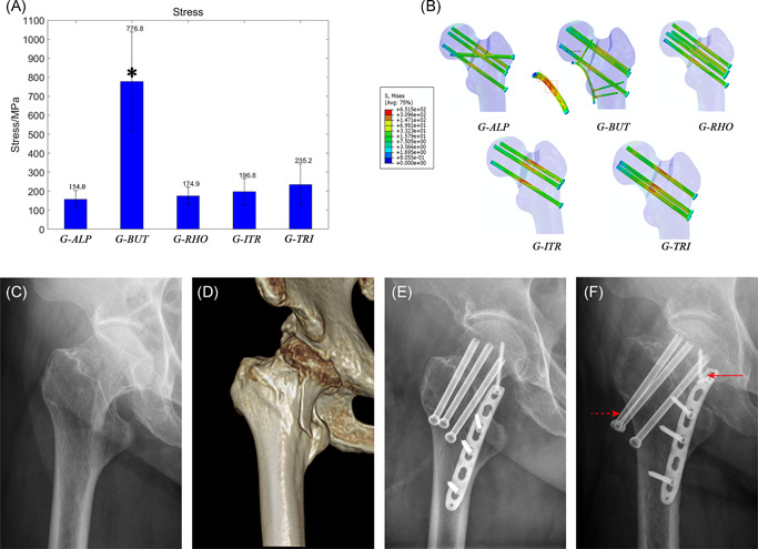
Maximal stress of internal fixation devices. (A) A comparison of maximal stress value of five groups. This value was significantly (p < .05) highest (776.8 + 244.6 MPa) in G‐BUT but lowest (157.4 + 40.5 MPa) in G‐ALP. (B) Von Mises Stress distribution in devices of five groups according to the same gradience. G‐ALP fixation has the smallest high‐stress regions (red color). There are two special stress concentration regions in buttress plate which indicate mechanical pitfall for such strategy. (C and D) Preoperative radiograph of a 64‐year‐old woman showing vertical femoral neck fracture. (E) Radiograph on the second day after this patient was treated with G‐BUT. (fF) Postoperative radiograph approximately 15 months after fixation showed a breakage at the plate‐screw junction (solid arrow), screw withdraw (dotted arrow), and femoral neck shortage. The breakage site was the same as the stress concentration region in our simulation [Color figure can be viewed at wileyonlinelibrary.com]
We then compared the mechanical behavior of the off‐axis screw between G‐ALP and G‐RHO (Figure 7). Our analysis indicated that compression force was significantly lower in G‐ALP than in G‐RHO (p = .008), while DIM values were similar (p = .988). However, IFM (p = .004) and SIM values (p = .004) were also significantly lower in G‐ALP than in G‐RHO.
Figure 7.

A detailed comparison of interfragmentary motion (IFM), shear interfragmentary motion (SIM), detached interfragmentary motion (DIM), and compression force (CF) between G‐RHO and G‐ALP). G‐ALP had significantly lower compression force (p = .008), similar DIM values (p = .988), and significantly lower IFM (p = .004) and SIM values (p = .004) than G‐RHO [Color figure can be viewed at wileyonlinelibrary.com]
We also performed detailed comparisons between G‐ITR and G‐TRI. Overall, stiffness (p = .143) and IFM values (p = .766) were similar between G‐ITR and G‐TRI. However, G‐TRI exhibited significantly lower (p = .027) SIM values, while G‐ITR exhibited significantly higher (p = .027) DIM values. The percentage of IFM difference (ΔIFM%) also exhibited a significant (P = .027) linear correlation with the percentage of DIM (DIM%) (Figure 8A).
Figure 8.

Mechanical differences of regular and invert triangle screws fixation strategies. (A) ΔIFM% ((IFM(G‐TRI) − IFM(G‐ITR))/IFM(G‐ITR))) has a significant (p < .05) linear correlation with DIM% (DIM/IFM), which means that as detached proportion of IFM became larger, the biomechanical benefits of G‐ITR became increasingly prominent. (B) Analysis of the bone structures of the patients suffering from the greatest detached and shear force. The femur on the left has a typically thin femoral neck (390.66 mm2) with the lowest neck‐shaft angle (137.55°) which was better to be fixed by ITR whereas the one on the right has a thick neck (928.00 mm2) with the highest neck‐shaft angle (137.55°) which was better to be fixed by G‐TRI. (C) The derived formula used to demonstrate the phenomenon that the detached force increased as the thickness of femoral neck and the neck‐shaft angle decreasing. M, moment; W, section factor. Note that the angle between anatomic and mechanical femoral axis was assumed as a mean value of 7°. IFM, interfragmentary motion [Color figure can be viewed at wileyonlinelibrary.com]
4. DISCUSSION
In the preliminary validation study, the correlation coefficient (R = 0.78‐0.94) for the results of the FEA and VIC‐3D analyses was satisfactory and within the range of values when compared to previous studies (R = 0.74–0.96).28, 29 The models with C3D4 performed no worse than those with C3D10 in terms of principal strain distribution, showing similar correlation coefficient (R‐value). Quadratic tetrahedral elements (C3D10) modeling can obtain more accurate values owing to denser nodes compared to linear tetrahedral (C3D4), which was confirmed in our test with the value of the slope closer to one. The results of differences between G‐ALP and G‐ITR in stiffness and IFM were the same for the two element types which was consistent with the mechanical experiment. Besides, the C3D4 model has been commonly used in many studies,9, 30, 31, 32 and it was proved to be similar to C3D10 models in accuracy under axial deformation (error: 2.7% vs. 2.8%).33 Consequently, FEA with C3D4 elements were sufficient for mechanical comparisons among different devices under axial loading in the present study.
The present study investigated the biomechanical properties of different cannulated screw fixation strategies for relatively young patients with vertical femoral neck fractures. Our analysis did not reveal a positive relationship between stiffness and IFM. Note that, stiffness is an engineering term that may not accurately reflect stability around the fracture site, whereas reduced IFM may reflect true “stability”34 The latter affects hard callus bridging across the fracture site according to Perren's strain theory, which is directly related to primary bone healing. Unfortunately, previous biomechanical studies have rarely mentioned this parameter,17 which may be difficult to measure accurately with current technologies.
Although our findings indicate that the greatest stability (i.e., least IFM) was achieved in G‐ALP and G‐BUT, significant stress concentration was detected in G‐BUT. Given that no such findings were observed in G‐ALP, this technique may be associated with more desirable biomechanical properties than G‐BUT. In accordance with the results of in vitro biomechanical analyses, augmentation with a buttress plate was associated with the highest stiffness values in our study.8 Most importantly, similarly lowest IFM was observed in the G‐BUT, which may explain the observed improvements in the clinical union rate (89%) when compared with those for traditional methods using three cannulated screws.35 Although buttress plates exhibit an exceptional anti‐shearing ability, few researchers have commented on its outstanding ability to withstand detachment even under an ordinary compression force. The detachment force in the superior part of the fracture surface may be transferred to the plate‐screw junction via the proximal locking screw. This force can also be ascertained based on the residual stress concentration at the plate‐screw junction (Figure 6B). Unfortunately, the stress concentration of the plate‐screw junction represents a major mechanical pitfall of this technique, given that it is associated with an increased risk of breakage and subsequent fixation failure35 (Figure 6C–F). Furthermore, applying a buttress plate may exert detrimental effects on blood supply to the femoral neck due to additional dissection. This may endanger the inferior retinacular artery, which plays an important role in perfusing the femoral head following femoral neck fractures.36, 37 Moreover, application of a buttress plate in patients with femoral neck fractures (especially those with the subcapital type) increases the risk of impingement35, 38 as the hip flexes, potentially leading to significant complications such as osteoarthritis. Given these complications, augmentation using a buttress plate may not be ideal in patients with femoral neck fractures. Nonetheless, buttress plates may be helpful in patients with osteoporotic or comminution when adequate bone purchase and compression force cannot be achieved using cannulated screws.
To further investigate the biomechanical properties at the off‐axis screw, we compared IFM between G‐RHO and G‐ALP, decomposing IFM into shearing (SIM) and detachment (DIM) components. In accordance with previous hypotheses,39, 40 we observed compromised compression force in G‐ALP due to the lack of parallelism, although these decreases in compression force did not compromise DIM in our study. In contrast, anti‐shearing ability was significantly greater in G‐ALP than in G‐RHO, indicating that the biomechanical effect of the off‐axis screw is to improve anti‐shearing stability. This unique biomechanical advantage can be explained as follows: First, the off‐axis screw is more likely to be perpendicular or angulate upward to the fracture plane, which can neutralize the sliding effect6 caused by three angulated parallel screws. Thus, the technique may confront shearing forces more efficiently. Second, bone quality is much better around the calcar than around Ward's triangle of the femoral head, leading to better bone purchase for techniques utilizing an off‐axis screw. Third, the off‐axis screw acts as a lever to transfer the bending moment from the femoral head to the calcar, thereby enhancing cortical support.41 Furthermore, in contrast to the RHO technique, the off‐axis screw used in the ALP technique will not increase stress at the lateral wall, which can reduce the risk of iatrogenic fractures. In accordance with previous findings, the biomechanical properties observed in the present study indicate that techniques utilizing an off‐axis screw are associated with improved union rates and reduced rates of avascular necrosis when compared with traditional techniques utilizing three cannulated screws (Figure 9).41, 42
Figure 9.

Clinical observation of alpha and invert triangle fixation strategies. (A) Preoperative computed topography of a 34‐year‐old female with a Pauwels type‐3 femoral neck fracture. (B) Radiograph on the second day after this patient was treated with traditional three cannulated screw. (C) Postoperative radiograph approximately 14 months after fixation showing non‐union (solid arrow) and screw withdraw (dotted arrow). (D) Preoperative computed topography of another 26‐year‐old male with a vertical femoral neck fracture. (E) Radiograph on the second day after this patient was treated with cannulated screws with an alpha configuration. (F) Radiograph showed fracture union at 13 months postoperatively [Color figure can be viewed at wileyonlinelibrary.com]
In the present study, we also compared mechanical differences between G‐ITR and G‐TRI. As reported in previous studies,43, 44 there were no significant differences in stiffness or IFM between these two groups. However, our detailed biomechanical analysis (Figure 5) revealed that the G‐TRI technique was associated with a greater ability to resist shearing forces, while the G‐ITR technique was associated with a greater ability to resist detachment forces. As expected, the two lag screws placed superiorly and inferiorly are better at resisting tensile and shearing forces, respectively. Further regression analysis revealed the advantages of G‐ITR given increases in SIM and vice versa. Interestingly, we observed that patients with higher detachment forces exhibited typical thin femoral necks (390.66 mm2) with the lowest neck‐shaft angle (NSA) values (121.88°), while those with higher shearing forces exhibited thick femoral necks (928.00 mm2) and the highest NSA values (Figure 8B). This phenomenon can be theoretically demonstrated using the derivation of the cantilever beam formula (Figure 8C), in which the length of the femoral neck exhibits a positive correlation with the maximum tensile stress, while the thickness of the femoral neck and NSA exhibit negative correlations with maximum tensile stress. Generally, for surgeons who still prefer the three‐screw technique due to concerns related to the additional screw's effect on vascular supply, our results suggest that an inverted triangular configuration should be used for patients with a thin femoral neck and lower NSA values, while a regular triangular configuration should be used for patients with a thick femoral neck and higher NSA values. However, further studies are required to verify the validity of this conclusion.
Apart from the abovementioned cannulated screw techniques, dynamic hip screws (DHS) with an anti‐rotational screw are also a common clinical strategy for vertical femoral neck fractures. This device has the advantage of providing angular stability and has been proved to be stiffer than cannulated screws in a previous biomechanical study.45 However, the implantation of DHS is more complicated than cannulated screws and it requires an invasive procedure with dramatic damage to the blood supply, soft tissue dissection, and large bone volume loss. Clinical studies have found a statistically higher operative time, incision size, intraoperative blood loss,46 and subsequently higher avascular necrosis rate5, 6 in DHS compared with cannulated screws. Consequently, cannulated screws with the advantage of being minimally invasive, easy handling, and the ability to induce dynamic compression remain the most promising fixation strategy.
The present study possesses some limitations. First, all models were developed using linear elastic materials and did not incorporate bone plastic deformation or screw loosening processes, which are known to lead to mechanical failure in older patients with osteoporotic fractures. In addition, underestimations of IFM values were attributed to the intact fracture surface and accurate anatomic reduction employed in our models. Our study also focused only on initial stability rather than that during the bone healing process. Furthermore, the thread of the implants was simplified in this study, but it has been proven to have little effect on the outcome.47 Despite these limitations, our findings may aid orthopedic surgeons in selecting the most appropriate fixation strategy in clinical practice.
In conclusion, our findings indicate that the techniques utilized in G‐ALP and G‐BUT provided the most stability with the least IFM in vertical femoral neck fractures. Given its unique biomechanical characteristics, relatively lower implant stress, and decreased likelihood of surgical dissection, G‐ALP may be more reliable than G‐BUT. However, augmentation using a buttress plate may be helpful in patients with comminuted fractures when adequate compression cannot be achieved using fragments alone. A regular triangular screw configuration can be used to ensure maximum anti‐shearing ability and may represent the most appropriate choice for patients with a thick femoral neck and high NSA values, while an inverted triangular configuration may be the most appropriate choice for patients with a thin femoral neck and lower NSA values.
CONFLICT OF INTERESTS
The authors declare that there are no conflict of interests.
ETHICS STATEMENT
CT scanning of participants was approved by the Ethics Committee of Shanghai Sixth People's Hospital (Approval No. 2016‐143) and written consent was obtained from the participant.
AUTHOR CONTRIBUTIONS
Design the study, computational simulation and experimental validation, analysis the results, draft the manuscript: Dajun Jiang. Evaluate the results and technical support, experimental validation, revise the manuscript: Shi Zhan. Provide clinical cases: Lei Wang. Revise the manuscript and language polishing: Lewis L. Shi. Evaluate the results: Ming Ling. Design the study, supervised the study, revise the manuscript: Hai Hu. Design the study, supervised the study, experimental validation, revise the manuscript: Weitao Jia. All authors have read and approved the final submitted manuscript.
Supporting information
Supporting information.
ACKNOWLEDGMENTS
The authors gratefully acknowledge the support of prof. Changqing Zhang, vice director of Shanghai Jiao Tong University affiliated Sixth People's Hospital and Prof. Yimin Chai, the head of Orthopaedic Department of Shanghai Jiao Tong University affiliated Sixth People's Hospital. This investigation was sponsored by the National Key Research and Development Program of China (No. 2018YFC1106300), Shanghai Municipal Education Commission‐Gaofeng Clinical Medicine Grant Support (20172026); Shanghai Talents Development Fund (2017035); Interdisciplinary Program of Shanghai Jiao Tong University (YG2017QN14); Funding project of Shanghai Sixth People's Hospital (ynlc201617).
Jiang D, Zhan S, Wang L, et al. Biomechanical comparison of five cannulated screw fixation strategies for young vertical femoral neck fractures. J Orthop Res. 2021;39:1669–1680. 10.1002/jor.24881
Dajun Jiang and Shi Zhan are first co‐authors.
Weitao Jia and Hai Hu are corresponding co‐authors.
REFERENCES
- 1.Ly TV, Swiontkowski MF. Treatment of femoral neck fractures in young adults. J Bone Joint Surg Am. 2008;90:2254‐2266. [PubMed] [Google Scholar]
- 2.Robinson C, McQueen M, Christie J. Hip fractures in adults younger than 50 years of age. Epidemiology and results. Clin Orthop Relat Res. 1995:238‐246. [PubMed] [Google Scholar]
- 3.Zhao D, Qiu X, Wang B, et al. Epiphyseal arterial network and inferior retinacular artery seem critical to femoral head perfusion in adults with femoral neck fractures. Clin Orthop Relat Res. 2017;475:2011‐2023. [DOI] [PMC free article] [PubMed] [Google Scholar]
- 4.Kevin L, Michael B, Collinge CA. Preoperative decision making in the treatment of high‐angle “vertical” femoral neck fractures in young adult patients. An expert opinion survey of the Orthopaedic Trauma Association's (OTA) membership. J Orthop Trauma. 2014;28:e221–e225. [DOI] [PubMed] [Google Scholar]
- 5.Fixation using Alternative Implants for the Treatment of Hip fractures (FAITH) Investigators . 2017. Fracture fixation in the operative management of hip fractures (FAITH): an international, multicentre, randomised controlled trial. Lancet 389:1519. [DOI] [PMC free article] [PubMed] [Google Scholar]
- 6.Zhang YL, Chen S, Ai ZS, Gao YS, Mei J, Zhang CQ. Osteonecrosis of the femoral head, nonunion and potential risk factors in Pauwels grade‐3 femoral neck fractures:A retrospective cohort study. Medicine. 2016;95:e3706. [DOI] [PMC free article] [PubMed] [Google Scholar]
- 7.Liporace F, Gaines R,C, Haidukewych G. Results of internal fixation of Pauwels type‐3 vertical femoral neck fractures. J Bone Joint Surg Am. 2008;90:1654‐1659. [DOI] [PubMed] [Google Scholar]
- 8.Kunapuli SC, Schramski MJ, Lee AS, et al. Biomechanical analysis of augmented plate fixation for the treatment of vertical shear femoral neck fractures. J Orthop Trauma. 2015;29:144‐150. [DOI] [PubMed] [Google Scholar]
- 9.Tadepalli SC, Erdemir A, Cavanagh PR. Comparison of hexahedral and tetrahedral elements in finite element analysis of the foot and footwear. J Biomech. 2011;44:2337‐2343. [DOI] [PMC free article] [PubMed] [Google Scholar]
- 10.Mei J, Liu S, Jia G, Cui X, Jiang C, Ou Y. Finite element analysis of the effect of cannulated screw placement and drilling frequency on femoral neck fracture fixation. Injury. 2014;45:2045‐2050. [DOI] [PubMed] [Google Scholar]
- 11.Zdero R, Keast‐Butler O, Schemitsch EH. A Biomechanical comparison of two triple‐screw methods for femoral neck fracture fixation in a synthetic bone model. J Trauma. 2010;69:1537‐1544. [DOI] [PubMed] [Google Scholar]
- 12.Lindequist S. Cortical screw support in femoral neck fractures: a radiographic analysis of 87 fractures with a new mensuration technique. Acta Orthop Scand. 1993;64:289‐293. [DOI] [PubMed] [Google Scholar]
- 13.Lindequist S, Törnkvist H. Quality of reduction and cortical screw support in femoral neck fractures. An analysis of 72 fractures with a new computerized measuring method. J Orthop Trauma. 1995;9:215‐221. [DOI] [PubMed] [Google Scholar]
- 14.Jensen C, Mainz H, Lamm M. Referenceprogram for patienter med hoftebrud. København: Dansk Sygeplejeråd, Danske Fysioterapeuter, Dansk Ortopædisk Selskab; 2008.
- 15.Dimitriou D, Tsai TY, Yue B, Rubash HE, Kwon YM, Li G. Side‐to‐side variation in normal femoral morphology: 3D CT analysis of 122 femurs. Orthop Traumatol Surg Res. 2016;102:91‐97. [DOI] [PubMed] [Google Scholar]
- 16.Zhang B, Liu J, Zhu Y, Zhang W. A new configuration of cannulated screw fixation in the treatment of vertical femoral neck fractures. Int Orthop. 2018;42:1949‐1955. [DOI] [PubMed] [Google Scholar]
- 17.Heller MO, Bergmann G, Kassi JP, Claes L, Haas NP, Duda GN. Determination of muscle loading at the hip joint for use in pre‐clinical testing. J Biomech. 2005;38:1155‐1163. [DOI] [PubMed] [Google Scholar]
- 18.Chu TC, Ranson WF, Sutton MA. Applications of digital‐image‐correlation techniques to experimental mechanics. Exp Mech. 1985;25:232‐244. [Google Scholar]
- 19.Hölzer A, Schröder C, Woiczinski M, et al. Subject‐specific finite element simulation of the human femur considering inhomogeneous material properties: a straightforward method and convergence study. Comput Methods Programs Biomed. 2013;110:82‐88. [DOI] [PubMed] [Google Scholar]
- 20.Reina‐Romo E, Rodríguez‐Vallés J, Sanz‐Herrera JA. In silico dynamic characterization of the femur: physiological versus mechanical boundary conditions. Med Eng Phys. 2018;58:80‐85. [DOI] [PubMed] [Google Scholar]
- 21.Fan Y, Xiu K, Duan H, Zhang M. Biomechanical and histological evaluation of the application of biodegradable poly‐l‐lactic cushion to the plate internal fixation for bone fracture healing. Clin Biomech. 2008;23:S7‐S16. [DOI] [PubMed] [Google Scholar]
- 22.Benli S, Aksoy S, Havıtcıoğlu H, Kucuk M. Evaluation of bone plate with low‐stiffness material in terms of stress distribution. J Biomech. 2008;41:3229‐3235. [DOI] [PubMed] [Google Scholar]
- 23.Eberle S, Gerber C, von Oldenburg G, Högel F, Augat P. A biomechanical evaluation of orthopaedic implants for hip fractures by finite element analysis and in‐vitro tests. Proc Inst Mech Eng H. 2010;224:1141‐1152. [DOI] [PubMed] [Google Scholar]
- 24.Watson BC, Taylor BC, Madsen A, Persinger FD, Malarkey AR. Biomechanical evaluation of 6.5‐mm cannulated screws. J Surg Orthop Adv. 2016;25:8. [PubMed] [Google Scholar]
- 25.Besl PJ, McKay ND. A method for registration of 3‐D shapes. IEEE Trans Pattern Anal Mach Intell. 1992;14:239‐256. [Google Scholar]
- 26.Samsami S, Saberi S, Bagheri N, Rouhi G. Interfragmentary motion assessment for three different fixation techniques of femoral neck fractures in young adults. Biomed Mater Eng. 2016;27:389‐404. [DOI] [PubMed] [Google Scholar]
- 27.Samsami S, Augat P, Rouhi G. Stability of femoral neck fracture fixation: a finite element analysis. Proc Inst Mech Eng H. 2019;233:892‐900. [DOI] [PubMed] [Google Scholar]
- 28.Dubov A, Kim SYR, Shah S, Schemitsch EH, Zdero R, Bougherara H. The biomechanics of plate repair of periprosthetic femur fractures near the tip of a total hip implant: the effect of cable‐screw position. Proc Inst Mech Eng H. 2011;225:857‐865. [DOI] [PubMed] [Google Scholar]
- 29.Ebrahimi H, Rabinovich M, Vuleta V, et al. Biomechanical properties of an intact, injured, repaired, and healed femur: an experimental and computational study. J Mech Behav Biomed Mater. 2012;16:121‐135. [DOI] [PubMed] [Google Scholar]
- 30.Machado MM, Fernandes PR, Zymbal V, Baptista F. Human proximal femur bone adaptation to variations in hip geometry. Bone. 2014;67:193‐199. [DOI] [PubMed] [Google Scholar]
- 31.Ni M, Wong DWC, Niu W, Wang Y, Mei J, Zhang M. Biomechanical comparison of modified Calcanail system with plating fixation in intra‐articular calcaneal fracture: a finite element analysis. Med Eng Phys. 2019;70:70‐61. [DOI] [PubMed] [Google Scholar]
- 32.Ni M, Niu W, Wong DWC, Zeng W, Mei J, Zhang M. Finite element analysis of locking plate and two types of intramedullary nails for treating mid‐shaft clavicle fractures. Injury. 2016;47:1618‐1623. [DOI] [PubMed] [Google Scholar]
- 33.Raut P. Impact of mesh quality parameters on elements such as beam, shell and 3D solid in structural analysis. Int J Eng Res Appl. 2012;2:99‐103. [Google Scholar]
- 34.Rüedi TP, Murphy WM. AO principles of fracture management: Thieme; 2017.
- 35.Ye Y, Chen K, Tian K, Li W, Mauffrey C, Hak DJ. Medial buttress plate augmentation of cannulated screw fixation in vertically unstable femoral neck fractures: surgical technique and preliminary results. Injury. 2017;48:2189‐2193. [DOI] [PubMed] [Google Scholar]
- 36.Boraiah S, Dyke JP, Hettrich C, et al. Assessment of vascularity of the femoral head using gadolinium (Gd‐DTPA)‐enhanced magnetic resonance imaging: a cadaver study. J Bone Joint Surg Br. 2009;91:131‐137. [DOI] [PubMed] [Google Scholar]
- 37.Lazaro LE, Sculco PK, Pardee NC, et al. Assessment of femoral head and head‐neck junction perfusion following surgical hip dislocation using gadolinium‐enhanced magnetic resonance imaging: a cadaveric study. J Bone Joint Surg Am. 2013;95:1821‐1828. [DOI] [PubMed] [Google Scholar]
- 38.Marchand LS, Karns M, Higgins TF, Aoki SK. Femoral neck fracture fixation with a medial buttress plate that led to impingement with hip flexion: a case report. JBJS Case Connector. 2019;9:e21. [DOI] [PubMed] [Google Scholar]
- 39.Kyle RF. Operative techniques of fixation for femoral neck fractures in young adults. Tech Orthop. 1986;1:33‐38. [Google Scholar]
- 40.Duffin M, Pilson HT. Technologies for young femoral neck fracture fixation. J Orthop Trauma. 2019;33:S20‐S26. [DOI] [PubMed] [Google Scholar]
- 41.Dong Q, Han Z, Zhang YG, Sun X, Ma XL. Comparison of transverse cancellous lag screw and ordinary cannulated screw fixations in treatment of vertical femoral neck fractures. Orthop Surg. 2019;11:11‐603. [DOI] [PMC free article] [PubMed] [Google Scholar]
- 42.Jam GE, Rocha LR, Noronha Rocha TH, et al. Vertical femoral neck fractures in young adults: a closed fixation strategy using a transverse cancellous lag screw. Injury. 2017;48(suppl 4):S10. [DOI] [PubMed] [Google Scholar]
- 43.Selvan VT, Oakley MJ, Rangan A, Al‐Lami MK. Optimum configuration of cannulated hip screws for the fixation of intracapsular hip fractures: a biomechanical study. Injury. 2004;35:136‐141. [DOI] [PubMed] [Google Scholar]
- 44.Oakey JW, Stover MD, Summers HD, Sartori M, Havey RM, Patwardhan AG. Does screw configuration affect subtrochanteric fracture after femoral neck fixation? Clin Orthop Relat Res. 2006;443:302‐306. [DOI] [PubMed] [Google Scholar]
- 45.Nowotarski PJ, Ervin B, Weatherby B, Pettit J, Goulet R, Norris B. Biomechanical analysis of a novel femoral neck locking plate for treatment of vertical shear Pauwel's type C femoral neck fractures. Injury. 2012;43:802‐806. [DOI] [PubMed] [Google Scholar]
- 46.Gupta M, Arya RK, Kumar S, Jain VK, Sinha S, Naik AK. Comparative study of multiple cancellous screws versus sliding hip screws in femoral neck fractures of young adults. Chin J Traumatol. 2016;19:209‐212. [DOI] [PMC free article] [PubMed] [Google Scholar]
- 47.Inzana JA, Varga P, Windolf M. Implicit modeling of screw threads for efficient finite element analysis of complex bone‐implant systems. J Biomech. 2016;49:1836‐1844. [DOI] [PubMed] [Google Scholar]
Associated Data
This section collects any data citations, data availability statements, or supplementary materials included in this article.
Supplementary Materials
Supporting information.