

Abstract
Aims
To illustrate the practical and technical challenges along with the safety aspects when performing MRI‐guided electrophysiological procedures in a pre‐existing diagnostic magnetic resonance imaging (MRI) environment.
Methods and Results
A dedicated, well‐trained multidisciplinary interventional cardiac MRI team (iCMR team), consisting of electrophysiologists, imaging cardiologists, radiologists, anaesthesiologists, MRI physicists, electrophysiological (EP) and MRI technicians, biomedical engineers, and medical instrumentation technologists is a prerequisite for a safe and feasible implementation of CMR‐guided electrophysiological procedures (iCMR) in a pre‐existing MRI environment. A formal dry run “mock‐up” to address the entire spectrum of technical, logistic, and safety issues was performed before obtaining final approval of the Board of Directors. With this process we showed feasibility of our workflow, safety protocol, and bailout procedures during iCMR outside the conventional EP lab. The practical aspects of performing iCMR procedures in a pre‐existing MRI environment were addressed and solidified. Finally, the influence on neighbouring MRI scanners was evaluated, showing no interference.
Conclusion
Transforming a pre‐existing diagnostic MRI environment into an iCMR suite is feasible and safe. However, performing iCMR procedures outside the conventional fluoroscopic lab, poses challenges with technical, practical, and safety aspects that need to be addressed by a dedicated multi‐disciplinary iCMR team.
Keywords: basic: atrial fibrillation/atrial arrhythmias, clinical: cardiac anatomy, clinical: catheter ablation–atrial flutter, clinical: electrophysiology–atrial arrhythmias, clinical: noninvasive techniques–MRI
1. INTRODUCTION
Since the development of real‐time magnetic resonance imaging (MRI)‐guided electrophysiology, its feasibility has been demonstrated in multiple preclinical and clinical studies.1, 2, 3, 4, 5 The promising study results and growing availability of MR compatible CE‐approved electrophysiological (EP) equipment, including mapping catheters and ablation systems, have accelerated the clinical implementation of interventional cardiac MRI (iCMR) procedures worldwide. Dedicated iCMR suites have been built with X‐ray and MRI systems installed in adjacent rooms to facilitate a hybrid approach. However, the steadily increasing experience and safety of iCMR procedures disputes the necessity for additional X‐ray and fluoroscopic guidance. Translocating the iCMR procedure to a pre‐existing standard MRI room may be a superior solution from a practical, logistical, and potentially financial point of view. In this manuscript, we describe the technical and practical challenges, material requirements, and safety aspects of transforming a pre‐existing MRI environment into an iCMR suite.
2. PART I: THE FRAMEWORK OF THE OLD STATE
Conventional EP interventions are routinely executed in a specialized EP lab, using fluoroscopy as imaging modality to guide catheter insertion and placement. The harmful X‐ray radiation of fluoroscopy requires the use of lead‐lined personal protective equipment. Additionally, echocardiography equipment is regularly present to guide vascular access and interatrial septal puncture when indicated. Emergency equipment, including a crash car and defibrillator, are present for potential life‐threatening situations that can occur. Throughout the EP lab, a large spectrum of electrical equipment is used, including monitors, stimulators, an RF generator, electro‐anatomical mapping system, cables, and various patient monitoring systems. Generally, this equipment is not designed to operate in an MRI environment using a strong magnetic field, and thus labelled as non‐MR compatible as standard.
MRI examinations are performed using a system that generates a large magnetic field and uses magnetic field gradients and electromagnetic radio waves to obtain images. This MRI scanner is installed inside a so‐called Faraday cage made of a copper mesh to prevent external electromagnetic fields from entering the scanner room. Special doors that are sealed by a set of electrical contact strips, to avoid RF leakage when closed, are used to provide access to the scanner room. Waveguides are used to guide fiber optic cables and/or infuse extension lines from the scanner room through the Faraday cage to the MRI control room and vice versa. The American College of Radiology defines four different MRI zones with specific access restrictions and safety considerations.6 MRI zone 1 and 2 are areas accessible to the public, such as the waiting room areas and corridors. MRI zone 3 consists of the MRI control room and the patient preparation zone. Finally, MRI zone 4 is the restricted area where the MRI system is located and in which the static magnetic field is critically high with an imminent projectile risk of ferromagnetic materials. MRI zone 3 and 4 must be strictly controlled by certified MRI staff to prevent safety hazards. As an example, Figure 1 illustrates the physical layout of the MRI suite at the Maastricht University Medical Center with the four different MRI zones.
Figure 1.
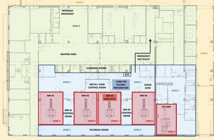
Floor plan of the pre‐existing MRI environment at the Maastricht University Medical Center illustrating the four different MRI zones. MRI, magnetic resonance imaging
3. PART II: THE DEMANDS OF THE NEW STATE—PREREQUISITES FOR THE TRANSFORMATION TO AN ICMR SUITE
When transforming a pre‐existing MRI environment into an iCMR suite, the new environment needs to meet the hygienic and technical standards that follow both MRI and surgical guidelines.
3.1. Hygienic standards
An iCMR suite requires high hygienic standards to minimize periprocedural infections and should therefore meet the criteria of an OR class 2 facility.7 Hygienic recommendations include (1) sufficient air circulation with air renewal at least six times per hour, (2) implementation of a high‐efficiency particulate air (HEPA)‐filter, (3) air quality according to ISO class 7, and (4) a room temperature of 18–23° Celsius. In our iCMR suite air renewal of 20 times an hour is established by the following settings: airflow 2200 m3/hour, airspeed 3.4 m/s, ventilation multiplier 20. Another hygienic aspect is access control. A high volume of “foot traffic” influences air turbulence and thus sterility, as well as increases the risk of bringing ferromagnetic objects into MRI zone 4. Foot traffic can be minimized by entrance restrictions and visible markings at the doors to MRI zone 3 and 4. Instructions on personal hygiene and careful cleaning and disinfection of the environment should be an integral part of periodic staff training.
3.2. Electrical system modifications
The electrical installation of a pre‐existing MRI environment most probably requires modifications to comply with safety guidelines required for iCMR procedures. International guidelines distinguish different classifications: a standard MRI scanner room has a K2 classification, while an iCMR suite requires a G2 classification.8 The G2 classification requires a touch‐voltage less than 10 mV, isolation transformers for all wall power outlets, and a ‘protected earth' connection for every device. The electrical system can only be re‐certified after installation of the complete setup as every (subset of a) device generates its own leak voltage. After fulfilling and evaluating all requirements, a recertification of the rooms can be granted to allow for iCMR procedures. Figure 2 illustrates the full transformation of the pre‐existing MRI environment into the iCMR suite in our center.
Figure 2.
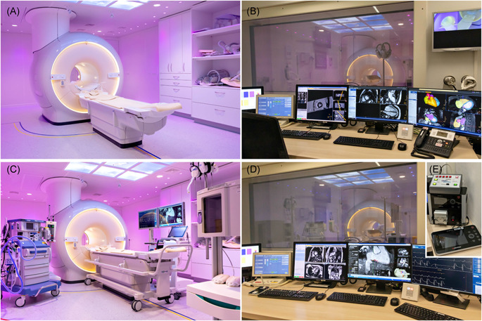
Full transformation of the pre‐existing MRI environment into an interventional cardiac MRI suite. (A) pre‐existing diagnostic MRI scanner room. (B) pre‐existing diagnostic MRI control room. (C) transformed iCMR suite (from left to right: anesthetic equipment, contrast pump, MR scanner with transportable tabletop, two movable displays (left EP recordings, right real‐time MR imaging/active catheter tracking), patient vitals monitor, wireless communication headsets, MR safe anesthetic infusion pump cabinet). (D) transformed iCMR control room (the two right monitors correspond to the displays inside the iCMR suite). (E) the non‐MR compatible RF generator including cooling‐pump positioned in the iCMR control room. EP, electrophysiological; iCMR, interventional cardiac MRI; MRI, magnetic resonance imaging
3.3. Equipment decisions
The installation of additional iCMR specific hardware and software requires technical modifications to ensure integration with the pre‐existing systems. The number of vendors offering commercially available iCMR equipment is limited given the novelty of iCMR technology.
The following materials are essential for performing iCMR:
-
‐
MR compatible EP recording system.
-
‐
MR compatible EP catheters (e.g., ablation catheter and a mapping catheter, with or without the possibility for active catheter tracking).
-
‐
RF generator including cooling‐pump (not MR compatible, placed in the iCMR control room)
-
‐
MR compatible displays for real‐time viewing inside the iCMR suite.
-
‐
MR compatible anesthetic equipment for patient sedation.
-
‐
Imaging software for either real‐time MR scanning (when using passive tracking) or catheter tracking (when using active tracking)
-
‐
MR compatible headsets for communication between the iCMR suite and its control room.
3.4. Magnetic field safety
MRI scanners generate a very large magnetic field that is not only present inside the MRI scanner itself, but also throughout most of the scanner room. This magnetic field causes strong attractional and rotational forces for all ferromagnetic objects, potentially turning these into deadly projectiles when brought into the scanner room (zone 4). Where possible, all standard EP and anesthetic instruments should therefore be replaced with non‐ferromagnetic alternatives to avoid this projectile risk and ensure both patient and personnel safety. All items should be labelled either MR safe or MR conditional before being transported (partly) into zone 4.6 Ferromagnetic instruments that cannot be replaced shall be clearly labelled as MR unsafe and should therefore stay in zone 3 at all times. For example, a non‐MR compatible RF generator is positioned in the iCMR control room and operated by the EP technician. Additionally, ultrasound‐guided cannulation of the femoral vein, intubation with a laryngoscope, and electrical cardioversion (if indicated) must be performed in MRI zone 3.
4. PART III: THE TRANSFORMATION—ICMR PROCEDURAL WORKFLOW AND SAFETY ISSUES
4.1. Dedicated multidisciplinary iCMR team and protocol development
A dedicated, well‐trained multidisciplinary iCMR team is a prerequisite for a safe and feasible implementation of iCMR. This iCMR team should be a closely collaborating group of electrophysiologists, radiologists, imaging cardiologists, anesthesiologist, MRI physicists, EP and MRI technicians, biomedical engineers, and medical instrumentation technologists. This multidisciplinary collaboration is of utmost importance to bridge the gap between the pre‐existing workflows of radiological teams and interventional EP teams. To streamline the procedure and ensure safety for both patients and staff, we advise to develop the following documents: (1) iCMR procedural workflow, and (2) general safety protocol. Formats for these documents are presented in Supplementary Appendix A and B. Joint participation in mock‐up procedures is essential for safe clinical implementation of iCMR, and often required by the Board of Directors. Furthermore, such a new approach requires a solid financial plan. In our hospital, financial analyses showed that the costs of MR compatible disposable tools were comparable to those used for conventional EP procedures, and no additional reimbursement was deemed necessary. The technical modifications of the existing MRI environment and purchase of non‐disposable iCMR equipment were a one‐off investment for this innovative treatment. The total expenses on the long term, however, will depend on national, local, and interdisciplinary agreements. Current clinical research in our hospital will provide further insight in the cost‐effectiveness of performing iCMR procedures in a transformed pre‐existing MRI environment as part of clinical patient care.
4.2. iCMR procedural workflow
A possible format for an operational iCMR procedural workflow is presented in Supplementary Appendix A. It was built around five key aspects: (1) iCMR suite preparation, (2) patient preparation outside the iCMR suite, in the adjacent patient preparation zone, (3) safe transfer of patient to the iCMR suite, (4) complete and safe performance of the iCMR procedure, and (5) awareness of potential complications. Preparation of the iCMR suite consists of the placement and installation of the required equipment. Patient preparation in the adjacent patient preparation zone consists of patient identification and a ‘time‐out procedure', followed by general anesthesia induction (or sedation), electrical cardioversion (if required), sterile draping of the patient and vascular access to the femoral vein. After definite removal of all MR unsafe material, the patient is transferred to the iCMR suite. After placement of the patient inside the MRI scanner, sterility is completed by draping the MRI scanner. The iCMR procedure then commences with baseline MR imaging, followed by the insertion of the catheters and execution of the EP procedure with CMR guidance.9 General anesthesia is maintained throughout the procedure. After completion of the ablation procedure, MR imaging is performed to exclude complications (e.g., pericardial effusion). Additionally, when indicated, during the required waiting time following the EP procedure CMR can be used to evaluate tissue characterization at the target location before and after RF ablation. After removal of the catheters, the patient is removed from the MRI suite to the adjacent patient preparation zone. Here general anesthesia is stopped, the patient is detubated, and the vascular access is removed. Finally, the patient can be transferred to the post‐anesthetic care unit for recovery.
4.3. Safety issues
All iCMR team members should be educated on potential safety hazards of the MRI environment. Since MRI utilizes high static magnetic fields that are present 24/7, even when the MRI system is not in use, life‐threatening situations can occur when staff is insufficiently trained and when MR safety protocols are absent. Consistent and repetitive training of the iCMR team, as well as safety briefings before each procedure. Specific safety measures are crucial to avoid potential hazards to either the patient, the staff or both.
-
‐
PATIENT ELIGIBILITY should be confirmed in the outpatient clinic by the referring clinician and before the procedure by an MRI contraindication safety checklist. Patients are screened for ferromagnetic implantations (e.g., pacemaker) and adverse medical conditions (e.g., severe renal function and pregnancy).
-
‐
ACOUSTIC NOISE from the switching of the magnet field gradients is a known hazard for both staff and patient (even during general anesthesia the patient can develop hearing damage). Therefore, ear protection is always provided for the patient, and protective MRI‐safe headsets are required for the staff inside the iCMR suite to avoid hearing damage, while sustaining communication with the MRI control room.
-
‐
HEATING of the patient caused by RF power deposition can lead to burn wounds. Even though every MRI system is equipped with a specific absorption rate (SAR) limiter, careful positioning of both patient and receiver coils with their cables is important. When using CE marked MR conditional catheters, no additional SAR monitoring is required.
-
‐
PERIPHERAL NERVE STIMULATION (PNS) can be induced by currents from the rapidly switching magnetic fields gradients. Although the effects are often subtle (tingling feeling or “weird taste in the mouth”), PNS may cause discomfort to the patient.
-
‐
ANAESTHESIOLOGICAL SAFETY: During the iCMR procedure, general anesthesia with intubation is preferred over sedation due to the long scan time and patient comfort. Specific safety issues during iCMR procedures may include failure to hear acoustic alarms due to acoustic MRI noise and impaired visibility of infusion lines with the risk of misconnection and insufficient anesthetic agent delivery.10
4.4. Emergency procedures
Emergencies during an iCMR procedure can be related to the patient or related to the high magnetic field. It is important to know (1) how, (2) when and (3) where to treat complications in relation to the magnetic field. Table 1 illustrates potential complications categorized to where and when treatment should be executed. A format for the iCMR Safety Protocol is presented in Supplementary Appendix B. We would like to highlight the following circumstances:
-
‐
RESUSCITATION PROCEDURE: When cardiac or respiratory arrest occurs within the iCMR suite (MRI zone 4), the patient is immediately moved to the patient preparation zone (MRI zone 3) where resuscitation is initiated. An automatic external defibrillator should always be present in zone 3. Advanced life support can be carried out immediately, led by the anesthesiologist and cardiologist that are already present. The hospital incident response team should be warned instantly for assistance.
-
‐
QUENCH PROCEDURE: In case of a life‐threatening situation caused by the magnetic field, the MRI system should be “quenched” using the quench button to eliminate the magnetic field. Alternatively, although extremely rare, the system might quench spontaneously. In both cases, the magnet temperature increases and loses its superconducting properties. The electrical energy is turned into heat which evaporates the liquified helium that is drained from the area by the quench pipe. In case the evaporated helium is incompletely eliminated from the MRI system, dangerously high levels of helium may build up in the scanner room leading to a sudden drop in oxygen level that may cause suffocation. All MRI authorized staff is aware of the “Emergency Quench Procedure” and a mandatory oxygen depletion alarm may go off.
-
‐
EMERGENCY BAILOUT STRATEGY: When performing EP procedures in a pre‐existing diagnostic MRI environment away from the conventional fluoroscopic lab, a well‐defined roadmap is required for the scenario where the patient must be transferred to the conventional EP lab, or in exceptionally extreme cases to the surgical theatre. This emergency bailout strategy should be described in detail in the safety protocol and be simulated during a mock‐up procedure. In our hospital, one EP lab is kept available during iCMR procedures for potential bailout procedures. In our opinion, the precautionary blocking of an entire operating theatre is unnecessary as the incidence of complications during atrial flutter ablations requiring surgical intervention is low.
Table 1.
Potential complications categorized to where and when treatment should be executed
| A. Tx inside MR scanner | B. Tx outside MR scanner | C. Transfer to EP lab | D. Transfer to OR | E. Occurrence and/or Tx after procedure |
|---|---|---|---|---|
| Air embolism | Arteriovenous fistula | |||
| Hematoma | Cardiac perforation/cardiac tamponade | |||
| Hypertension | CVA/TIA | |||
| Hypotension | Congestive heart failure | |||
| Vasovagal reactions | Endocarditis | |||
| Arrhythmias | VT/VF | Hematoma | ||
| Congestive heart failure | Congestive heart failure | Hematothorax | ||
| Allergic reaction | Allergic reaction | Hypotension | ||
| Hypoxemia | Hypoxemia (req. reintubation) | Infections | ||
| Complete heart block | Complete heart block | Complete heart block | Major bleeding | |
| Cardiac tamponade | Cardiac tamponade | Cardiac tamponade | Nerve injury (phrenic/vagus/diaphragmatic paralysis) | |
| Coronary artery injury | Coronary artery injury | Pericarditis | ||
| Pleural effusion | ||||
| Pneumonia | ||||
| Pseudoaneurysm | ||||
| Pulmonary embolism | ||||
| Skin burns | ||||
| Valvular damage | ||||
| Vascular trauma (perforation/dissection/rupture/obstruction) |
Abbreviations: CVA, cerebrovascular accident; EP, electrophysiology; MR, magnetic resonance; OR, operating room; req., requiring; TIA, transient ischemic attack; Tx, treatment; VF, ventricular tachycardias; VT, ventricular fibrillation.
4.5. Clinical procedures
When all the technical, hygienic and safety issues have been addressed, the final yet crucial step before clinical implementation of iCMR is the mock‐up procedure. During this formal dry run, the functioning of the entire system is evaluated, from a technical and procedural viewpoint. Within our center, two mock‐up procedure were performed. The first mock‐up procedure was performed early in the process to assess the feasibility of using an existing MRI scan room. This included the evaluation of potential RF inference with neighboring MRI systems and positioning of both “in‐room” staff and additional iCMR hardware. Multiple bail‐out situations were simulated, and patient evacuation times were evaluated. Additionally, various matters of attention, including the number of available power outlets and positioning of additional displays in the MRI control room, were noted.
The second mock‐up procedure was performed when the iCMR suite was successfully established, including full hardware and software installation and room recertification. The collaboration between iCMR team members was simulated, including hands‐on training of the procedural workflow as well as emergency procedures. This final mock‐up procedure took place just before the elicited date of clinical implementation and confirmed the safe and successful execution of the iCMR procedure.
CMR‐guided EP procedures have been successfully implemented in our center in the transformed pre‐existing MRI environment without any medical, technical, or logistic complications. Two iCMR procedures were performed successively on one day, followed by routine MR imaging for the remainder of the day. During the interventional procedures, the neighboring MRI suites were used continuously and unaltered for conventional diagnostic MR imaging. This procedural and operational success paves the way for a promising future of imaging‐guided cardiac interventions in pre‐existing MRI suites.
4.6. Current limitations and future perspectives
Currently, clinical CMR‐guided EP procedures are mainly performed to treat typical atrial flutter in the right atrium. This allows the iCMR team to gain clinical experience and develop their procedural workflows in a (transformed pre‐existing) MRI environment. The treatment of more complex arrhythmias, such as ablation of ventricular tachycardia and atrial fibrillation, is currently prevented by the absence of MRI compatible devices, including advanced EP catheters (e.g., catheters to create high‐density, high‐definition electro‐anatomical maps), a defibrillator, and a high‐fidelity 12‐lead ECG system. Also, the equipment to allow transseptal puncture and arterial approach is still under development. However, manufacturers of MR compatible EP equipment are progressing steadily in developing such advanced MR compatible EP equipment. Once these MR compatible EP tools are available, the role of CMR guidance with real‐time visualizing of the anatomical substrate is expected to be of great value in treating complex EP procedures.
5. CONCLUSION
Transforming a pre‐existing MRI environment into an iCMR suite for performing cardiac electrophysiological procedures under MRI guidance outside the conventional EP lab causes challenges from a safety, technical, and practical point of view. With extensive preparation in a multidisciplinary approach, such a transformation is feasible and safe. A dedicated, well‐trained, multi‐disciplinary iCMR team is a prerequisite for the successful implementation of iCMR in a safe environment for both patient and staff.
Supporting information
Supporting information.
Supporting information.
1.
Appendix A: Format for iCMR Procedural Workflow.
Appendix B: Format for iCMR Safety Protocol.
Bijvoet GP, Holtackers RJ, Smink J, et al. Transforming a pre‐existing MRI environment into an interventional cardiac MRI suite J Cardiovasc Electrophysiol. 2021;32:2090‐2096. 10.1111/jce.15128
Geertruida P. Bijvoet, Robert J. Holtackers, Casper Mihl, and Sevasti‐Maria Chaldoupi contributed equally to this study.
Disclosure: Jouke Smink is an employee at Philips Healthcare and Tom Lloyd is an employee at Imricor Medical Systems. The other authors have no conflicts of interest relating to this article.
DATA AVAILABILITY STATEMENT
The data that support the findings of this study are available from the corresponding author upon reasonable request.
REFERENCES
- 1.Grothoff MPC, Eitel C, Gaspar T, et al. MR imaging‐guided electrophysiological ablation studies in humans with passive catheter tracking: initial results. Radiology. 2014;271(3):695‐702. [DOI] [PubMed] [Google Scholar]
- 2.Sommer P, Grothoff M, Eitel C, et al. Feasibility of real‐time magnetic resonance imaging‐guided electrophysiology studies in humans. Europace. 2013;15(1):101‐108. [DOI] [PubMed] [Google Scholar]
- 3.Hilbert S, Sommer P, Gutberlet M, et al. Real‐time magnetic resonance‐guided ablation of typical right atrial flutter using a combination of active catheter tracking and passive catheter visualization in man: initial results from a consecutive patient series. Europace. 2016;18(4):572‐577. [DOI] [PubMed] [Google Scholar]
- 4.Chubb H, Harrison JL, Weiss S, et al. Development, preclinical validation, and clinical translation of a cardiac magnetic resonance‐electrophysiology system with active catheter tracking for ablation of cardiac arrhythmia. JACC Clin Electrophysiol. 2017;3(2):89‐103. [DOI] [PubMed] [Google Scholar]
- 5.Paetsch I, Sommer P, Jahnke C, et al. Clinical workflow and applicability of electrophysiological cardiovascular magnetic resonance‐guided radiofrequency ablation of isthmus‐dependent atrial flutter. Eur Heart J Cardiovasc Imaging. 2019;20(2):147‐156. [DOI] [PubMed] [Google Scholar]
- 6.Expert Panel on MRS, et al. ACR guidance document on MR safe practices: 2013. J Magn Reson Imaging. 2013;37(3):501‐530. [DOI] [PubMed] [Google Scholar]
- 7.Nederlandse Vereniging voor Medsche Microbiologie . Richtlijn Luchtbehandeling in operatiekamers en behandelkamers. 2020. https://www.nvmm.nl
- 8.Nederlandse Norm (NEN) and International Electrotechnical Commission (IEC) . Electrical installations for low‐voltage ‐ Dutch implementation of the HD‐IEC L 60364‐series. NEN 1010:2015/A1:2020. 2020.
- 9.Chubb H, Williams SE, Whitaker J, Harrison JL, Razavi R, O'Neill M. Cardiac electrophysiology under MRI guidance: an emerging technology. Arrhythmia Electrophysiol Rev. 2017;6:85‐93. [DOI] [PMC free article] [PubMed] [Google Scholar]
- 10.Wilson SR, Shinde S, Appleby I, et al. Guidelines for the safe provision of anaesthesia in magnetic resonance units 2019: Guidelines from the Association of Anaesthetists and the Neuro Anaesthesia and Critical Care Society of Great Britain and Ireland. Anaesthesia. 2019;74(5):638‐650. [DOI] [PubMed] [Google Scholar]
Associated Data
This section collects any data citations, data availability statements, or supplementary materials included in this article.
Supplementary Materials
Supporting information.
Supporting information.
Data Availability Statement
The data that support the findings of this study are available from the corresponding author upon reasonable request.