Abstract
Traditional electrodes used for neural recording and stimulation generate large regions of signal void (no functional MRI signal) when used in ultrahigh field (UHF) MRI scanners. This is a significant disadvantage when simultaneous neural recording/stimulation and fMRI signal acquisition is desired, for example in understanding the functional mechanisms of deep brain stimulation (DBS). In this work, a novel gold-aluminum microwire neural electrode is presented which overcomes this disadvantage. The gold-aluminum design greatly reduces the magnetic susceptibility difference between the electrode and brain tissue leading to significantly reduced regions of signal void. Gold-aluminum microwire samples are imaged at ultrahigh field 16.4 Tesla and compared with gold-only and aluminum-only microwire samples. First, B0 field mapping was used to quantify field distortions at 16.4 T and compared with analytical computations in an agarose phantom. The gold-aluminum microwire samples generated substantially less field distortion and signal loss in comparison with gold-only and aluminum-only samples at 16.4 T using gradient echo imaging and echo planar imaging sequences. Next, the proposed gold-aluminum electrode was used to successfully record local field potential signals from a rat cortex. The newly proposed gold-aluminum microwire electrode exhibits reduced field distortions and signal loss at 16.4T, a finding which translates to MRI scanners of lower magnetic field strengths as well. The design can be easily reproduced for widespread study of DBS using MRI in animal models. Additionally, the use of non-reactive gold and aluminum materials presents an avenue for translation to human implant applications in the future.
Keywords: Neural electrodes, MRI scanners, Image artifacts, matched magnetic susceptibility, gold-aluminum electrodes
Introduction
Deep brain stimulation (DBS) is an invasive neurotherapeutic technique that involves direct electrical stimulation of neural tissue located in subcortical brain regions. An electrode is carefully advanced through a craniotomy to the target brain structure for the purpose of supplying electrical current to the region, which is provided through leads that connect the electrode to an implantable stimulator unit. Despite knowledge of its efficacy in treating movement disorders for several decades, and a wider variety of neurological disorders more recently 8,26, the mechanisms of DBS are not fully understood 1,4,13,17.
Magnetic resonance imaging (MRI), functional MRI (fMRI), and magnetic resonance spectroscopy (MRS) could help improve our understanding of DBS mechanisms by providing structural and functional information about the brain’s response to focal electrical stimulation. Theoretically, high resolution MRI could provide accurate electrode localization in the tissue, and fMRI and MRS could be used to study brain hemodynamics 20–22 and metabolic responses respectively. Unfortunately, typical DBS electrode designs generate image artifacts resulting in signal loss nearby the implanted electrode 15,23.
The signal loss nearby the electrode is primarily caused by the volume magnetic susceptibility difference, Δχ, between the implant and the surrounding brain tissue 24 The volume magnetic susceptibility for nonferrous materials is the ratio of the material magnetization M to the applied magnetic field H, as in Equation (1) and is a dimensionless quantity:
| (1) |
For nonferrous materials, this ratio is generally very small and therefore the ‘unit’ of parts per million (ppm) is commonly used to denote × 10−6. The presence of an implanted neural electrode generates a distortion of the static magnetic field B0, which contributes to signal dephasing and cancellation within an MRI voxel and results in decreased signal strength and possibly total signal loss within the voxel (dark spots). As such, artifacts generated by this mechanism can be considered susceptibility-induced artifacts or non-uniform B0 artifacts 9 The magnetic susceptibility artifact becomes more problematic at higher magnetic field strengths, because the field distortions become larger and signal dephasing occurs more rapidly. Therefore, performing neural recording with fMRI using the blood-oxygen-level-dependent (BOLD) contrast becomes increasingly challenging. Additionally, performing MRS and high-resolution MRI that rely on uniform B0 is difficult. This is unfortunate because the use of high field and ultrahigh field B0 in MRI is known to provide advantages including improvement of SNR and contrast-to-noise ratio (CNR) for fMRI mapping, as well as imaging of additional nuclei with low gyromagnetic ratios 29 The susceptibility-induced artifact can be avoided by minimizing Δχ between the implant and tissue. The magnetic susceptibility is a material property, so minimizing Δχ amounts to selecting a suitable material that has a magnetic susceptibility property similar to the tissue, which is assumed to have a value approximately equal to that of water (−9.05 ppm) 16,24.
The focus of the present work is avoidance of magnetic susceptibility artifacts around multi-channel microwire neural electrodes in ultrahigh field MRI (16.4T) by a novel material combination that is suitable for susceptibility artifact avoidance across all relevant field strengths in MRI.
The most commonly used materials in DBS style electrodes for human and for animal studies are perhaps platinum or platinum-iridium alloy. Iridium oxide is another popular choice. The excellent biocompatibility and suitable charge-transfer mechanisms of these materials make them desirable for use in electrical stimulation of neural tissue 6,18. However, the volume magnetic susceptibility of platinum is approximately 270 to 280 ppm 16,24, the magnetic susceptibility of iridium is 37 ppm 16, and iridium oxide is 146 ppm 16. None of these values are particularly close to the magnetic susceptibility of neural tissue, which is approximately −9 ppm 24. Both platinum 25 and platinum-iridium 14 stimulating electrodes have been reported to prevent reliable imaging of fMRI activation in deep brain structures in animal models at 11.7 T and 9.4 T respectively, a problem that was attributed to susceptibility artifacts. Tungsten microelectrodes have also been used for brain stimulation in animal models, but the magnetic susceptibility of tungsten (approximately 74 ppm) 16,24, while significantly better than platinum, is not particularly suitable for MRI either. In contrast, copper has a magnetic susceptibility value of −9.6 ppm 3,16,24, which is very close to that of brain tissue, but copper can be oxidized in tissue which is toxic to surrounding cells 18,28. One solution is to encapsulate the toxic copper wire with a passivation layer such as graphene, which was shown to overcome the toxicity of copper and provide artifact-free MRI at 7T 30. However, the vapor deposition technology required to produce high quality graphene on copper may be beyond the capabilities of the general MRI or DBS research lab, potentially preventing the widespread use of this solution.
In this work, we present a novel and robust gold-aluminum composite multi-channel microwire neural electrode, formed by twisting equal volumes of gold and aluminum wires to generate a structure with an effective magnetic susceptibility value near that of brain tissue. Gold is a diamagnetic material with magnetic susceptibility of −34 ppm, whereas aluminum is paramagnetic with magnetic susceptibility around 20.7 ppm 3,16,24. Assuming linear mixing, a 1:1 composite of gold and aluminum has a magnetic susceptibility value of approximately −6.7 ppm. Making surgical instruments from a combination of diamagnetic and paramagnetic material has been previously suggested as a way to reduce image artifacts 24, for example by coating a paramagnetic guidewire with an adequate quantity of diamagnetic material 19. Furthermore, both aluminum and gold have been classified as non-reactive with cerebral cortical tissue 18,28, which is the same classification that was given to platinum and tungsten by the authors of the study 28. In this paper, we demonstrate substantially reduced image artifacts and B0 field distortion using a gold-aluminum composite structure at the ultrahigh field of 16.4T, and the ability to record field potentials from neural tissue in vivo. The prototype neural electrode can be easily constructed using tools readily available to the general MRI or DBS researcher.
Materials and Methods
1. Twisted Wire Sample Preparation
Bare gold and aluminum wire samples (99.99+%) were obtained from Sigma-Aldrich in 100- and 125-μm diameters respectively. Wires were cut into short lengths (a few cm) and 4 wires were clamped together at each end and manually twisted approximately 10 turns per cm. The twisted wires were trimmed to remove the clamped ends. Three types of samples were prepared: 4 gold wires, 4 aluminum wires, and a composite of 2 gold and 2 aluminum wires. The magnetic susceptibility of the gold-aluminum sample was computed to be approximately −0.6 ppm by assuming a linear volume mixing rule.
2. Agarose Phantom Sample Preparation and Imaging
Twisted wire samples were suspended in 12-mm diameter plastic tubes in 2% wt. agarose in de-ionized water and allowed to cool. MRI was performed using a singleloop proton coil (698 MHz) on a 16.4T 26-cm horizontal bore animal research scanner controlled by a Varian console. 3D shimming was performed on a 6.5 × 6.5 × 20 mm voxel (X × Y × Z) to improve the B0 field uniformity. Subsequently, gradient echo multiple slice (GEMS) imaging was performed with field of view (FOV) 12 × 12 mm, 32 slices with thickness 0.5 mm, matrix size 256 × 256, and a TE array of 4, 7, 10, 13, and 16 ms. B0 field maps were computed using the dual echo field mapping technique as in Equation (2), where Δϕ is the signal phase difference between two images acquired ΔTE seconds apart, and γ is the gyromagnetic ratio of 42.58 MHz/T for hydrogen 12. Phase unwrapping of the GEMS images was performed using PRELUDE 10 in FSL 11,27, and the B0 field maps were computed for each pair of echoes in the TE array. The results were averaged to reduce noise.
| (2) |
3. Analytical B0 Map Computation
The magnetic field of an infinitely long cylinder of volume susceptibility χi and radius R surrounded by an infinite medium with volume susceptibility χe can be computed analytically using Equations (3) and (4), where Bi, is the field inside of the cylinder and Be is the field outside of the cylinder 2,5. In Equations (3) and (4) the cylinder longitudinal axis is oriented along the y-coordinate direction and the applied field B0 is along the z-coordinate direction.
| (3) |
| (4) |
Diamagnetic and paramagnetic (nonferrous) materials behave approximately linearly with applied magnetic field. We previously demonstrated the linearity of magnetic scalar potential solver given a magnetic susceptibility distribution 7. The magnetic field for a particular susceptibility distribution could be computed by superposition of the magnetic scalar potential solution corresponding to a single node of magnetic susceptibility differing from the surrounding medium; subsequently, the magnetic field was computed from the superimposed scalar potential. Similarly, the external field generated from multiple infinitely long cylinders can be approximated by superposition of their individual fields from Equation (4). We computed the approximate external fields generated by 4 infinitely long cylinders (not twisted) for comparison with our agarose phantom experimental results. The external field generated by a 100 μm diameter gold wire and a 125 μm diameter aluminum wire was computed separately for a 12 by 12 mm field of view with a matrix size of 213by 213 (approximately 1.5 mm resolution). The resultant fields were shifted and superimposed for the cases of 4 gold cylinders, 2 gold and 2 aluminum cylinders, and 4 aluminum cylinders arranged as depicted in Figure 1 (b).
Figure 1.
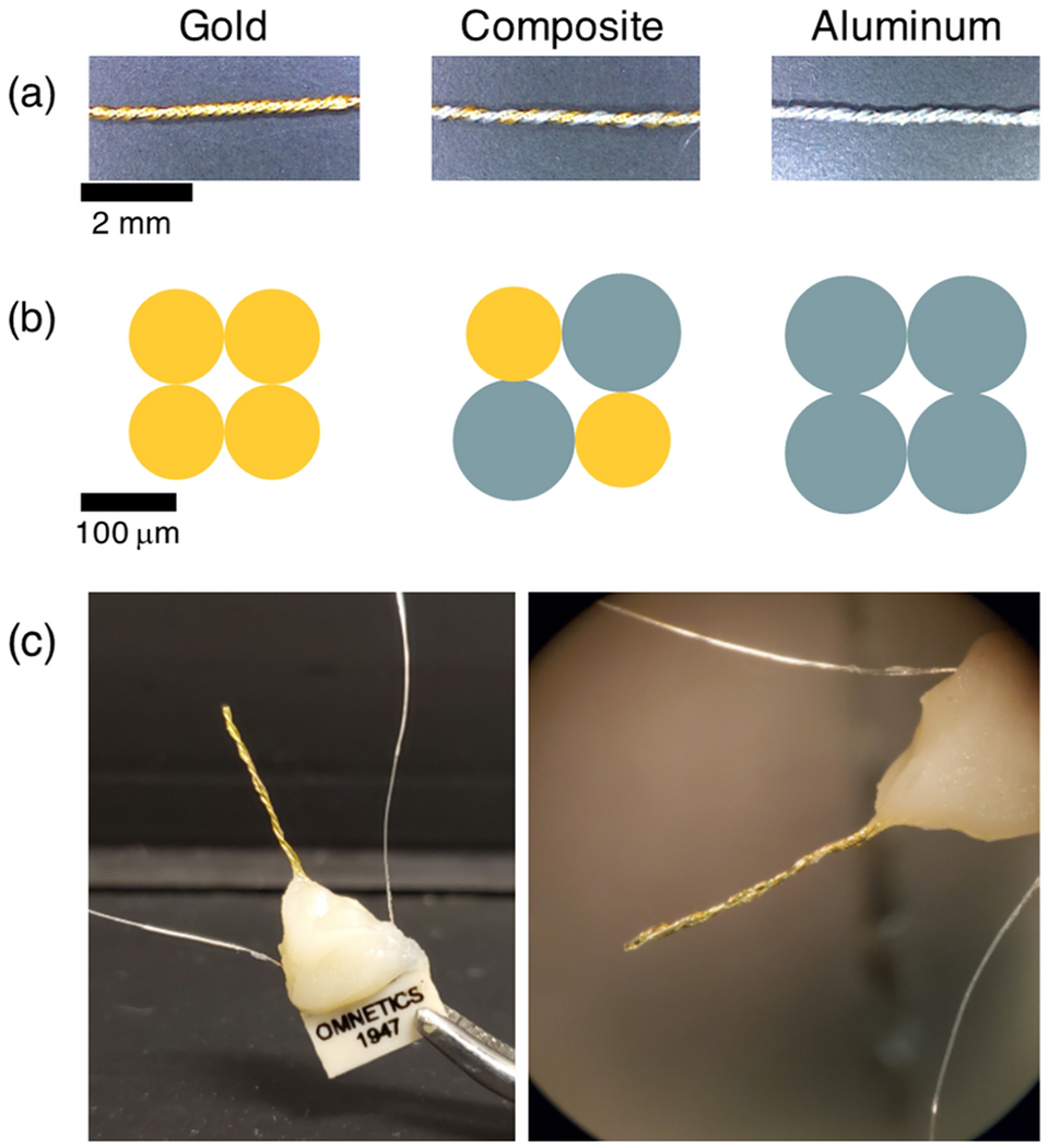
Twisted wire samples for proof-of-concept testing. (a) Side view of gold, gold-aluminum composite, and aluminum twisted wires. (b) Cross section schematic of the samples. Gold wires were 100 μm diameter; aluminum wires 125 μm diameter. (c) Neural electrode formed by twisting insulated 100 μm diameter gold and aluminum wires. Wires were soldered to a nonferrous Omnetics connector. Uninsulated silver wires served as reference and ground. Dental cement was used for mechanical support and to protect soldered connections.
4. In vivo Preparation and Imaging
A gold and a gold-aluminum twisted wire sample were implanted into the brain of a Sprague-Dawley rat for in vivo MRI at 16.4T. The rat was anesthetized using 5% isoflurane and an induction chamber and was subsequently orally intubated and positioned into a stereotaxic system and head fixed using bite and ear bars. The isoflurane concentration was reduced to 2% for the duration of the surgery and experiment. Body temperature was monitored and maintained at 37°C using a heated water bath and a ventilator was used to control breathing. Physiological parameters were monitored and adjustments to the water bath temperature and ventilator were made to maintain them in the normal range. Craniotomies were made over both hemispheres approximately 3 mm lateral from the midline and 0 mm posterior from the bregma. The gold and gold-aluminum twisted wire samples were inserted approximately 5 mm deep in the right and left hemispheres respectively and fixed in place with dental cement. The rat was then transported from surgery into an MRI-compatible holder and positioned in the 16.4T animal research scanner. All animal procedures were approved by the Institutional Animal Care and Use Committee (IACUC) at the University of Minnesota.
B0 shimming was performed using a 3D shim sequence and GEMS imaging was collected with a matrix size of 256 by 256, field of view of 24 by 24 mm (in-plane resolution 94 μm), and slice thickness 0.5 mm. GEMS was performed in multiple orientations, and for the transverse orientation we used a TE array as in the phantom imaging. B0 field maps were computed from GEMS transverse imaging using the multiple echoes. Additionally, gradient recalled echo-echo planar imaging (GRE-EPI) was performed with a matrix size of 64 by 96 and FOV 16 by 24 mm (in-plane resolution 250 μm) and slice thickness 0.5 mm, 8 slices using 4 shots with TE 6 ms and TR 2 seconds per volume.
5. Neural Electrode Preparation
Insulated gold and aluminum wires 100 μm in diameter and insulated with PTFE and polyimide respectively were obtained from California Fine Wire Company. Two gold and two aluminum wires were twisted together, and the insulation was carefully removed from one end with the aid of a microscope. The wires were soldered directly to a nonferrous Omnetics connector along with uninsulated silver wires to serve as reference and ground contacts. Biocompatible dental cement was used to provide mechanical support. A prototype 4-channel electrode is depicted in Figure 1 (c).1
Neural electrode channel impedance was measured to check the connections between the electrode contact surfaces at the wire tips and the connector pinouts. Impedance was measured at 1 kHz using the impedance function of a Cereplex M headstage from Blackrock Microsystems. The impedance was measured multiple times in a saline bath (0.9% NaCl) and in air for comparison. The multiple measurements were averaged, and the conductance was computed by taking the reciprocal of impedance values for comparison.
6. In vivo Extracellular Field Potential Recording
Extracellular local field potentials were recorded from the cortex of a Sprague-Dawley rat. Anesthesia, monitoring, and support were similar to the parameters previously described. A craniotomy was made over the somatosensory trunk region (3 mm lateral from midline, 3 mm posterior from bregma) and the twisted wire electrode was inserted to a depth of 1.5 mm. Reference and ground wires were placed between exposed tissue and the skull. Extracellular recording was performed at 30 kHz using a Cerebus Neural Signal Processor system from Blackrock Microsystems. The data were lowpass filtered at 300 Hz, downsampled to 1200 Hz, and highpass filtered at 1 Hz to visualize the local field potential. Powerline noise was removed by adaptive filtering. The isoflurane anesthesia concentration was varied between 1.2% and 2% to modulate neuronal signaling.
Results
Agarose phantom B0 mapping results indicated that the composite gold-aluminum twisted wire sample generated substantially less field distortion in comparison with twisted wire samples of gold only or aluminum only. The experimental result is shown along with an analytical-based solution in Figures 2 and 3. Both the size and the intensity of the field perturbations match closely between the experimental result (top row), and the analytical-based solutions (bottom row). Further, note the dipole flip between gold and the gold-aluminum and aluminum samples. The gold sample has magnetic susceptibility around −34 ppm, which is more diamagnetic than water which has susceptibility around −9 ppm. In contrast, both the gold-aluminum and aluminum samples are more paramagnetic than water. The gold-aluminum sample susceptibility is estimated to be −0.6 ppm (diamagnetic, but less so than water), and the aluminum sample susceptibility is 20.7 ppm. The dipole shaped distortion generated by the samples shows enhancement of the B0 field along the B0-axis for the aluminum and gold-aluminum samples, while the gold sample generates an opposition to the B0 field. The dipole orientation for the composite electrode was similar with that of aluminum electrode since the susceptibility difference between aluminum and water is larger than that between gold and water.
Figure 2.
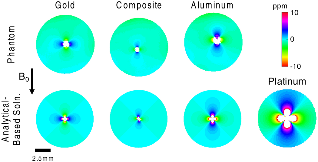
Comparison of phantom B0 mapping result at 16.4T (top row) with analytical-based solution (bottom row) for gold, gold-aluminum composite, aluminum twisted wire samples. Paramagnetic aluminum produced the largest distortions in phantom B0 mapping, followed by diamagnetic gold, and finally gold-aluminum composite samples. The analytical-based solutions match the phantom experimental results. The lower-right subplot shows the analytical-based solution for four platinum wires (100 μm diameter), commonly used in neural electrodes.
Figure 3.
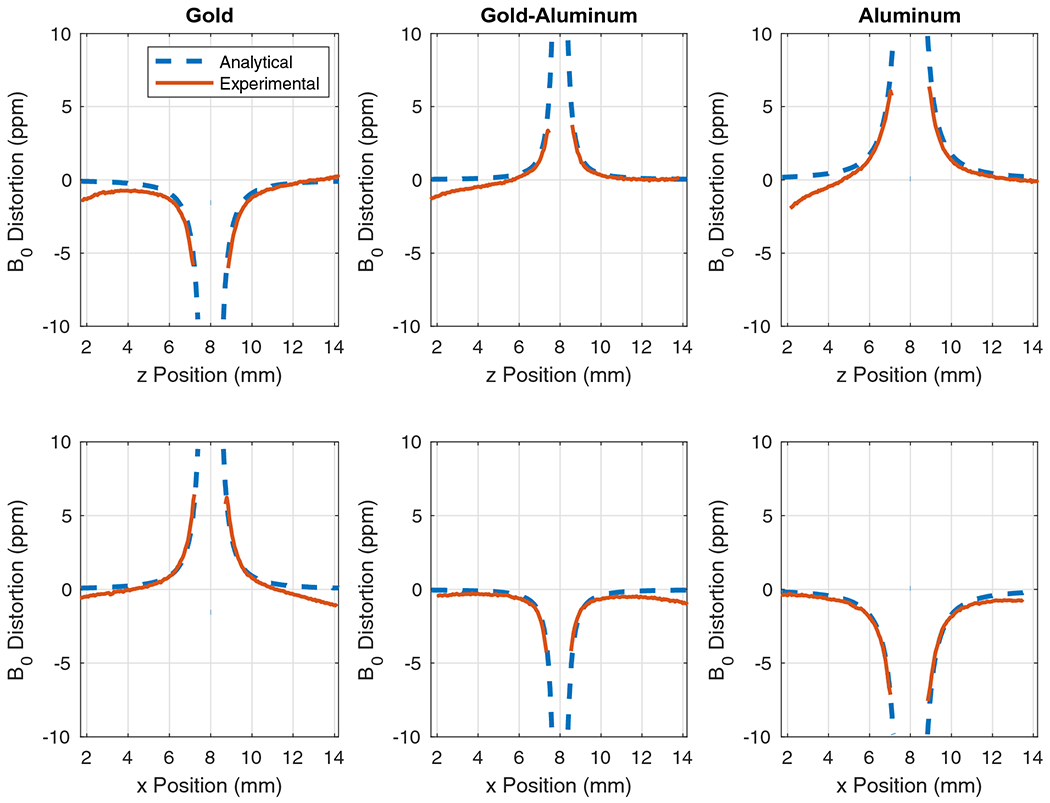
Plots comparing the analytical-based solution and experimental result for B0 field distortion along the z-direction (top row) and x-direction (bottom row) for a line passing through the center of each of the three samples. Experimental results were aligned with analytical computations, and masked where B0 distortion computation became inaccurate due to signal loss near the sample.
The results can be further quantified by examining the plots in Figure 3, which present the B0 distortions from Figure 2 for lines passing through the centers of the samples. The top row shows the distortions along the z-direction (B0 field direction), and the bottom row shows distortions along the perpendicular axis. The maximum distortion and the width of the masked regions (which were generated based on inaccuracy of B0 computation and phase mapping due to signal loss) can be examined to quantify the distortions, and are presented in Table 1. The results show that the aluminum sample generated the largest regions of signal loss and the maximum distortions observable adjacent to the signal loss regions. The gold-only sample was better than the aluminum-only sample, but the best results were obtained from the gold-aluminum sample.
Table 1.
Maximum distortions and mask widths along z- and x-directions
| Max. Distortion in z (ppm) | Mask width in z (mm) | Max. Distortion in x (ppm) | Mask width in x (mm) | |
|---|---|---|---|---|
| Gold | −6.0 | 1.7 | 6.4 | 1.6 |
| Gold-aluminum | 3.7 | 1.2 | −4.3 | 1.2 |
| Aluminum | 6.4 | 1.9 | −7.6 | 1.8 |
Results from in vivo imaging of a gold-aluminum twisted wire sample and gold twisted wire sample in the rat brain were consistent with results of the phantom experiment. GEMS imaging of the rat in the coronal orientation is presented in Figure 4. The gold and gold-aluminum wire samples are both apparent in multiple contiguous slices (0.5 mm thick) and are marked by arrows as G and C respectively for clarity. GEMS imaging suffers from the magnetic susceptibility artifact, caused by shortening of the transverse magnetization decay time, T2*, due to signal dephasing. The magnetic susceptibility artifact can be observed around both the gold and gold-aluminum wire samples in Figure 4, with the artifact around the gold sample more severe due to a larger difference in magnetic susceptibility relative to the brain tissue in comparison to the gold-aluminum composite sample. Imaging around the gold sample generates a large region of signal void of up to 1.41 mm wide, whereas imaging around the gold-aluminum sample enables visualization of the wire twists (slices 4 and 5) and smaller signal voids up to 0.85 mm across.
Figure 4.
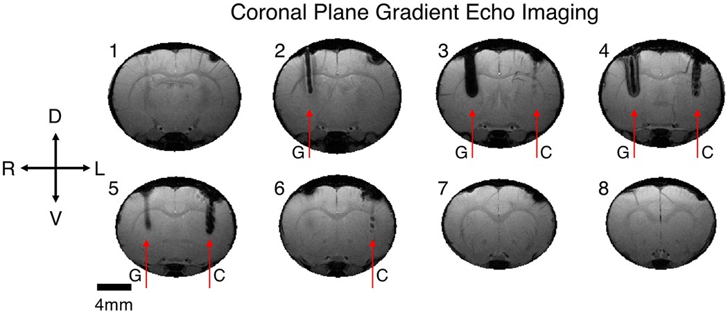
Coronal gradient echo multiple slice (GEMS) imaging of a rat implanted with a twisted gold wire sample (G) in the right hemisphere, and a twisted gold-aluminum composite wire sample (C) in the left hemisphere. The gold-aluminum wire sample created a smaller image artifact and was visible in fewer slices in comparison to the gold wire sample. Slices increase from 1 to 8 from caudal to rostral. Slice thickness 500 μm, in plane resolution 94 μm, matrix size 256 by 256.
GEMS was also performed in the transverse plane of the implanted rat. The GEMS magnitude image is presented in the top panel of Figure 5. Again, both the gold (right hemisphere) and gold-aluminum composite (left hemisphere) samples show a magnetic susceptibility artifact, with the artifact caused by the gold sample more severe and producing a distorted, non-circular shape. In the AP direction (z-direction), the lengths of artifacts caused by both the gold and the gold-aluminum samples were both 1.0 mm, but in the RL direction (x-direction), the artifact generated by the gold sample was 1.1 mm wide, compared to 0.75 mm wide for the gold-aluminum sample. Additionally, multiple echoes were acquired to enable generation of a B0 map using (2). The B0 map is presented in the lower panel of Figure 5, with labels of the twisted wire sample positions. Contours were included to improve visualization. The in vivo result also shows larger and more intense B0 distortions for the gold twisted wire sample in comparison with the novel gold-aluminum composite sample.
Figure 5.
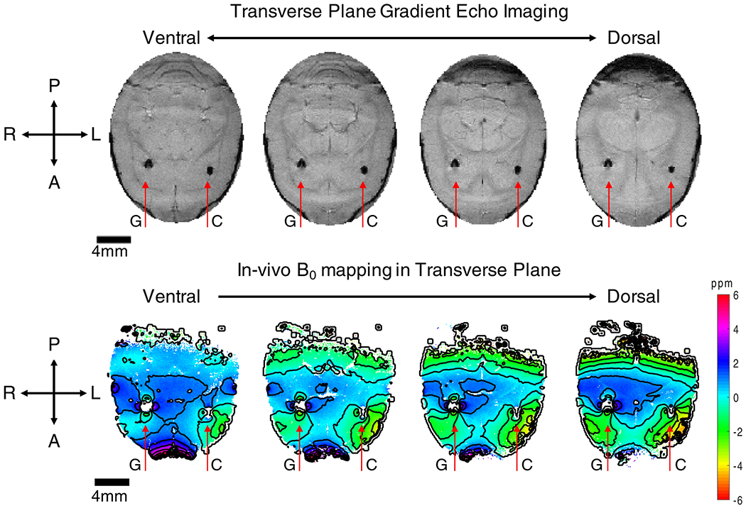
Transverse gradient echo multiple slice (GEMS) imaging (top row) and B0 mapping (bottom row) of a rat implanted with gold (G) and gold-aluminum composite (C) twisted wire samples. The gold wire sample produced larger artifacts and field distortion than the gold-aluminum sample. Slice thickness 500 μm, in plane resolution 94 μm, matrix size 256 by 256.
Finally, GRE-EPI was performed in the coronal plane of the rat implanted with the gold and gold-aluminum wire samples. GRE-EPI is particularly susceptible to artifacts, in part due to long echo times that allow for a greater degree of signal dephasing. Using multiple shots to shorten TE can help combat susceptibility-induced artifacts. Even using 4 shots to shorten TE to 6 ms, substantial regions of signal loss are observed around the gold twisted wire sample, up to 1.75 mm wide in Figure 6. Signal loss around the gold-aluminum sample is less severe but still apparent (up to 1.25 mm across).
Figure 6.
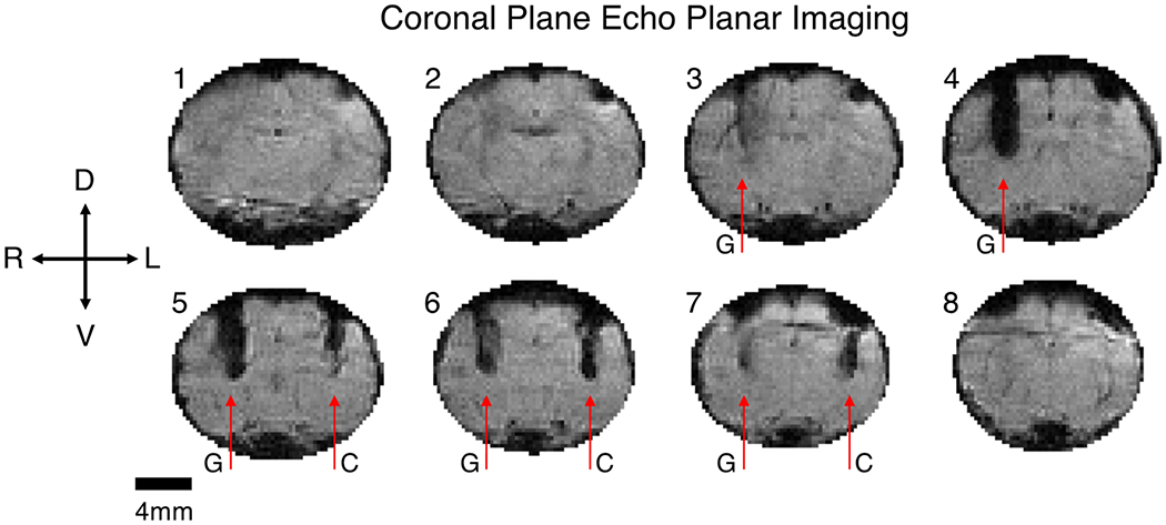
Coronal echo planar imaging (EPI) of a rat implanted with gold (G) and gold-aluminum composite (C) twisted wire samples. The gold sample produced larger regions of signal loss in comparison with the gold-aluminum sample. Imaging parameters: 64 by 96 matrix, 8 slices, in-plane resolution 250 μm, slice thickness 500 μm, four shots, TE 6 ms, TR 2 seconds per volume.
After testing the twisted wire samples in agarose phantom and in vivo in the rat brain, a functional neural electrode comprising 2 gold and 2 aluminum wires twisted together was fabricated and tested in a saline bath and in vivo. The 1 kHz impedance was measured with the electrode both outside of and inside the saline bath, with the expectation of a substantial decrease in impedance upon inserting the electrode into the saline bath. The results are plotted in Figure 7 as conductance (inverse of impedance) for each channel in air and in saline. The conductance substantially increased from less than 0.5 MΩ−1 (greater than 2 MΩ impedance) to over 2 MΩ−1 (less than 0.5 MΩ impedance) for each channel. The gold wire channels (1 and 4) exhibited higher conductance than the aluminum channels (2 and 3).
Figure 7.
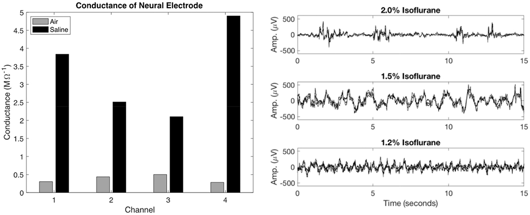
Conductance of neural electrode channels in air and in saline bath at 1 kHz (left). The increase in conductance in saline confirms electrode connection and function prior to in vivo testing. Channels 1 and 4 correspond to gold wires, channels 2 and 3 correspond to aluminum wires. Local field potential (LFP) recorded with the gold-aluminum twisted neural electrode in the rat cortex under varying levels of isoflurane anesthesia (2.0%, 1.5%, and 1.2%, right). The recordings from each of the 4 electrode contacts are superimposed in each subplot. As anesthesia level decreased from 2.0% to 1.2%, cortical LFP transitioned from burst suppression (top panel) to sustained oscillation (bottom panel).
In vivo local field potential recordings were made in the rat brain using the neural electrode prototype. The signals from the 4 electrode channels are plotted together in the 3 panels on the right hand side of Figure 7. Within each panel, the 4 electrode traces are highly correlated as expected when measuring the local field potential at several closely located points in the brain tissue. Additionally, changes in the brain state caused by varying the anesthesia level were clearly observed by the electrodes. At 2.0% isoflurane, burst suppression activity was evident. Lowering the anesthesia concentration to 1.5% isoflurane and 1.2% isoflurane revealed a transition from burst suppression to sustained oscillations.
Discussion
The novel gold-aluminum twisted wire sample outperformed gold-only and aluminum-only samples, as seen through several experiments performed in UHF MRI. B0-field maps were generated from agarose phantom imaging at 16.4T using a GEMS sequence with multiple echoes. The maximum distortion to the B0 field generated by the gold-aluminum sample was substantially less than the distortions caused by the gold-only and aluminum-only samples, as seen in Figure 2. The superior performance of the gold-aluminum sample is attributed to its effective volume magnetic susceptibility, which we estimated to be approximately −0.6 ppm, in comparison to values of −34 ppm for gold, and 20.7 ppm for aluminum respectively. In comparison with the magnetic susceptibility of water (−9 ppm), the gold-aluminum sample provides the closest match and therefore the smallest distortion to the B0-field. The demonstrated improvement of the gold-aluminum electrode in comparison to pure gold and pure aluminum samples also indicates an improvement over platinum-based electrodes. The magnetic susceptibility of platinum is around 270 to 280 ppm, and therefore is approximately 10-fold worse than pure gold or pure aluminum from a magnetic compatibility standpoint.
An analytical-based computation involving the superposition of the B0-field distortion from individual cylinders was used to estimate the total B0-field distortion generated by multi-wire samples. The computational results agreed well with the experimental result, showing less distortion around the gold-aluminum wire sample in comparison to the others, and increasing our confidence in the accuracy and validity of the experimental result and prompting the in vivo experimental studies in the rat brain.
The in vivo imaging study consisted of GEMS and EPI imaging of gold-aluminum composite and gold-only twisted wire samples acutely implanted in the rat brain. The GEMS images, which are susceptible to T2* dephasing artifacts caused around B0-field distortions, showed clearly the enlargement of the gold-only sample in comparison to the gold-aluminum sample. This result is consistent with the B0 mapping in agarose phantoms. The larger B0-field distortion results in a larger region of signal loss in GEMS imaging around the gold-only sample, which is caused by increased dephasing of the transverse magnetization signal within the voxels nearby the implant. Furthermore, B0-maps generated from the in vivo transverse GEMS imaging using multiple echoes showed a larger dipole B0 field around the gold-only implant than around the gold-aluminum implant. The results from EPI, which is even more prone to susceptibility-induced artifacts, showed a similar pattern as the higher spatial resolution GEMS images. Taken together, all these results show the effectiveness of the gold-aluminum design in reducing field distortions, and the importance of the magnetic susceptibility property of microwire electrodes for use in high field and ultrahigh field MRI.
The success of the preliminary studies using twisted wire samples led to further work to prepare a functional microwire multi-electrode prototype that could be used for recording or stimulation. For the prototype electrode, we acquired insulated gold and aluminum wire samples, each 100 microns in diameter. With an equal contribution from the matched volumes of gold and aluminum, the estimated effective magnetic susceptibility of the prototype electrode is −6.7 ppm, only 2.3 ppm from the value of water. To provide some perspective on the variation of susceptibility values in vivo, the magnetic susceptibility of human tissue has been estimated to be with approximately 2 ppm of water 24 A value of −6.7 ppm is therefore a substantial improvement even from the twisted wire sample used in initial testing in this work, which had a value around −0.6 ppm. In comparison with more conventional paramagnetic electrode materials such as platinum (270-280 ppm), iridium oxide (146 ppm), and even tungsten (74 ppm), our gold-aluminum electrode offers a dramatic improvement. Even the gold-only and aluminum-only samples, which were shown to be substantially worse than a gold-aluminum sample, are much better from a magnetic susceptibility viewpoint for high field and UHF MRI.
The microwire multi-electrode prototype was tested for its ability to record local field potentials from the rat cortex, as shown in Figure 7. Interestingly, impedance testing revealed lower conductance of the aluminum wires in comparison to the gold wires. The lower conductance could be caused by inferior bonding between the aluminum wires and the connector, or by the formation of native oxides on the aluminum tissue-contact points. The lower conductance resulted in more 60-Hz AC noise coupling into the aluminum wire channels, which was addressed with 60-Hz notch filtering. We propose two improvements to the design that should resolve the decreased conductance of the aluminum channels: 1) electroplating gold on the outside surface where the microwires contact the tissue prior to native oxide formation and 2) including a small MR-compatible PCB for improved contact fidelity between the microwires and the connector. Neither of these changes are expected to substantially alter the magnetic properties of the device. Further, gold electroplating will improve the long-term performance of the device as gold is a noble metal with improved stability over time. Finally, electroplating will result in a roughened contact surface which increases the electrochemical surface area between the electrode and tissue, further improving conductance which will benefit both stimulation and recording.
The anticipated B0 field distortions around the prototype electrode with equal diameters of gold and aluminum wires are simulated and depicted in the top row of Figure 8 (c), along with comparisons to the ideal ratio of gold and aluminum (b), and the samples studied at 16.4T in this work (a), (d), and (e). Additionally, the transverse signal decay contribution due to the presence of the wire samples is shown in the bottom row of Figure 8 assuming 94 μm square voxels with 15 ms echo time, 25 ms T2 for the agarose phantom, and neglecting the contribution of encoding gradients to within-voxel field inhomogeneity. This figure illustrates the further improvement of using balanced diameters of 100 μm for both the gold and aluminum wires in the composite electrode, and that this equal ratio performs almost as well as the ideal gold/aluminum ratio depicted in Figure 8 (b).
Figure 8.
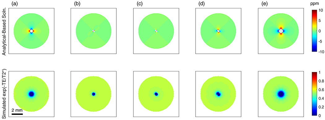
Field distortion computations around wire samples (top row) and estimated transverse signal decay caused by the presence of the wires (bottom row) neglecting encoding gradient effects. (a) 4 gold wires of 100 μm diameter, (b) 2 gold wires 104 μm diameter and 2 aluminum wires 96 μm diameter, (c) 2 gold and 2 aluminum wires 100 μm diameter, (d) 2 gold wires 100 μm diameter and 2 aluminum wires 125 μm diameter, (e) 4 aluminum wires 125 μm diameter.
Both gold and aluminum have been classified as non-reactive with cerebral tissues, the same classification given to platinum and tungsten which are frequently used as neural electrode materials 28. This provides a distinct advantage over the use of copper, which while having a magnetic susceptibility value very close to tissue, is toxic and requires special consideration on how to effectively protect surrounding neural tissue from damage. The authors of 30 have shown that graphene encapsulation is effective, but growth of high quality graphene on copper is technically difficult in comparison with twisting non-reactive gold and aluminum microwires. Electroplating gold on the microwires to improve long-term stability and increase surface roughness is also easy in comparison to growing high quality graphene encapsulation layers.
The new gold-aluminum composite microwire electrode design presented in this work provides a substantial advantage over traditional microwire electrode materials such as tungsten and platinum in UHF MRI. The effective magnetic susceptibility value of the gold-aluminum sample is within a few ppm of the estimated values for human tissues and is fabricated from materials that are non-reactive with cerebral cortex tissue. We showed reduced MRI image artifacts even at the UHF of 16.4T. Because the magnetic susceptibility properties of paramagnetic and diamagnetic materials should not substantially change in the range of magnetic field strengths for MRI, our results translate to lower field strengths such as 1.5T, 3T, 4T, and 7T as well. Additionally, the use of non-reactive materials provides a path for future translation to human clinical studies. Finally, we successfully demonstrated the ability to record field potentials from the rat cortex using a prototype electrode. Future studies will aim to elucidate the utility and fidelity of our novel gold-aluminum microwire electrode for brain stimulation and simultaneous study at UHF of 16.4T.
ACKNOWLEDGEMENTS
This work was supported in part by NIH grant R01 MH111413, P41 EB027061, P30 NS076408, S10 RR025031, and by the University of Minnesota’s MnDRIVE (Minnesota’s Discovery, Research and Innovation Economy) initiative.
Footnotes
Publisher's Disclaimer: This Author Accepted Manuscript is a PDF file of an unedited peer-reviewed manuscript that has been accepted for publication but has not been copyedited or corrected. The official version of record that is published in the journal is kept up to date and so may therefore differ from this version.
CONFLICT OF INTEREST STATEMENT
A portion of the work reported in this paper has been protected through a patent filing. The pending patent will belong to the University of Minnesota which has a standard royalty sharing agreement with university employees, in case any royalties are earned from the licensing of said patent.
References
- 1.Agnesi F, Johnson MD, and Vitek JL. Deep brain stimulation: how does it work? In: Handbook of Clinical Neurology Vol. 116. 2013, pp. 39–54.doi: 10.1016/B978-0-444-53497-2.00004-8 [DOI] [PubMed] [Google Scholar]
- 2.Bhagwandien R, Moerland MA, Bakker CJG, Beersma R, and Lagendijk JJW. Numerical Analysis of the Magnetic Field for Arbitrary Magnetic Susceptibility Distributions in 3D. Magn. Resort. Imaging 12:101–107, 1994. [DOI] [PubMed] [Google Scholar]
- 3.Callister WD Jr., and Rethwisch DG. Fundamentals of Material Science and Engineering: An Integrated Approach. John Wiley & Sons, 2012. [Google Scholar]
- 4.Chiken S, and Nambu A. Mechanism of deep brain stimulation: inhibition, excitation, or disruption? Neuroscientist 22:313–322, 2016. [DOI] [PMC free article] [PubMed] [Google Scholar]
- 5.Chu K-C, Xu Y, Balschi JA, and Springer CS JR. Bulk magnetic susceptibility shifts in nmr studies of compartmentalized samples: use of paramagnetic reagents. Magn. Reson. Med. 13:239–262, 1990. [DOI] [PubMed] [Google Scholar]
- 6.Cogan SF Neural stimulation and recording electrodes. Annu. Rev. Biomed. Eng. 10:275–309, 2008. [DOI] [PubMed] [Google Scholar]
- 7.Cruttenden CE, Zhu X-H, Chen W, and Rajamani R. Computation of Magnetic Field Distortions and Impact on T2* -weighted MRI, with Applications to Magnetic Susceptibility Parameter Estimation. Biomed. Rhys. Eng. Express 4:045029, 2018. [DOI] [PMC free article] [PubMed] [Google Scholar]
- 8.Hariz M, Blomstedt P, and Zrinzo L. Future of brain stimulation: new targets, new indications, new technology. Mov. Disord. 28:1784–1792, 2013. [DOI] [PubMed] [Google Scholar]
- 9.Hornak JP The Basics of MRI. Henietta, NY: Interactive Learning Software, .at <https://www.cis.rit.edu/htbooks/mri/> [Google Scholar]
- 10.Jenkinson M Fast, automated, N-dimensional phase-unwrapping algorithm. Magn. Reson. Med. 49:193–197, 2003. [DOI] [PubMed] [Google Scholar]
- 11.Jenkinson M, Beckmann CF, Behrens TEJ, Woolrich MW, and Smith SM. FSL. Neuroimage 62:782–790, 2012. [DOI] [PubMed] [Google Scholar]
- 12.Jezzard P, and Balaban RS. Correction for geometric distortion in echo planar images from B0 field variations. Magn. Reson. Med. 34:65–73, 1995. [DOI] [PubMed] [Google Scholar]
- 13.Johnson MD, Miocinovic S, McIntyre CC, and Vitek JL. Mechanisms and targets of deep brain stimulation in movement disorders. Neurotherapeutics 5:294–308, 2008. [DOI] [PMC free article] [PubMed] [Google Scholar]
- 14.Lai H-Y, Younce JR, Albaugh DL, Kao Y-CJ, and Shih Y-YI. Functional MRI reveals frequency-dependent responses during deep brain stimulation at the subthalamic nucleus or internal globus pallidus. Neuroimage 84:11–18, 2014. [DOI] [PubMed] [Google Scholar]
- 15.Lee JY, Kim JW, Lee J-Y, Lim YH, Kim C, Kim DG, Jeon BS, and Paek SH. Is MRI a reliable tool to locate the electrode after deep brain stimulation surgery? Comparison study of CT and MRI for the localization of electrodes after DBS. Acta Neurochir. (Wien). 152:2029–2036, 2010. [DOI] [PubMed] [Google Scholar]
- 16.Lide DR Magnetic susceptibility of the elements and inorganic compounds. In: Handbook of Chemistry and Physics. CRC Press, 2005, pp. 130–135. [Google Scholar]
- 17.McIntyre CC, Savasta M, Walter BL, and Vitek JL. How Does Deep Brain Stimulation Work? Present Understanding and Future Questions. J. Clin. Neurophysiol. 21:40–50, 2004. [DOI] [PubMed] [Google Scholar]
- 18.Merrill DR The Electrode - Materials and Configurations. In: Essential Neuromodulation, edited by Arle JE, and Shils JL. Academic Press, 2011, pp. 109–146. [Google Scholar]
- 19.Müller-Bierl B, Graf H, Steidle G, and Schick F. Compensation of magnetic field distortions from paramagnetic instruments by added diamagnetic material: measurements and numerical simulations. Med. Phys. 32:76–84, 2005. [DOI] [PubMed] [Google Scholar]
- 20.Ogawa S, and Lee T-M. Magnetic resonance imaging of blood vessels at high fields: in vivo and in vitro measurements and image simulation. Magn. Reson. Med. 16:9–18, 1990. [DOI] [PubMed] [Google Scholar]
- 21.Ogawa S, Lee T-M, Nayak AS, and Glynn P. Oxygenation-sensitive contrast in magnetic resonance image of rodent brain at high magnetic fields. Magn. Reson. Med. 14:68–78, 1990. [DOI] [PubMed] [Google Scholar]
- 22.Ogawa S, Tank DW, Menon R, Ellermann JM, Kim SG, Merkle H, and Ugurbil K. Intrinsic signal changes accompanying sensory stimulation: functional brain mapping with magnetic resonance imaging. Proc. Natl. Acad. Sci. 89:5951–5955, 1992. [DOI] [PMC free article] [PubMed] [Google Scholar]
- 23.Pollo C, Villemure J-G, Vingerhoets F, Ghika J, Maeder P, and Meuli R. Magnetic resonance artifact induced by the electrode Activa 3389: An in vitro and in vivo study. Acta Neurochir. (Wien). 146:161–164, 2004. [DOI] [PubMed] [Google Scholar]
- 24.Schenck JF The role of magnetic susceptibility in magnetic resonance imaging: MRI magnetic compatibility of the first and second kinds. Med. Phys. 23:815–850, 1996. [DOI] [PubMed] [Google Scholar]
- 25.Shih Y-YI, Yash TV, Rogers B, and Duong TQ. fMRI of Deep Brain Stimulation at the Rat Ventral Posteromedial Thalamus. Brain Stimul. 7:190–193, 2014. [DOI] [PMC free article] [PubMed] [Google Scholar]
- 26.Sironi VA Origin and evolution of deep brain stimulation. Front. Integr. Neurosci. 5:42, 2011. [DOI] [PMC free article] [PubMed] [Google Scholar]
- 27.Smith SM, Jenkinson M, Woolrich MW, Beckmann CF, Behrens TEJ, Johansen-Berg H, Bannister PR, De Luca M, Drobnjak I, Flitney DE, Niazy RK, Saunders J, Vickers J, Zhang Y, De Stefano N, Brady JM, and Matthews PM. Advances in functional and structural MR image analysis and implementation as FSL. Neuroimage 23:S208–S219, 2004. [DOI] [PubMed] [Google Scholar]
- 28.Stensaas SS, and Stensaas LJ. Histopathological evaluation of materials implanted in the cerebral cortex. Acta Neuropathol. 41:145–155, 1978. [DOI] [PubMed] [Google Scholar]
- 29.Uğurbil K, Adriany G, Andersen P, Chen W, Garwood M, Gruetter R, Henry PG, Kim SG, Lieu H, Tkac I, Vaughan T, Van De Moortele PF, Yacoub E, and Zhu XH. Ultrahigh field magnetic resonance imaging and spectroscopy. Magn. Resort. Imaging 21:1263–1281, 2003. [DOI] [PubMed] [Google Scholar]
- 30.Zhao S, Liu X, Xu Z, Ren H, Deng B, Tang M, Lu L, Fu X, Peng H, Liu Z, and Duan X. Graphene Encapsulated Copper Microwires as Highly MRI Compatible Neural Electrodes. Nano Lett. 16:7731–7738, 2016. [DOI] [PubMed] [Google Scholar]


