

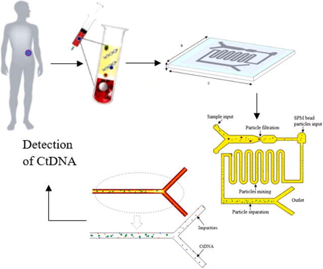
Graphical abstract
Keywords: Circulating tumor DNA (ctDNA) detection, Cancer biomarker, Liquid biopsy Magnetic manipulation, COMSOL Multiphysics Simulation study
Highlights
-
•
CtDNA extraction from blood samples by superparamagnetic (SPM) bead particles in a microfluidic platform for early cancer detection was proposed.
-
•
Computer experiments were conducted in COMSOL Multiphysics 5.3a software by using blood samples from stage I and II cancer patients to extract ctDNA.
-
•
An average of 5.7 ng of ctDNA was separated for every 10 µL of whole plasma input.
-
•
The simulation also showed that the device has ctDNA detection sensitivity and specificity of 65.57% and 95.38%, respectively for samples from stage I and II cancer patients.
-
•
The microchannel design with filtration method and separation by SPM bead particles has proved the effective ctDNA extraction from samples of stage I and II cancer patients.
Abstract
Introduction
Conventional biopsy, based on extraction from a tumor of a solid tissue specimen requiring needles, endoscopic devices, excision or surgery, is at risk of infection, internal bleeding or prolonged recovery. A non-invasive liquid biopsy is one of the greatest axiomatic consequences of the identification of circulating tumor DNA (ctDNA) as a replaceable surgical tumor bioQpsy technique. Most of the literature studies thus far presented ctDNA detection at almost final stage III or IV of cancer, where the treatment option or cancer management is nearly impossible for diagnosis.
Objective
Hence, this paper aims to present a simulation study of extraction and separation of ctDNA from the blood plasma of cancer patients of stage I and II by superparamagnetic (SPM) bead particles in a microfluidic platform for early and effective cancer detection.
Method
The extraction of ctDNA is based on microfiltration of particle size to filter some impurities and thrombocytes plasma, while the separation of ctDNA is based on magnetic manipulation to high yield that can be used for the upstream process.
Result
Based on the simulation results, an average of 5.7 ng of ctDNA was separated efficiently for every 10 µL blood plasma input and this can be used for early analysis of cancer management. The particle tracing module from COMSOL Multiphysics traced ctDNA with 65.57% of sensitivity and 95.38% of specificity.
Conclusion
The findings demonstrate the ease of use and versatility of a microfluidics platform and SPM bead particles in clinical research related to the preparation of biological samples. As a sample preparation stage for early analysis and cancer diagnosis, the extraction and separation of ctDNA is most important, so precision medicine can be administered.
Introduction
Cancer is known as the primary cause of world level mortality and morbidity. Over the past two decades, major advances in molecular biology have allowed several improved therapies for cancer treatment, however, these have caused numerous drawbacks for instance, and deficiency of drugs against most genomic aberrations and surgical examination of tumor tissue may lead to infections [1]. These issues have received considerable critical attention thus, recent advancement revealed that analysis of circulating tumor DNA (ctDNA) as cancer biomarker is amenable for a noninvasive liquid biopsy which gives quick access to study the tumor sample [2], [3].
CtDNA is a single or double-stranded DNA that is shed from primary cancerous cells and tumor cells into the circulatory or lymphatic system. CtDNA as tumor-derived fragmented DNA typically found in plasma or serum of the patient’s blood, able to provide information and define characteristics of the original tumor [4]. This has illuminated fruitful information as a promising cancer biomarker in the liquid biopsy to detect and diagnose cancer at an early stage. CtDNA detection as well as an early invasive cancer biomarker can reveal mint of biological information about the tumor and the realization of the concept of precision medicine is highly possible according to the patient’s need [4], [5]. The number of ctDNA differs depending on the stage and location of the primary tumor [6], [7]. Various studies have assessed the efficacy of ctDNA as a cancer biomarker through several methods. For example, droplet digital polymerase chain reaction (ddPCR) is known for the most accurate tool to detect known mutation; beads, emulsion, amplification and magnetics (BEAMing) is inexpensive and fairly accurate but it screens known mutation only; tagged-amplicon deep sequencing (TAm-Seq) has the ability of sequence millions of DNA molecules; cancer personalized profiling by deep sequencing (CAPP-Seq) has ctDNA detection with the ability of 100% in stage IV cancer; whole-genome sequencing (WGS) shows great potential in clinical decision-making and rare mutations oncogenes [8], [9], [10].
A large and growing body of literature has investigated the feasibility of ctDNA in the early detection of metastasis throughout tumor progression. It has conclusively been shown that ctDNA detection is comparative to cancer stages. The detection rate is 90–100% for II-IV compared to stage I which is 50% for a specific cancer type [9], [11]. Data from several sources also have stated that it is easier to separate and detect ctDNA than circulating tumor cells (CTCs) as ctDNA is more stable and higher in proportion in the bloodstream with high sensitivity [12], [13], [14], [15], [16]. Their concentration is directly proportional to the tumor cascade [17], [18]. In a recent study by Coombes et al. (2019), plasma ctDNA was detected with a sensitivity of 89% and specificity of 100% in cancer patients of stage 0.5–24.0 months. This detection up to the cancer stage of 2 years provides a possible window for therapeutic intervention [19]. Most of the studies presented thus far convey insights about ctDNA detection at almost final stage III or IV of cancer, where the number of escalating ctDNA can be observed quite clearly in the circulatory system. Although ctDNA analysis is noninvasive biopsy detection, these methods are limited to detecting cancer at a critical stage. Such approaches, however, have failed to address the capability of ctDNA analysis in the early stage of cancer progression. This is mainly due to the inadequate amount of ctDNA that is present in the early stage of cancer. Despite the tremendous potential of ctDNA in cancer research, there remains a paucity of a quantitative study on ctDNA detection and analysis due to the complexity of ctDNA isolation as that is present in low concentrations in blood plasma. Thus, we anticipated the development of extraction and separation of ctDNA from blood plasma by superparamagnetic (SPM) bead particles in a microfluidic platform for early and effective cancer detection. Besides detection, ctDNA has great potential in cancer management particularly from detection, diagnosis, precision treatment selection and monitoring or follow-up disease condition including non-hematological as well as progression. In a clinical study, SPM bead particles are mainly used for magnetic DNA purification as a replaceable technique for centrifuge and vortex dependent sample preparation system. They can be used to isolate, extract, purify and separate DNA from a biological raw sample [20]. As a pilot study, computer experiments were conducted in COMSOL Multiphysics 5.3a software by using a blood sample from stage I and II cancer patients to extract ctDNA for prompt cancer detection. COMSOL multiphysics® simulation software was used for a preliminary study to prove the concept of this study work. It is a cross-platform finite element analysis (FEA) and solver based on an advanced numerical computerized method for simulating scientific and engineering problems. The software provides an interactive environment for modeling and enables the reaction study of designs and devices towards real-world effects. Accordingly, an accurate device can be fabricated without misleading findings [21,22].
Materials and methods
The computer experiments for this work consisted of three simulation studies, which began with modeling of a microfluidic device, a study of ferromagnetic material for magnetic manipulation and lastly coupling of ctDNA extraction by SPM bead particles with manipulation of the permanent magnet in a microfluidic platform. The detailed descriptions of every simulation study have presented in the following subsections.
Modeling of the geometry of the microfluidic device
As shown in the perspective view of the device, Fig. 1, the substrate was a rectangle of 75 mm length, 50 mm width and 1 mm thick made up of polycarbonate material which is also known as a thermoplastic polymer. The polycarbonate material is naturally compatible with testing biological samples due to its characteristic of less hydrophobicity thus, the microchannel showed better filling behavior for laminar flow. Moreover, the microfluidic channels can be directly used for further downstream processes that required higher temperature applications such as PCR with chemicals such as diluted acids, oils and alcohol deprived of a secondary reaction.
Fig. 1.

Perspective view of a microfluidic device made up of polycarbonate substrate with a = 50 mm, b = 1 mm and c = 75 mm.
The overall microfluidic channel was designed of 55 mm in length, 40 mm in width and 150 µm thick on the substrate. It was composed of three parts: 1. the main rectangle channel of two different inlet points with multi-width; 2. curved microchannel for micro-mixing; 3. rectangle channel with an outlet for magnetic manipulation. The detailed design of the microchannel is described in Fig. 2. The two inlets at the most left of the channel were used for input of blood plasma and buffer solution which acts as lysis solution and also will promote the binding of ctDNA into SPM bead particles in later part, while another inlet point was mainly for the input of SPM bead particle (Dynabeads Silane DNA kit from Thermo Fisher Scientific). The different widths in the main channel as shown in Fig. 2, (a = 5 µm and b = 2 µm) was used to separate ctDNA from other impurities and platelets of a plasma sample. The theory here is based on microfiltration and manipulation of particle size to filter some impurities and thrombocytes plasma. The typical size of ctDNA is 2.6 nm wide with 100 bp long and thrombocytes are biconvex discoid structured with 2 µm to 3 µm in diameter whereas, the SPM bead is 1 µm sphere particle. Hence, ctDNA can be separated from thrombocytes before entering to next part of the microchannel. Another inlet at another end of the microchannel was designed with a width of 1.5 µm, especially for SPM bead particle input. At this point, the ctDNA and SPM bead particles will be moved to the second part of the curved microchannel which was designed for the effective mixing of particles. The laminar flow in the microchannel normally has limited mixing and diffusion behaviors. Hence, the circulating flow in a curved microchannel with controlled droplet motion with a low capillary number when releasing particles will enhance the mixing rate with a high surface to volume ratio in the microfluidic channel. Accordingly, ctDNA able to intermingle fully with SPM bead particles and smooth fluid movement can be expected without clogging issues for effectively attached or absorbed to SPM bead particles. As the solution moved to the third part of the microfluidic channel, a permanent magnet will be used to desorb or detach ctDNA from SPM bead particles. The SPM bead particles will be separated from ctDNA by the magnetic field by the permanent magnet to hold SPM beads while ctDNA can be collected at the outlet channel.
Fig. 2.

Detail design of microfluidic channel with 3 inlets and 2 outlets. The multi-width rectangle channel of d = 5 µm, e = 2 µm and f = 1.5 µm is used for filtration ctDNA from thrombocytes and impurities of plasma input. The ‘g’ represents a curved channel for micromixing of SPM bead particles and targeted particles. The ‘h’ represents a rectangle channel that is used for separation and enhancement of targeted particles by manipulation of a permanent magnet. The entire microchannel is designed with i = 55 mm in length and j = 40 mm in width.
To put it briefly, the extraction of ctDNA will go through microfiltration for impurities separation and then magnetic separation by SPM bead particles for enhancing the yield of ctDNA in terms of quantity as well as quality. Lastly, the simulation was considered for different mesh sizes to ensure reliable and mesh-independent results. A triangular mesh with an element size of 5 µm and 3 µm are used respectively for the microchannel and the substrate. Moreover, the simulation was studied in three time-dependent study steps: step 1. microfluidic channel flow; step 2. magnetic field in a microfluidic channel with a permanent magnet; step 3. particle extraction using particle tracing module.
Modeling of ferromagnetic material as permanent magnet
Ferromagnetic material made of pure magnetic metals of magnetite, an oxide of iron was used for this study. As shown in Fig. 3a, the permanent magnet has the material that can be magnetized by an induced external magnetic field and remain magnetized when there is no external magnetic field applied. This phenomenon is also known as ferromagnetism. The magnetic block with a dimension of 60 mm length, 10 mm width and 5 mm height will be placed at magnet array at the bottom of the microfluidic device particularly to manipulate SPM bead particles to desorb or detach ctDNA from the beads (Fig. 3b).
Fig. 3.

a) Magnetic block that made up of ferromagnetic material for ctDNA separation, b) A magnetic block placed at magnetic array at the bottom of the microfluidic channel to manipulate SPM bead particle with ctDNA.
AC/DC module in COMSOL multiphysics was used to define the properties of the magnetic block by selecting steady magnetic fields with no currents interface. Magnetostatics mechanism was replicated for the magnetic block for microchannel applications where the magnetic field does not change concerning time.
Coupling of ctDNA extraction by SPM bead particles with manipulation by a permanent magnet
A permanent magnet was manipulated for attaching and detaching SPM bead particles to collect ctDNA at the outlet channel. This study related to the separation of slow-moving microparticles using a magnetic field. Thus, the simulation was accomplished by specifying computational fluid dynamics (CFD) in laminar flow, particle tracing module and magnetic field without applied current. These three studies were integrated to visualize the extraction of ctDNA. The particle tracing module was selected based on its ability to envisage and compute particle trajectory in a fluid mixing scenario under the influence of electromagnetic force. The sample mixing and separation was accomplished in isotropic continuous flow conditions. All the parameters used to define the simulation were shown in Table 1.
Table 1.
Parameters used to define the simulation of ctDNA extraction and separation by SPM bead particles in a microfluidic channel.
| Description | Value |
|---|---|
| Average thrombocytes diameter | 2.5 µm |
| Average thrombocytes density | 1.08 g/µL |
| Average ctDNA diameter | 2.6 nm |
| Average ctDNA length | 90 bp |
| Average ctDNA density | 1.7 g/cm3 |
| Particle conductivity: ctDNA SPM bead particles input |
0.20 ms/m 2 µL |
| Average SPM bead particles diameter | 1.0 µm |
| Average SPM bead particles density | 2.0 g/cm3 |
| Particle conductivity: SPM bead particles | 0.32 ms/m |
| Particle relative permittivity: SPM bead particles | 59 |
| Impurities diameter | 2.0 µm to 1.5 µm |
| Average impurities density Sample input |
1.08 g/µL 10 µL |
| Sample inflow rate | 5 µL/min |
| SPM bead particles inflow rate Buffer solution input |
5 µL/min 20 µL |
| Buffer solutions inflow rate | 10 µL/min |
| Material fluid relative permittivity | 80 |
| Material fluid dynamic viscosity | 0.001 µPa.s |
| Fluid medium conductivity | 0.055 s/m |
| Fluid density | 1000 g/m3 |
Results
Microfluidic channel design
The particles and fluid flow in the microfluidic channel were numerically simulated using Navier-Stokes equations. A detailed illustration of the velocity flow of particles of isotropic conditions in the microfluidic channel is shown in Fig. 4.
Fig. 4.

Velocity magnitude profile (µm/s) of particles in the microfluidic channel. The Newtonian fluid and particles flow regime described parabolic velocity profile as a function of the Reynolds number in the microfluidic channel.
The laminar flow of the particles at a boundary in the velocity distribution was noticed in the simulation outcome. All the particles were released in droplet motion to avoid clogging issues, especially in a narrow microchannel. As a result, a parallel parabolic velocity profile was depicted in the microfluidic channel. Furthermore, the pressure-driven particle flow of isotropic conditions in the microfluidic channel was also a replicated laminar velocity profile as shown in the electronic supplementary material.
Analysis of magnetic material and magnetic field in a microfluidic channel
The magnetic field profile produced by the block placed underneath the microchannel was tangential to the boundary on the xy-plane and perpendicular to the boundary on the xz-plane with zero magnetic scalar potential conditions. Based on the aftermath of the model study as shown in the simulation Figure that can be found in electronic supplementary material, the orientation of the magnetic fields of the individual domains tends to line up according to the magnetic field formed by the magnet bar.
Analysis of CtDNA extraction and separation by SPM bead particles in magnetic field
The detailed phases of ctDNA filtration and separation in the presence of a magnetic field were shown in electronic supplementary material and the overall representation of the ctDNA extraction was summarised in Fig. 5.
Fig. 5.

Top view of the microfluidic channel: filtration of ctDNA from thrombocytes of plasma input, mixing of ctDNA and SPM bead particles in curved microchannel and binding of ctDNA into SPM bead particles for further separation by magnetic field.
CtDNA was filtered out from impurities and thrombocytes and then separated by SPM bead particles for high yield outcomes. The particle mixing (ctDNA and SPM bead particles) with buffer solution was shown in curved microchannel and then separated by magnetic manipulation. By using particle tracing module coupling with the electromagnetic field, ctDNA was traced and separated from SPM bead particles. The behavior of ctDNA towards SPM bead particles and feature separation as shown in Fig. 6. The detailed picture of ctDNA absorption into SPM bead particles was shown in Fig. 6 as well.
Fig. 6.

a) The flow of ctDNA, SPM bead particles and impurities in absence of magnetic field, b) CtDNA moved towards SPM bead particles, c) Binding of ctDNA into SPM bead particles where they can be detached by the applied magnetic field.
The input of buffer solution promotes binding of ctDNA into SPM bead particles. Once the ctDNA was absorbed into SPM bead particles, other molecules and impurities were washed out by using a magnetic field to hold the SPM bead with ctDNA. Then, an elution buffer with low pH and low ionic strength was dispensed to desorb the ctDNA from SPM bead particles. The ctDNA was separated from SPM bead particles and collected at the outlet channel. The final separation and collection of ctDNA were shown in Fig. 7. The strong magnetic response of the beads with high stability employing chemical as well as mechanical has promoted the ctDNA separation in a magnetic field.
Fig. 7.

Separation of ctDNA from SPM bead particles through the magnetic field formed by the magnetic block.
The separation step is significant for a high and pure yield of ctDNA collection. Although most of the impurities defined to be washed out, yet some were remaining at the long channel together with DNA and SPM beads residual. As stated in previous research work [20], further ctDNA amplification process for further analysis could be successfully implemented even in the presence of SPM beads due to the chemical properties of amplification reagent as elution buffer. The low ionic strength of the amplification reagent can be used for further desorption of DNA from SPM (if required).
The potential of the magnetic block to bind SPM beads in the suspension of ctDNA and impurities in the microfluidic channel under the influence of a weak electromagnetic field of 10 mT was noticed. Based on theoretical calculation, an average of 5.7 ng of ctDNA was separated for every 10 µL of whole plasma input (Fig. 8).
Fig. 8.

a) Enumeration of outcomes collected at the outlet channel for every 10 µL of sample, b) Enumeration of CtDNA for every 10 µL of sample where x-axis represents time(s) and y-axis represents particle count (ng).
The particle tracing equation is composed of the COMSOL simulation software based on all the below-stated equations in the following part. The simulation showed that the device has a ctDNA detection sensitivity and specificity of 65.57% and 95.38%, respectively for samples introduced from stage I and II cancer patients. Although the end yield has a residual cell concentration of less than 0.5%, the microchannel design with filtration method and separation by SPM bead particles has proved the specific ctDNA extraction from a sample of stage I and II cancer patients. This also showed that early detection of cancer is possible by the proposed device.
Discussion
Analysis of microfluidic channel design
The velocity flow was derived from the conservation principles of mass, momentum and energy for fluid flow with particles and then simplified by several assumptions to mimic actual flow in a microfluidic channel in a real situation. The assumptions were made included, the fluid flow in the microfluidic channel is incompressible (density is constant over space and time), Newtonian flow in a microfluidic channel with uniform viscosity and the fluid dynamics is based on non-slip boundary condition in the channel. Hence, the velocity flow profile can be derived from the Navier-Stokes and Reynolds number equations as below:
| (1) |
| (2) |
| (3) |
where Re is a non-dimensional number that gives the ratio between inertial and viscous forces to indicate flow regime, u (m/s) is the fluid and particle velocity field, ρ (kg/m3) is fluid and particle density, v (m2/s) is the kinematic viscosity, f (m/s2) is an external acceleration field due to gravity and L (m) is the hydraulic diameter in the microchannel. Due to the small dimensions of the microchannel, the Re is usually much less than 100, thus, the flow regime is governed by laminar flow across the device (Fig. 4) where the viscous forces dominated over inertial forces. Note, the greater velocity at the center of the microchannel was due to non-slip boundary conditions which commanded the velocity of a fluid at a stationary interface will be zero. As the particles at the center are free to flow compared to particles near the walls of the microchannel which also interacting with neighboring particles, therefore simulation defined the velocity of the particles at a boundary as equivalent to the velocity of the boundary itself. In the pressure-driven flow, the fluid was assumed to be pumped through for droplet motion in a low capillary number in the device via positive displacement pumps. The pressure driven by laminar flow and non-slip boundary condition showed a parabolic velocity profile within the channel.
Analysis of magnetic material and magnetic field in a microfluidic channel
The magnetic force formed by the magnetic bar can be defined as stated by Ampere’s circuital law as Eq. (4).
| (4) |
| (5) |
where (T) is the magnetic field magnitude, (N/A2) is the permeability of free space, (A) is the magnitude of the electric current and (m) is the distance interacting magnetic materials. Additionally, in the current free region, where given is magnetic field intensity, for the static electric field the scalar magnitude potential, is defined as . This is analogous to the definition of the electric potential for static electric fields. Using the constitutive relation between the magnetic flux density and magnetic field as shown in the graphical figure as in electronic supplementary material, the numerical simulation was solved according to equations given by the simulation module as below:
| (6) |
| (7) |
| (8) |
The magnetization of the material produced in the magnetic field when I = 0 was represented in Fig. 7. The curve which also known as the B-H loop was measured by the generated magnetic flux of the defined ferromagnetic material (magnetic block) in the presence of magnetizing force. The B-H loop was created based on the saturation point, retentivity point and coercivity point of the material. The material reached a point of saturation as shown in Fig. 7 when most of the magnetic domains are aligned in magnetizing force in a positive direction. Some magnetic flux remains in the material once the magnetizing force is reduced to zero. This level of residual magnetism in the material is shown by the point of retentivity. Coercivity occurred when the magnetizing force is reversed and has flipped enough domains in zero magnetic flux within the material. As the magnetizing force is increased in a negative direction, again the material becomes magnetically saturated in the opposite direction and the curve continues in the opposite direction. In brief, the typical B-H loop confirmed the true performance of the defined magnetic block to produce a magnetic field for further analysis.
Analysis of CtDNA extraction and separation by SPM bead particles in magnetic field
SPM beads consist of a nanometer scaled superparamagnetic iron oxide core encapsulated by a high purity porous silica shell. The superparamagnetism by SPM beads particle enables them to flip themselves into an anisotropy direction. Moreover, the weak magnetic moment of SPM beads allows the external magnetic field produced by magnetic block to magnetize and demagnetize the SPM beads based on applications. The mechanical and chemical stability of the silica surface provides an excellent chromatography separation medium for biological samples. In this application, they become negatively charged particles at high acidic with low ionic strength condition and show specific binding in the absence of a magnetic field. The absorption of ctDNA into SPM bead particles was stimulated by lysis solution and the desorption of ctDNA from SPM bead particles was promoted by elution buffer. When the SPM bead particles with absorbed ctDNA were moving into the magnetic field by the permanent magnet, a force is exerted on the moving particles. The force depends on the charge of the particles, the cross product of the particles’ velocity and the magnetic field as stated by Lorentz law as Eq. (9).
| (9) |
where (N) is the magnetic force vector, (C) is the charge of moving particles, (m/s) is the particle velocity magnitude, (T) is the magnetic field vector and is the cross product direction vector. The force, acting on magnetic particles under the magnetic field was cited as Eq. (10).
| (10) |
where is the volume of the suspended particles (m3), is the difference in magnetic susceptibilities between the SPM and the external magnetic force, is the permeability of vacuum and is the applied magnetic field (T) at the area of the magnetic array, , is the density of the SPM beads (kg m−3), is the initial magnetization of the beads (A m2 kg−1). The magnetic moment of SPM beads, is directly proportional to . Thus, and was calculated as given in Eq. (11) and Eq. (12) assuming a reduced amount of viscous drag force for uniform distribution of SPM beads in the microfluidic channel.
| (11) |
| (12) |
Hence, there are two varieties of forces influencing SPM beads in the microfluidic channel which includes, the magnetic force, induced by an applied magnetic field, and the viscous drag force by moving SPM beads in a medium as indicated by Stokes law as discussed earlier in Eqs. (1), (2), (3). According to Stokes law, a spherical object with a very small Reynolds number will be experiencing a drag force that is exerted on it either in the laminar or creeping flow of the viscous medium. Hence, in a viscous medium, hydrodynamic drag force, drag in conjunction with gravitational force, g was taken into consideration (Eq. (13)). However, due to the microscopic size of SPM beads, the gravitational force shall be negligible for the computation of net force for the binding of SPM beads through the induced magnetic field (Eq. (14)).
| (13) |
| (14) |
where r is the radius of SPM beads is SPM bead velocity, is the velocity of viscous medium, is SPM bead density and is the density of the medium.
Subsequently, the model calculated extracted ctDNA composition by using particle tracing equation as stated in COMSOL Multiphysics® (Eqs. (15), (16)).
| (15) |
| (16) |
where is the particle velocity when striking the wall and it varies for every corresponding solution thus solves by COMSOL Multiphysics. Since the magnetic field of surface and released SPM particles varies over time, ctDNA tracing was studied in a time-dependent mode for every 10 s. To sum up, this study proved an early and effective cancer detection can be done by tracing and separated ctDNA from cancer patients I and II. Hence, accurate cancer management which typically initiates from diagnosis, precision treatment selection and monitoring or follow-up disease condition including non-hematological as well as progression can be prescribed.
Conclusions
In brief, ctDNA separation by manipulation of SPM bead particles in presence of a magnetic field is a favorable and convenient method for rapid as well early cancer analysis. This is supported by this simulation work, where an average of 5.7 ng of ctDNA was separated efficiently for every 10 µL blood plasma input from cancer patients of stage I and II. Furthermore, the particle tracing module traced ctDNA with 65.57% of sensitivity and 95.38% of specificity. The ease of use and versatility of SPM bead particles are the main fascination extensively used in clinical research related to the preparation of biological samples which contain complex matrices that mostly preclude direct analysis.
Compliance with Ethics Requirements
This article does not contain any studies with human or animal subjects.
Declaration of Competing Interest
The authors declare that they have no known competing financial interests or personal relationships that could have appeared to influence the work reported in this paper.
Acknowledgment
The research was supported by the Ministry of Higher Education of Malaysia and Universiti Teknologi Malaysia (grant nos. Q.J130000.2851.00L23 and Q.J130000.21A2.04E82). Also, the project was supported by the Ministry of Education, Youth, and Sports of the Czech Republic and the European Union (European Structural and Investment Funds Operational Program Research, Development, and Education) in the framework of the project “Modular platform for autonomous chassis of specialized electric vehicles for freight and equipment transportation”, Reg. No. CZ.02.1.01/0.0/0.0/16_025/0007293. We thank them for funding this project and for their endless support.
Footnotes
Peer review under responsibility of Cairo University.
Supplementary data to this article can be found online at https://doi.org/10.1016/j.jare.2021.03.001.
Contributor Information
Samla Gauri Balakrishnan, Email: samlagauri@utm.my.
Mohd Ridzuan Ahmad, Email: mdridzuan@utm.my.
Michal Petrů, Email: michal.petru@tul.cz.
Appendix A. Supplementary material
The following are the Supplementary data to this article:
References
- 1.Sumbal S., Javed A., Afroze B., Zulfiqar H.F., Javed F., Noreen S. Circulating tumor DNA in blood: Future genomic biomarkers for cancer detection. Exp Hematol. 2018;65:17–28. doi: 10.1016/j.exphem.2018.06.003. [DOI] [PubMed] [Google Scholar]
- 2.Reinert T., Schøler L.V., Thomsen R., Tobiasen H., Vang S., Nordentoft I. Analysis of circulating tumour DNA to monitor disease burden following colorectal cancer surgery. Gut. 2016;65(4):625–634. doi: 10.1136/gutjnl-2014-308859. [DOI] [PubMed] [Google Scholar]
- 3.Sorber L., Zwaenepoel K., Deschoolmeester V., Van Schil P.E.Y., Van Meerbeeck J., Lardon F. Circulating cell-free nucleic acids and platelets as a liquid biopsy in the provision of personalized therapy for lung cancer patients. Lung Cancer. 2017;107:100–107. doi: 10.1016/j.lungcan.2016.04.026. [DOI] [PubMed] [Google Scholar]
- 4.Han X., Wang J., Sun Y. Circulating tumor DNA as biomarkers for cancer detection. Genom, Proteom Bioinforma. 2017;15(2):59–72. doi: 10.1016/j.gpb.2016.12.004. [DOI] [PMC free article] [PubMed] [Google Scholar]
- 5.Soyano A.E., Baldeo C., Kasi P.M. Adjunctive use of circulating tumor DNA testing in detecting pancreas cancer recurrence. Front Oncol. 2019 doi: 10.3389/fonc.2019.00046. [DOI] [PMC free article] [PubMed] [Google Scholar]
- 6.Fiala C., Diamandis E.P. Utility of circulating tumor DNA in cancer diagnostics with emphasis on early detection. BMC Med. 2018;16(1) doi: 10.1186/s12916-018-1157-9. [DOI] [PMC free article] [PubMed] [Google Scholar]
- 7.Merker JD, Oxnard GR, Compton C, Diehn M, Hurley P, Lazar AJ, et al. Circulating tumor DNA analysis in patients with cancer: American society of clinical oncology and college of American pathologists joint review. Arch Pathol Lab Med 2018. doi: 10.5858/arpa.2018-0901-SA. [DOI] [PubMed]
- 8.Li H, Jing C, Wu J, Ni JIE, Sha H, Xu X, et al. Circulating tumor DNA detection: A potential tool for colorectal cancer management. Oncol Lett 2019. doi:10.3892/ol.2018.9794. [DOI] [PMC free article] [PubMed]
- 9.Neumann MHD, Bender S, Krahn T, Schlange T. ctDNA and CTCs in liquid biopsy – current status and where we need to progress. Comput Struct Biotechnol J 2018. doi:10.1016/j.csbj.2018.05.002. [DOI] [PMC free article] [PubMed]
- 10.Nations U, Programme E, Criteria EH, Management S, Programme TI, Safety C, et al. Biomarkers in risk assessment: validity and validation 2014: 1–21.
- 11.Kang G., Chen K., Yang F., Chuai S., Zhao H., Zhang K. Monitoring of circulating tumor DNA and its aberrant methylation in the surveillance of surgical lung Cancer patients: Protocol for a prospective observational study. BMC Cancer. 2019;19(1) doi: 10.1186/s12885-019-5751-9. [DOI] [PMC free article] [PubMed] [Google Scholar]
- 12.Chaudhuri A.A., Binkley M.S., Osmundson E.C., Alizadeh A.A., Diehn M. Predicting radiotherapy responses and treatment outcomes through analysis of circulating tumor DNA. Semin Radiat Oncol. 2015;25(4):305–312. doi: 10.1016/j.semradonc.2015.05.001. [DOI] [PMC free article] [PubMed] [Google Scholar]
- 13.Wan J.C.M., Massie C., Garcia-Corbacho J., Mouliere F., Brenton J.D., Caldas C. Liquid biopsies come of age: Towards implementation of circulating tumour DNA. Nat Rev Cancer. 2017;17(4):223–238. doi: 10.1038/nrc.2017.7. [DOI] [PubMed] [Google Scholar]
- 14.Guan Y., Mayba O., Sandmann T., Lu S., Choi Y., Darbonne W.C. High-throughput and sensitive quantification of circulating tumor DNA by microfluidic-based multiplex PCR and next-generation sequencing. J Mol Diagnostics. 2017;19(6):921–932. doi: 10.1016/j.jmoldx.2017.08.001. [DOI] [PubMed] [Google Scholar]
- 15.Abou Daya S., Mahfouz R. Circulating tumor DNA, liquid biopsy, and next generation sequencing: A comprehensive technical and clinical applications review. Meta Gene. 2018;17:192–201. doi: 10.1016/j.mgene.2018.06.013. [DOI] [Google Scholar]
- 16.Newman A.M., Lovejoy A.F., Klass D.M., Kurtz D.M., Chabon J.J., Scherer F. Integrated digital error suppression for improved detection of circulating tumor DNA. Nat Biotechnol. 2016;34(5):547–555. doi: 10.1038/nbt.3520. [DOI] [PMC free article] [PubMed] [Google Scholar]
- 17.Sun K., Jiang P., Chan K.C.A., Wong J., Cheng Y.K.Y., Liang R.H.S. Plasma DNA tissue mapping by genome-wide methylation sequencing for noninvasive prenatal, cancer, and transplantation assessments. Proc Natl Acad Sci. 2015;112(40):E5503–E5512. doi: 10.1073/pnas.1508736112. [DOI] [PMC free article] [PubMed] [Google Scholar]
- 18.Gabriel MT, Calleja LR, Chalopin A, Ory B, Heymann D. Circulating tumor cells: A review of Non-EpCAM-based approaches for cell enrichment and isolation. Clin Chem 2016. doi:10.1373/clinchem.2015.249706. [DOI] [PubMed]
- 19.Coombes RC, Page K, Salari R, Hastings RK, Armstrong A, Ahmed S, et al. Personalized detection of circulating tumor DNA antedates breast cancer metastatic recurrence. Clin Cancer Res 2019. doi:10.1158/1078-0432.CCR-18-3663. [DOI] [PubMed]
- 20.Bruijns B, van Asten A, Tiggelaar R, Gardeniers H. Microfluidic devices for forensic DNA analysis: A review. Biosensors 2016. doi:10.3390/bios6030041. [DOI] [PMC free article] [PubMed]
- 21.Samla G., Gan K.B., Then S.-M. Modeling microfluidic DNA extraction using superparamagnetic bead particles in COMSOL multiphysics simulation. Microsyst Technol. 2017;23(10):4435–4440. doi: 10.1007/s00542-016-3170-2. [DOI] [Google Scholar]
- 22.Gauri S., Gan K.B., Then S.-M. Simulation of DNA extraction and separation from salivary fluid by superparamagnetic beads and electromagnetic field in microfluidic platform. Microsyst Technol. 2019;25(4):1379–1385. doi: 10.1007/s00542-018-4102-0. [DOI] [Google Scholar]
Associated Data
This section collects any data citations, data availability statements, or supplementary materials included in this article.