Abstract
For the FeNC catalyst widely used in the oxygen reduction reaction (ORR), its instability under fuel cell (FC) operating conditions has become the biggest obstacle during its practical application. The complexity of the degradation process of the FeNC catalyst in FCs poses a huge challenge when it comes to revealing the underlying degradation mechanism that directly leads to the decay in ORR activity. Herein, using density functional theory (DFT) and ab initio molecular dynamics (AIMD) approaches and the FeN4 moiety as an active site, we find that during catalyzing the ORR, Fe site oxidation in the form of *Fe(OH)2, in which 2OH* species are adsorbed on Fe on the same side of the FeN4 plane, results in the successive protonation of N and then permanent damage to the FeN4 moiety, which causes the leaching of the Fe site in the form of Fe(OH)2 species and a sharp irreversible decline in the ORR activity. However, other types of OH* adsorption on Fe in the form of HO*FeOH and *FeOH intermediates cannot cause the protonation of N or any breaking of Fe–N bonds in the FeN4 moiety, only inducing the blocking of the Fe site. Meanwhile, based on the competitive relationship between catalyzing the ORR and Fe site oxidation, we propose a trade-off potential (URHETMOR) to describe the anti-oxidation abilities of the TM site in the TMNX moiety during the ORR.
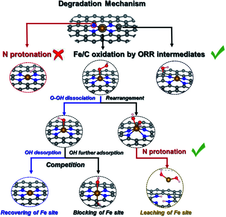
We summarize possible catalyst degradation mechanisms during the ORR. Protonation on an N atom of bare FeNC catalysts is difficult, leaching of the Fe site is also likely to happen, due to successive N protonation that destroys the FeN4 moiety releasing Fe(OH)2 species.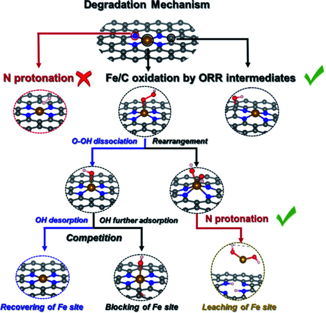
1. Introduction
The oxygen reduction reaction (ORR) at the cathode of Fuel Cells (FCs), as the most critical step heavily limits the total output power density of FCs, because of the sluggish kinetics of ORR. While Pt and Pt-based metals as the best catalysts for ORR are extremely deficient in the Earth's resources.1 To meet the demands for the widespread adoption of FCs, it is necessary to explore non-noble-metal-based catalysts with relatively low cost as alternative electrocatalysts for ORR. In the past ten years, meaningful progress has been achieved, especially for transitional metal-nitrogen-carbon (TMNC) catalysts, such as FeNC,2 ZnNC,3 and CoNC,4 which stand out from other carbon-based catalysts as the most promising substitutable Pt-based ORR catalysts, not only in alkaline media but also in acidic media. At present, the power density of TMNC catalysts is approaching about half that of commercial Pt-based catalysts in membrane electrode assembly (MEA) tests.5 However, numerous challenges still remain before TMNC catalysts will become viable for Proton Exchange Membrane FCs (PEMFCs), of which catalyst instability seems to be the greatest. More specifically, the performance of a PEMFC with an FeNC based cathode typically degrades by 40–80% in the first 100 h of durability testing showing fast degradation of activity.5 Therefore, understanding the degradation mechanisms of TMNC catalysts becomes critically important, especially in acidic media.
Four types of mechanisms have been proposed for the deactivation of an FeNC catalyst in an acidic medium:5–8
(1) Nitrogen species protonation:9 the protonation of highly basic nitrogen groups neighboring the active site, followed by anion adsorption. Herranz et al.9 proposed that the turnover frequency (TOF) value on FeNC active sites should be high when the basic nitrogen groups next to the FeNX site are protonated, but without anion adsorption. But once the anion adsorption took place on an Fe/C site, the TOF value would become low. Dodelet et al.8 speculated that fluorination (which could be regarded as direct anion adsorption) of FeN4 active sites leads to the formation of C–F bonds on some carbon sites and Fe–F bonds on all metal sites, and these bonds induce instability in the FeNC catalyst during FC processing. However, their subsequent research demonstrated that the anion adsorption on FeN4 active sites has no effect on the initial decay in ORR activity, and the hypothesis of the anionic neutralization of the FeN4⋯NH+ site should be abandoned.10 Similarly, Mukerjee et al.11,12 also confirmed that the deactivation of FeNC catalysts does not depend on the anions, and FeN4 exhibits immunity to surface poisoning by some anions.
(2) Carbon/metal oxidation:6 the carbon/metal active sites on the catalyst surface can be attacked by H2O2-derived radicals, which then proceed to induce either a Fenton reaction (Fe2+ + H2O2 + H+ → Fe3+ + ·OH + H2O) or the formation of surface oxidation intermediates. However, this type of deactivation might be partially reversible upon reduction of the catalyst surface. Jaouen et al.7 demonstrated that the FeNC catalyst is structurally stable, but in an acidic medium, it is electrochemically unstable. This is owing to the existence of H2O2 resulting in some untouched Fe-based catalytic sites and oxidation of the carbon surface by which TOF should be decreased. The TOF is then recovered upon electrochemical reduction of the carbon surface. Their results also confirmed that it is the peroxide-derived reactive oxygen species (such as OH, OOH and O radicals), rather than molecular H2O2, that cause the degradation of the FeNC catalyst.
(3) Demetalation of the Fe atom or FeNX center:13 the demetalation of Fe atoms or FeNX moieties on the catalyst surface by chemical/electrochemical corrosion or by degradation of the carbon framework. Mayrhofer et al.13 demonstrated that carbon oxidation and demetalation of Fe species happen at high (>0.9 V) and low (<0.7 V) potentials, respectively. Even though Fe demetalation can potentially cause damage to the FC system, they did not think that Fe demetalation could lead to decay in ORR activity. Conversely, Chenitz et al.14 proposed that the demetalation of the FeNX center is independent of FC potential. Based on the Le Chatelier principle, the FeNC/Fe2+ thermodynamic equilibrium would shift toward the formation of more Fe2+ while water runs into the micropores, which should be responsible for the fast decay of FC performance.
(4) Water flooding:10 water runs into the pores of the catalysts and impedes the transport of oxygen into the cathode. Dodelet et al.10 found that the most active FeNX sites, that occupy the micropores of catalysts, are involved in the initial rapid decay of catalytic activity in FCs due to the water flooding of catalyst microspores. However, Banham et al.15 considered that micropore flooding cannot be associated with the observed destruction by investigating the micropore flooding in situ before and after stability testing. This result suggested that the ‘deactivation’ and/or ‘loss’ of key active sites lead to kinetic losses, and the oxidation of active sites/carbon should be the most probable cause.
In particular, more than one of these deactivation mechanisms may occur in parallel during stability or durability testing of FCs, which significantly enhances the complexity of the degradation process and makes it a big challenge to reveal the underlying dominant one. Presently, there are a lot of unanswered questions: for example, which degradation mechanism is primarily responsible for the fast decay of ORR catalytic activity? What causes the permanent damage to the FeNC catalyst, such as the loss of active sites and demetalation of Fe sites? How do the degradation mechanisms interact with each other or do they combine together to destroy the FeNC active site and cause the loss of activity? Thus, this necessitates a comprehensive recognition of these possible degradation mechanisms and their contribution to the decay of ORR catalytic activity for an in-depth understanding of the stability of TMNC catalysts.
Here, we have combined density functional theory (DFT) with ab initio molecular dynamics (AIMD) to probe the thermodynamic description of each possible degradation mechanism and the dynamic structural evolution of the active sites of FeNC during ORR, and we try to illuminate their interaction and contribution to the destruction of active sites and the decay of ORR activity. We chose the FeN4 moiety as the active site model at the atomic level and constructed an FeNC periodic slab model without defects or edges to undertake the following study. This is because FeN4 is the dominant existing form in FeNC catalysts produced by a pyrolysis method,5,16–18 and is the most-studied active site showing high ORR activity.6,9,11,19 Though the defects or edges might enhance the ORR activity of FeNC catalysts by increasing the density of active sites or changing the electronic structure,20 the ambiguous interaction between defects/edges and active sites makes the atomically active site structure more complex and varied, and then it is hard to explore the degradation mechanism directly caused by the FeN4 moiety.
In this work, firstly, we calculated each proposed degradation mechanism, including protonation of N sites and oxidation of Fe sites (FeOR) by ORR intermediates, to clarify the possibility that each mechanism happened during ORR in terms of thermodynamics. Then, we comprehensively investigated the dynamic structural evolution of the FeN4 moiety under the effect of different degradation mechanisms to reveal their interactions and influences on triggering the demetalation of the FeN4 moiety. Meanwhile, we unveiled the crucial intermediate bridging the competitive relationship between ORR and FeOR, and defined a trade-off potential (URHETMOR) to describe the anti-oxidation ability of metal active sites.
2. Methods
Density functional theory (DFT) was implemented in Vienna Ab Initio Simulation Package (VASP) code.21 In order to simulate an H2O solvent environment, the thermodynamic zero-point energy was calculated with the implicit solvation model—VASPsol.22 The Perdew–Burke–Ernzerhof (PBE) functional within the generalized gradient approximation (GGA) was adopted to describe electronic exchange–correlation energy. The ionic cores were described with the projector augmented wave (PAW) method.
The 6 × 6 supercell doped-graphene structure was separated by a vacuum of 15 Å height from its neighbours. An energy cutoff of 500 eV was used for the plane wave basis, and the K-points were set to 2 × 2 × 1. It is generally recognized that the localized 3d electron correlation for a transition metal in the fourth period can be described by the DFT + U method.23 Here we applied DFT + U through a rotationally invariant approach with the corresponding U–J values ((U–J)Fe = 3.29 and (U–J)Zn = 4.12).24 All of the calculations were continued until the force and energy had converged to less than 0.02 eV Å−1 and 10−5 eV, respectively.25
The AIMD simulations were performed using the canonical ensemble (NVT) and Nosé–Hoover thermostat method at 300–500 K (from room temperature to FC operating temperature and even higher) and lasted for 10–15 ps, in which the timestep is set as 1 fs, by increasing the hydrogen mass to 2 atomic mass units (H/D-exchange) to reduce the computational cost.26–30
3. Results and discussion
3.1. Nitrogen species protonation
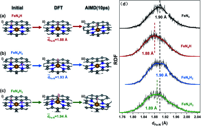
The protonation of N sites in the FeN4 moiety was calculated by combined DFT and AIMD simulations to elucidate the details of the change in Fe–N bonds (Fig. 1). And a set of atomic coordinates obtained as a result of the AIMD simulations at 500 K (Fig. S1–S3†), were used to calculate radial distribution functions31 (RDF, Fig. 1d). In Fig. 1a, for an FeNC slab with one adsorbed H atom on the N site (Fig. 1ai, FeN4H), *H would spontaneously shift from the N to the Fe site after DFT optimization (Fig. 1aii). Meanwhile, this structure shows dynamic stability under a 10 ps AIMD process in implicit solvation (Fig. 1aiii and S4a†) and explicit solvation (Fig. S5 and S6, Video S1a†). And both implicit and explicit solvation show similar effects on the dynamic stability of the FeNC structure. Once the number of adsorbed H increases to 2, as shown in Fig. 1b and S2† (FeN4H2), *H not only bonds with the Fe site, but also forms an H–H bond, and then diffuses to the vacuum layer as molecular H2 within 0.1 ps which is shown in Fig. S4b.† When the third H is introduced into the system (Fig. 1ci, FeN4H3), the Fe site binds two *H atoms and the N site adsorbs one *H (Fig. 1cii), showing thermodynamic stability. While, in AIMD, *H2 is desorbed from the Fe site after 0.5 ps and then *H on the N site migrates to the Fe site at the same time, indicating the unstable protonation of N (Fig. S3 and S4c†). In addition, the Fe–N distance distribution (Fig. 1d) shows that the adsorbed proton results in a negative shift of about 0.01–0.02 Å for the Fe–N peak value compared to that of the bare FeNC model (black dotted line, 1.90 Å), meaning the Fe–N bond is strengthened slightly. Therefore, on a bare FeNC surface, protonation of N in the FeN4 moiety is unlikely to occur, and simultaneously a proton prefers to bind with the Fe site which has almost no effect on the structure of the FeN4 moiety.
Fig. 1. (a–c) The initial, thermodynamic (DFT), and dynamic (AIMD) optimized configurations of protonation on an FeNC catalyst. (d) The radial distribution functions (RDFs) for the Fe–N distance in an FeNC catalyst with different numbers of protons at 500 K within 10 ps of the AIMD simulation, where the white, gray, blue, and yellow balls represent H, C, N, and Fe atoms, respectively.
3.2. Thermodynamic mechanism of Fe oxidation by ORR intermediates
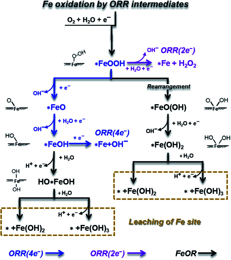
During the ORR process, the Fe active sites on the FeNC catalyst surface would be attacked or oxidized by ORR key intermediates (OOH, O, OH and H2O32), forming surface oxidation intermediates or proceeding in a Fenton reaction, even leading to the permanent loss of Fe sites or FeNX centers. Here, as shown in Scheme 1, we canvassed all possible reactions on the Fe site, including ORR processes, and FeOR by ORR intermediates, in which *FeOH, HO*FeOH and *Fe(OH)2 are oxidation intermediates; while *+Fe(OH)2 and *+Fe(OH)3 represent the leaching of the Fe site.
Scheme 1. A schematic depiction of Fe site oxidation mechanisms involving ORR intermediates on an FeNC catalyst.
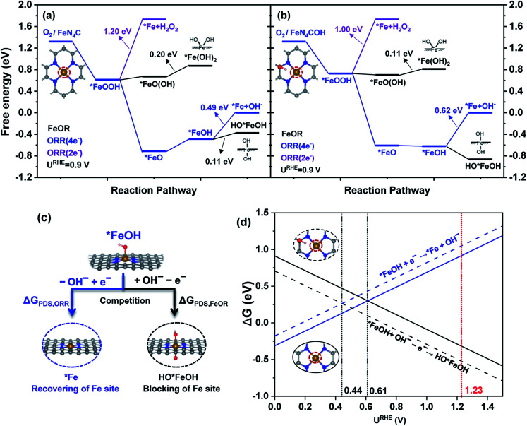
Our previous work33 verified that the C sites can also be oxidized/attacked by O or OH (COR) on a doped-graphene surface during ORR. For an FeNC catalyst, COR screening reveals that the C site near the N atom (Fig. S7†) has the lowest OH adsorption free energy (ΔG) value (Fig. S8†), meaning the highest probability of OH attacking. Based on this, as shown in Fig. 2, the FeOR thermodynamic mechanism and ORR mechanism on FeNC with and without C site binding with OH (FeN4COH and FeN4C) were calculated, respectively, according to Scheme 1. Note that we only focus on the oxidation intermediates of Fe, i.e. HO*FeOH and *Fe(OH)2, in the Gibbs free energy diagrams instead of the leaching production of the Fe site.
Fig. 2. Free energy diagrams of the ORR and FeOR mechanisms at an electrode potential of URHE = 0.9 V for (a) FeN4C and (b) FeN4COH; (c) the competitive relationship between the ORR and FeOR; and (d) the ΔG values of competitive reactions for the ORR and FeOR as a function of URHE.
In Fig. 2a, at URHE = 0.9 V (about the half-wave potential of the FeNC catalyst when catalyzing ORR18), the formation of *FeOOH is spontaneous, and *FeOOH acts as a bifurcation point, directing the following reactions branched to ORR(2e−), ORR(4e−) and FeOR. Specifically, the successive step of ORR(2e−) is proton and electron transfer (PET) to form H2O2, which is the PDS of ORR(2e−) with a ΔGPDS value of 1.20 eV. The following ORR(4e−) steps include the downhill dissociation of O–OH to generate *FeO, and continuous PET to desorb OH. Among these steps, OH desorption is the PDS of ORR(4e−) with a ΔGPDS of 0.49 eV. The first FeOR path starts from the rearrangement of *FeOOH, which subsequently leads to the formation of *FeO(OH) oxidation species. The successive protonation step to form *Fe(OH)2, in which 2OH species are adsorbed on the same side of the FeN4 moiety, is the PDS with a ΔGPDS of 0.20 eV. Apart from *FeOOH, *FeOH is the second bifurcation point connecting the OH desorption in ORR(4e−) and the further OH adsorption in the second FeOR path. The further OH adsorption on *FeOH to form HO*FeOH is the PDS with a ΔGPDS of 0.11 eV. Because the ΔGPDS value of FeOR is much lower than that of ORR(2e−) and ORR(4e−) at URHE = 0.9 V, the Fe site of the FeN4 moiety is more likely to be oxidized by ORR intermediates instead of catalyzing ORR.
Once the near C site of the FeN4 moiety binds with OH, in Fig. 2b, the ΔGPDS value of *Fe(OH)2 formation decreases to 0.11 eV, and the formation of HO*FeOH becomes spontaneous because of the significantly decreased ΔG value. While OH desorption from *FeOH in ORR(4e−) becomes more difficult due to the enhanced ΔGPDS value (0.62 eV). Then the oxidation of near C sites can further boost FeOR by ORR intermediates and suppress ORR (4e−).
It can be seen that *Fe(OH), *Fe(OH)2 and HO*FeOH are the dominant intermediates, and would have a great influence on stability and ORR activity. Among them, the *FeOH intermediate is key, connecting the PDS of ORR(4e−) (*FeOH + e− → *Fe + OH−, OH desorption) and the PDS of FeOR (*FeOH + OH− → OH*FeOH + e−, OH further adsorption/attack), corresponding to the recovering and blocking of Fe active sites, respectively. As shown in Fig. 2c, the competitive relationship can be described by comparing the ΔG values of the two reactions. When the ΔGPDS of ORR(4e−) is equal to that of FeOR at a certain electrode potential, the OH desorption and the further OH adsorption of *FeOH have the same probability. Then, we define the certain electrode potential as a trade-off potential (URHETMOR, the process of derivation is listed in ESI†) to indicate the competitive relationship between ORR and FeOR and describe the anti-oxidation ability of the Fe site.
As shown in Fig. 2d, for the FeN4C surface, the ΔG intersection of OH desorption and further OH adsorption corresponds to the trade-off potential value, which is 0.61 V. On the left-hand side (URHE < 0.61 V), the ΔG of OH desorption is lower than that of further OH adsorption; while on the right-hand side (URHE > 0.61 V), the ΔG of OH desorption becomes larger than that of further OH adsorption, suggesting that the blocking of the Fe site is more likely to occur than recovery of the Fe site when the electrode potential is higher than 0.61 V. In the case of FeN4COH, URHETMOR decreases to 0.44 V, showing that OH desorption needs a higher overpotential to compete with further OH adsorption, and the Fe active site is prone to be occupied by OH at a wider potential range. Then, the URHETMOR indicates the turning point at which the reaction changes from further OH adsorption to OH desorption with decreasing URHE. And the more negative the URHETMOR value (smaller than the ORR equilibrium potential, 1.23 V vs. RHE), meaning the poorer the competitive ability of OH desorption with further OH adsorption on the Fe site, and the lower the anti-oxidation ability. Thoroughly regulating the balance of adsorption/desorption of one or more OH species on the Fe site could shift the URHETMOR to positive, benefitting the recovery of the active site and improving the stability and activity simultaneously.
Hence, from the thermodynamic point of view, Fe site oxidation by ORR intermediates is thermodynamically feasible. And the blocking of the Fe site could occur more smoothly than ORR(4e−) or ORR(2e−) when URHE is higher 0.61 V.
3.3. The trigger for the demetalation of the FeN4 moiety
Although the thermodynamic mechanism demonstrates that the formation of *FeOH, HO*FeOH and *Fe(OH)2 oxidation intermediates during ORR is inevitable, it is still unknown whether the Fe site would leach or not. To probe the possibility of demetalation of the FeN4 moiety, these key intermediates should be further researched.
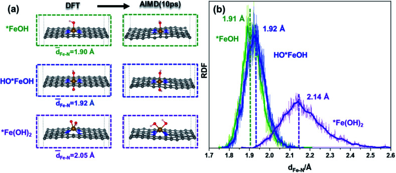
The structures of *FeOH, HO*FeOH and *Fe(OH)2 were calculated by DFT calculation and AIMD simulation to unveil the influence of OH species on the FeN4 moiety. The DFT optimized configurations in Fig. 3a show that the structure of *Fe(OH)2 is more distorted than those of *FeOH or HO*FeOH, because the same side adsorbed OH species on the Fe site, damaging the framework plane. And the Fe–N bond lengths of the three intermediates in DFT optimization are in good agreement with the statistic of the Fe–N distance in AIMD. In Fig. 3b, the Fe–N lengths in the *FeOH and HO*FeOH system (1.91 and 1.92 Å, respectively) are close to that in the bare FeNC model (1.90 Å, Fig. 1d), while the largest Fe–N length in the *Fe(OH)2 structure of 2.14 Å is significantly elongated, demonstrating that the same side adsorbing OH species would weaken the interaction of Fe–N. Furthermore, *Fe(OH)2 with COR (*Fe(OH)2–C(OH)X (X = 1 and 2)) similarly shows an elongated Fe–N distance in the range of 1.97 to 2.12 Å (Fig. S9†). The structural deformation of the FeN4 moiety determines that *Fe(OH)2 must be the crucial intermediate, which can quite possibly induce the further destruction of the FeN4 moiety. However, AIMD simulation finds that *Fe(OH)2 is dynamically stable due to the almost unchanged structure after 10 ps of AIMD simulation, even in explicit solvation (Fig. S10 and S11, Video S1b†). Therefore, other factors, that directly cause the breaking of the Fe–N bond and then leaching of the Fe site, need to be revealed in detail.
Fig. 3. (a) DFT and AIMD optimized configurations of *FeOH, HO*FeOH, and *Fe(OH)2 intermediates in an FeNC catalyst, and (b) the RDFs of the Fe–N distance in *FeOH, HO*FeOH, and *Fe(OH)2 intermediates at 500 K within 10 ps of AIMD simulations.
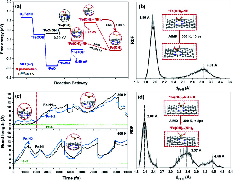
Deep analysis of the electronic structure about *FeOH, HO*FeOH, *Fe(OH)2, including ICOHP (Fig. S12†) and Bader charge (Table S1†), indicates that *Fe(OH)2 with fewer electrons between Fe–N bonds causes N with a likely pyridine N property. This means that protonation on N in *Fe(OH)2 would take place. DFT optimization demonstrates that the protonation of N in *Fe(OH)2 is stable, while HO*FeOH with oppositely adsorbed OH species cannot cause the protonation of N, which instead steps up the desorption of OH due to the combination of OH and proton to form H2O (Fig. S13†). In Fig. 4a, the DFT calculated result reveals that the first protonation of N in *Fe(OH)2 (*Fe(OH)2–NH) is thermodynamically favorable (ΔG < 0 eV), in which two of the four Fe–N bonds dissociate and *Fe(OH)2 stands out in the 2D framework plane. The second protonation of N (*Fe(OH)2–(NH)2) further destroys the third Fe–N bond leaving only one Fe–N bond. Although the formation of *Fe(OH)2–(NH)2 is an endothermic process, the energy barrier of 0.77 eV is close to 0.75 eV,34 indicating that the reaction can be surmounted easily by tuning the reaction conditions, such as temperature, species concentration, and electrode potential.
Fig. 4. (a) The free energy diagram of FeOR at an electrode potential of UNHE = 0.9 V involving ORR intermediates and an FeNC catalyst; (b, d) the RDFs of Fe–N distance in *Fe(OH)2–NH and *Fe(OH)2–(NH)2 systems obtained from AIMD simulations at 300 K; and (c) the AIMD trajectories of Fe–N and Fe–O distances of the *Fe(OH)2–NH + H model at 300 K and 400 K.
AIMD simulation further shows that the formation of *Fe(OH)2–NH is dependent on the direction of proton adsorption. As shown in Fig. S14 and Video S2a,† one proton interacts with N on the same side of OH adsorption in the *Fe(OH)2 system, and H would combine with OH and form H2O to benefit ORR(4e−). While, when the proton attacks N from the opposite side of the adsorbed OH species in the *Fe(OH)2 system (Video S2b†), the protonation of the N atom then breaks two Fe–N bonds spontaneously. As shown in Fig. 4b and S15,† the *Fe(OH)2–NH structure exhibits dynamic stability during the AIMD process within 15 ps at 300, 400 or even 500 K (Fig. S16 and S17†). The Fe–N RDF in *Fe(OH)2–NH shows two peak values at 1.96 Å (Fe–N bond) and 3.04 Å, respectively, which is consistent with the DFT results. In the AIMD trajectories of Fig. 4c and S18,† *Fe(OH)2–(NH)2 is metastable, and can only survive for ∼2 ps at 300 K, in which the third Fe–N bond dissociates with one elongated Fe–N bond remaining (Fig. 4d). After 2 ps, the only remaining Fe–N bond in *Fe(OH)2–(NH)2 is gradually broken, and Fe(OH)2 detaches from the graphene plane and diffuses into the vacuum layer. Furthermore, when the temperature is raised to 400 or even 500 K (Fig. S19 and S20†), the Fe–N bonds in *Fe(OH)2–(NH)2 dissociate immediately and release Fe(OH)2 species.
The above results reveal that, for the demetalation of an FeNC catalyst in an acidic medium, the formation of *Fe(OH)2 is an essential prerequisite, which results in N protonation in the FeN4 moiety; and the subsequent N protonation becomes the crucial step, which by combining with an *Fe(OH)2 intermediate, exacerbates the destruction of the FeN4 moiety, and triggers the leaching of Fe.
3.4. The possible proposed degradation mechanisms
Scheme 2 summarizes the possible proposed degradation mechanisms during ORR. Due to the stable Fe–N bond, protonation on the N atom in a bare FeNC catalyst is difficult. The Fe/C site oxidation by ORR intermediates is inevitable. And the leaching of the Fe site is also likely to happen. An *FeOH intermediate connecting the recovery and blocking of the Fe site can indicate the competitive relationship between the ORR and FeOR. And the formation of an *Fe(OH)2 intermediate as the prerequisite can denote the possibility of demetalation of the FeN4 moiety.
Scheme 2. The pathway of the degradation mechanism of an FeNC catalyst.
The ORR theoretical activity listed in Fig. S21† shows that the appropriate occupation of OH on the Fe site (*FeOH) would decrease the ΔGmax,ORR value of the Fe active site from 0.82 eV to 0.29 eV, thus greatly enhancing ORR activity. The excessive occupation of OH, forming *Fe(OH)2 or OH*FeOH, blocks the Fe active site and would further increase the ΔGmax,ORR of the C sites to ∼1.2 eV, which decreases the ORR activity. However, the recoverable Fe site by partial reduction of the catalyst surface cannot cause the permanent loss of activity. While the leaching of the Fe site in the FeN4 moiety causes the formation of CNx, and increases the ΔGmax,ORR of the C sites in CNx to >1.3 eV, leading to an irreversibly sharp decline in ORR activity. This verifies that demetallation of the FeN4 moiety should be the major reason behind the rapid initial irreversible loss of performance of FeNC catalysts. In other words, the formation of an *Fe(OH)2 intermediate and its induced successive N protonation are combined together to cause the permanent loss of ORR activity. It is therefore logical to speculate that *Fe(OH)2 is a key intermediate to indicate the possibility of degradation of the FeNC catalyst. In addition, it also explains why the stability of FeNC for ORR in acid faces a severe loss compared to that in alkaline media. The absence of protons in alkaline solution would only initiate the partially reversible deactivation of the FeN4 moiety on the FeNC catalyst.
Considering the degradation mechanism and the decline of activity, it is feasible to identify the anti-oxidation ability of TMNC catalysts by researching the formation of *TM(OH)X (X = 1 and 2) during ORR, and is also even feasible to decrease the leaching of TM sites by eliminating the formation of a *TM(OH)2 intermediate. To verify the practicability of the above guidelines, we further calculated the oxidation mechanism of ZnNC during ORR, referring to our previous experimental results.3 In Fig. S22,† the free energy diagram of *Zn(OH)2 and *ZnOH shows that ZnNC prefers to be occupied by OH instead of leaching Zn due to the rather difficult formation of *Zn(OH)2. The energy barriers for rearrangement of *ZnO(OH) and further oxidation of *ZnOH to *Zn(OH)2 are higher than ∼1 eV. Meanwhile, the *ZnOH intermediate also cannot be oxidized in the form of HO*ZnOH. And the trade-off potential URHETMOR of ZnNC is higher than 1.23 V. Then, compared to FeNC, ZnNC exhibits much higher anti-oxidation ability, which is in agreement with our previous experimental results.3 That is, the ZnNC catalyst largely maintains its ZnNX active sites after an accelerated stress test, and shows only a slight decrease in ZnNX content and a relatively small decrease in pyridinic-N content in an acidic medium, whereas the FeNC catalyst shows a rather large decrease in FeNX and pyridinic-N content. The half-wave potential of ZnNC decayed from 0.746 V to 0.726 V after 1000 CV cycles, whereas a significantly larger decay (from 0.743 to 0.712 V) was observed for the FeNC catalyst.3
However, due to the too weak OH adsorption, ZnNC shows poorer ORR intrinsic activity than FeNC. This means that, to screen TMNC catalysts with high activity and stability, it is not only necessary to consider the volcano relationship between *OH adsorption and ORR activity,35,36 but the trade-off relationship between ORR activity and anti-oxidation ability should also be considered.
4. Conclusions
The present work provided a DFT + AIMD approach to investigate the possibility of each degradation mechanism relating to FeN4 happening during the ORR with the aim of depicting the complete thermodynamic mechanism and the dynamic structural evolution of an FeNC catalyst. The calculation results found that N protonation of bare FeNC is difficult, while Fe/C oxidation by ORR intermediates is inevitable. *FeOH as a key intermediate can describe the competitive relationship between catalyzing the ORR(4e−) and FeOR, and FeOR can surpass the ORR(4e−) when the electrode potential is higher than the trade-off potential URHETMOR of 0.61 V. The formation of *Fe(OH)2 from the FeN4 moiety leads to favorable N protonation. And the *Fe(OH)2 intermediate interacts with successive N protonation to further destroy the FeN4 moiety, thus largely leading to the leaching of the Fe site in the form of Fe(OH)2. The change in the intrinsic ORR activity determines that the demetalation of an FeNC catalyst is the underlying dominant reason for activity decay in an acidic medium. Meanwhile, our research has presented a trade-off potential to describe the anti-oxidation abilities of TMNC catalysts.
Data availability
Source data are provided with this paper. Additional methods and results are provided in the ESI.†
Author contributions
Na Yang and Lanlan Peng performed the theoretical calculations and the interpretation, Li Li and Na Yang wrote this manuscript, Zidong Wei directed the project and finalized the manuscript, other authors contributed to the revision.
Conflicts of interest
There are no conflicts of interest.
Supplementary Material
Acknowledgments
This work was supported by the National Key Research and Development Program of China (2019YFB1504500) and National Natural Science Foundation of China (No. 21822803, No. 21761162015, No. 91834301, No. 21576032, and No. 52021004).
Electronic supplementary information (ESI) available. See DOI: 10.1039/d1sc02901k
Notes and references
- Tian N. Zhou Z. Y. Sun S. G. Ding Y. Wang Z. L. Science. 2007;316:732–735. doi: 10.1126/science.1140484. [DOI] [PubMed] [Google Scholar]
- Ratso S. Sahraie N. R. Sougrati M. T. Kaarik M. Kook M. Saar R. Paiste P. Jia Q. Y. Leis J. Mukerjee S. Jaouen F. Tammeveski K. J. Mater. Chem. A. 2018;6:14663–14674. doi: 10.1039/C8TA02325E. [DOI] [Google Scholar]
- Li J. Chen S. G. Yang N. Deng M. M. Ibraheem S. Deng J. H. Li J. Li L. Wei Z. D. Angew. Chem., Int. Ed. 2019;58:7035–7039. doi: 10.1002/anie.201902109. [DOI] [PubMed] [Google Scholar]
- Jaouen F. Dodelet J. P. Electrochim. Acta. 2007;52:5975–5984. doi: 10.1016/j.electacta.2007.03.045. [DOI] [Google Scholar]
- Shao Y. Dodelet J. P. Wu G. Zelenay P. Adv. Mater. 2019;31:1807615–1807622. doi: 10.1002/adma.201807615. [DOI] [PubMed] [Google Scholar]
- Kumar K. Dubau L. Mermoux M. Li J. Zitolo A. Nelayah J. Jaouen F. Maillard F. Angew. Chem., Int. Ed. 2020;59:3235–3243. doi: 10.1002/anie.201912451. [DOI] [PubMed] [Google Scholar]
- Choi C. H. Lim H. K. Chung M. W. Chon G. Sahraie N. R. Altin A. Sougrati M. T. Stievano L. Oh H. S. Park E. S. Luo F. Strasser P. Drazic G. Mayrhofer K. J. J. Kim H. Jaouen F. Energy Environ. Sci. 2018;11:3176–3182. doi: 10.1039/C8EE01855C. [DOI] [Google Scholar]
- Zhang G. X. Yang X. H. Dubois M. Herraiz M. Chenitz R. Lefevre M. Cherif M. Vidal F. Glibin V. P. Sun S. H. Dodelet J. P. Energy Environ. Sci. 2019;12:3015–3037. doi: 10.1039/C9EE00867E. [DOI] [Google Scholar]
- Herranz J. Jaouen F. Lefevre M. Kramm U. I. Proietti E. Dodelet J. P. Bogdanoff P. Fiechter S. Abs-Wurmbach I. Bertrand P. Arruda T. M. Mukerjee S. J. Phys. Chem. C. 2011;115:16087–16097. doi: 10.1021/jp2042526. [DOI] [PMC free article] [PubMed] [Google Scholar]
- Zhang G. Chenitz R. Lefèvre M. Sun S. Dodelet J. P. Nano Energy. 2016;29:111–125. doi: 10.1016/j.nanoen.2016.02.038. [DOI] [Google Scholar]
- Strickland K. Pavlicek R. Miner E. Jia Q. Y. Zoller I. Ghoshal S. Liang W. T. Mukerjee S. ACS Catal. 2018;8:3833–3843. doi: 10.1021/acscatal.8b00390. [DOI] [Google Scholar]
- Tylus U. Jia Q. Hafiz H. Allen R. J. Barbiellini B. Bansil A. Mukerjee S. Appl. Catal., B. 2016;198:318–324. doi: 10.1016/j.apcatb.2016.05.054. [DOI] [Google Scholar]
- Choi C. H. Baldizzone C. Grote J. P. Schuppert A. K. Jaouen F. Mayrhofer K. J. Angew. Chem., Int. Ed. 2015;54:12753–12757. doi: 10.1002/anie.201504903. [DOI] [PubMed] [Google Scholar]
- Chenitz R. Kramm U. I. Lefevre M. Glibin V. Zhang G. X. Sun S. H. Dodelet J. P. Energy Environ. Sci. 2018;11:365–382. doi: 10.1039/C7EE02302B. [DOI] [Google Scholar]
- Choi J. Y. Yang L. Kishimoto T. Fu X. Ye S. Chen Z. Banham D. Energy Environ. Sci. 2017;10:296–305. doi: 10.1039/C6EE03005J. [DOI] [Google Scholar]
- Huang X. Shen T. Zhang T. Qiu H. Gu X. Ali Z. Hou Y. Adv. Energy Mater. 2019;10:1900375–1900395. doi: 10.1002/aenm.201900375. [DOI] [Google Scholar]
- Abdelkareem M. A. Sayed E. T. Mohamed H. O. Obaid M. Rezk H. Chae K. J. Prog. Energy Combust. Sci. 2020;77:100805–100856. doi: 10.1016/j.pecs.2019.100805. [DOI] [Google Scholar]
- Wan C. Duan X. Huang Y. Adv. Energy Mater. 2020;10:1903815–1903833. doi: 10.1002/aenm.201903815. [DOI] [Google Scholar]
- Li Y. Liu X. Zheng L. Shang J. Wan X. Hu R. Guo X. Hong S. Shui J. J. Mater. Chem. A. 2019;7:26147–26153. doi: 10.1039/C9TA08532G. [DOI] [Google Scholar]
- Wang X. Jia Y. Mao X. Liu D. He W. Li J. Liu J. Yan X. Chen J. Song L. Du A. Yao X. Adv. Mater. 2020;32:2000966–2000975. doi: 10.1002/adma.202000966. [DOI] [PubMed] [Google Scholar]
- Zhao J. Chen Z. J. Am. Chem. Soc. 2017;139:12480–12487. doi: 10.1021/jacs.7b05213. [DOI] [PubMed] [Google Scholar]
- Li L. S. Martirez J. M. P. Carter E. A. ACS Catal. 2020;10:12841–12857. doi: 10.1021/acscatal.0c03140. [DOI] [Google Scholar]
- Chen K. Liu K. An P. Li H. Lin Y. Hu J. Jia C. Fu J. Li H. Liu H. Lin Z. Li W. Li J. Lu Y. R. Chan T. S. Zhang N. Liu M. Nat. Commun. 2020;11:4173–4180. doi: 10.1038/s41467-020-18062-y. [DOI] [PMC free article] [PubMed] [Google Scholar]
- Xu H. Cheng D. Cao D. Zeng X. C. Nat. Catal. 2018;1:339–348. doi: 10.1038/s41929-018-0063-z. [DOI] [Google Scholar]
- Zhou S. Yang X. Xu X. Dou S. X. Du Y. Zhao J. J. Am. Chem. Soc. 2020;142:308–317. doi: 10.1021/jacs.9b10588. [DOI] [PubMed] [Google Scholar]
- Tang J. Qiu R. Z. Chen J. F. Ao B. Y. J. Alloys Compd. 2020;834:155113–155118. doi: 10.1016/j.jallcom.2020.155113. [DOI] [Google Scholar]
- Jaouen F. Marcotte S. Dodelet J. P. Lindbergh G. J. Phys. Chem. B. 2003;107:1376–1386. doi: 10.1021/jp021634q. [DOI] [Google Scholar]
- Zhong L. Zhang L. Li S. ACS Mater. Lett. 2020;3:110–120. doi: 10.1021/acsmaterialslett.0c00419. [DOI] [Google Scholar]
- Zhao X. Liu Y. J. Am. Chem. Soc. 2020;142:5773–5777. doi: 10.1021/jacs.9b13872. [DOI] [PubMed] [Google Scholar]
- Cheng T. Xiao H. Goddard W. A. Proc. Natl. Acad. Sci. U.S.A. 2017;114:1795–1800. doi: 10.1073/pnas.1612106114. [DOI] [PMC free article] [PubMed] [Google Scholar]
- Liu J. C. Tang Y. Chang C. R. Wang Y. G. Li J. ACS Catal. 2016;6:2525–2535. doi: 10.1021/acscatal.6b00021. [DOI] [Google Scholar]
- Wang Y. Yi M. Wang K. Song S. Q. Chin. J. Catal. 2019;40:523–533. doi: 10.1016/S1872-2067(19)63314-0. [DOI] [Google Scholar]
- Yang N. Peng L. Li L. Li J. Wei Z. Phys. Chem. Chem. Phys. 2019;21:26102–26110. doi: 10.1039/C9CP04691G. [DOI] [PubMed] [Google Scholar]
- Liu Z. P. Hu P. J. Am. Chem. Soc. 2003;125:1958–1967. doi: 10.1021/ja0207551. [DOI] [PubMed] [Google Scholar]
- Peng J. He Y. Zhou C. Su S. Lai B. Chin. Chem. Lett. 2021;32:1626–1636. doi: 10.1016/j.cclet.2020.10.026. [DOI] [Google Scholar]
- Chen C. Zhang X. Zhou Z. Zhang X. Sun S. Acta Phys. Chim. Sin. 2017;33:1875–1883. [Google Scholar]
Associated Data
This section collects any data citations, data availability statements, or supplementary materials included in this article.
Supplementary Materials
Data Availability Statement
Source data are provided with this paper. Additional methods and results are provided in the ESI.†


