Abstract
In recent decades, to reduce electromagnetic pollution, scientists focus on finding new microwave absorbers with effective performance, thin thickness, and broad bandwidth. In this work, the nanoparticles of NiFe2O4, X-doped g-C3N4 (M = S, P, and O), and MTiO3 (M = Fe, Mg, and Zn) were successfully synthesized using co-precipitation, specific heat program, and semi-wet sol–gel methods, respectively. The synthesized nanoparticles were utilized as absorption agents and polyester resin as the matrix. Morphology, particle size, crystal structure, and chemical composition of the prepared nanocomposites were characterized by scanning electron microscope (SEM), transmission electron microscope (TEM), X-ray diffractometer (XRD), and energy dispersive X-Ray analysis (EDX), respectively. The microwave absorption performance of the coatings was also investigated by a vector network analyzer (VNA). Moreover, the effect of different parameters on the performance of absorbent coatings was studied by the Taguchi method and optimized to achieve an optimal absorbent. The results showed that the optimal nanocomposite has the reflectance loss (RL) less than − 30 dB (equal to absorption > 99%) at a high-frequency range (8–12 GHz) and 1 mm thickness. Furthermore, the addition of such novel nanoparticles to absorbents resulted in high values of attenuation constant (more than 200 dB/m) at the X-band. Therefore, the polyester coating filled with ZnTiO3, O-doped g-C3N4, and NiFe2O4 nanofillers can be considered a high-efficiency and low-density absorber.
Subject terms: Electrical and electronic engineering, Condensed-matter physics, Materials chemistry
Introduction
Nowadays, electromagnetic pollution (PE) generated by telecommunication and electrical facilities has become a serious problem in people's daily life. Excessive radiation of electromagnetic waves causes adverse effects on human health, the environment, and plant growth. Therefore, the high-performance microwave absorbers have attracted the attention of many researchers in the field of decreasing unwanted emissions of electromagnetic waves1–4. The microwave absorbing materials are divided into: dielectric and magnetic, depending on the reaction mechanism between the absorber and the wave5. Besides, according to the theory of electromagnetic energy transfer, there are two basic requirements for effective microwave absorption: (1) Appropriate impedance matching should be considered between the magnetic loss and the dielectric loss; (2) The wave must be attenuated to a large extent after the incident with the material and transferring from within it. The scientists are still looking for a way to meet both requirements at the same time. According to previous reports, using one material as a microwave absorber cannot meet these two requirements. Meanwhile, the combination of dielectric and magnetic materials can provide a promising solution to improve the performance of the microwave absorbers6–9.
In recent years, spinel ferrites have been widely studied as microwave absorbent materials due to high magnetic permeability, spinel structure, low eddy current losses, and excellent magnetic features. Generally, the spinel ferrites are known by the general formula MFe2O4, where M is the transition metal such as nickel, zinc, magnesium, cobalt, calcium, and manganese. The spinel structure has a space group of R3M10–13. However, the ferrites have a high density; it can be improved by reducing the particle size, which not only decreases the specific gravity but also increases the microwave absorption properties. In particular, the nanoparticles of nickel ferrite (NiFe2O4) with the soft spinel ferrite structure have attracted the attention of many researchers owing to their excellent chemical stability, good thermal stability, modest saturation magnetization, availability, lightweight, and high electrical resistivity. These nanoparticles have also been employed as catalysts, pigment, MRI contrast agents, biomedical agents in drug delivery, photo-magnetic materials, sensors, etc.8,14,15.
Scientists today have conducted in-depth studies to find materials with high dielectric constant16. They can be classified as capacitor materials with high dielectric permittivity such as ceramics17 and microwave dielectric materials with low permittivity such as graphite carbon nitrite18, reduced graphene oxide19,20, carbon nanotube21,22. In the present work, MTiO3 (M = Fe, Mg, and Zn) nanoparticles were applied as dielectric materials with high permittivity. These dielectric materials are titanium-based ceramic oxides that have a space group of R3M. These materials have received much attention in the field of microwave wave absorption due to their outstanding properties such as low density, high thermal stability, and high dielectric constant23–25. On the other hand, conductor fillers, microwave dielectric materials, are widely used in the absorbers to lose electromagnetic energy, such as conductive polymers, graphite, CNT, etc. Among these materials, the graphitic carbon nitride (g-C3N4) has attracted the attention of many researchers as a nonmetallic conductive material due to its unique properties such as high dielectric constant, excellent conductivity, and high specific area. Besides, the g-C3N4 conductivity increases by inserting phosphorus, oxygen, and sulfur atoms into the g-C3N4 lattice structure instead of carbon atoms, which may be due to rising electron motion16,26,27.
In this work, the nanofillers of NiFe2O4, X-doped g-C3N4 (M = S, P, and O), and MTiO3 (M = Fe, Mg, and Zn) were successfully synthesized as the magnetic, conductive, and dielectric materials, respectively. Then, they were inserted into the polyester resin as a substrate. The structure and microwave absorption performance of the synthesized samples were carefully investigated. Moreover, the purpose of this work was to study the impact of different parameters on the performance of prepared absorbers in terms of improving microwave absorption and impedance matching in the X-band while keeping the thickness to a minimum. These parameters include the type of dielectric material, the type of dopant in g-C3N4, the weight ratio of MTiO3:NiFe2O4, and the weight ratio of MTiO3/NiFe2O4: X-doped g-C3N4. According to the results obtained, the synthesized nanocomposite under the optimal conditions has higher attenuation, good impendence matching, and effective absorption in X-band. Therefore, this nanocomposite containing ZnTiO3, O-doped g-C3N4, NiFe2O4, and polyester can be used as an enhanced microwave absorber.
Experimental details
Materials
Ni (NO3)2.6H2O (99%), FeCl3 (99%), NaOH (98%), TiO2 (99.5%), FeSO4.7H2O (98%), ZnSO4.7H2O (98%), MgSO4.7H2O (98%), thiourea (98%), melamine (99.5%), oxalic acid (99%), di-ammonium hydrogen phosphate (99%), citric acid (99.5%), and ethanol (98%) were received from Merck, Germany. Cobalt(II) naphthenate accelerator solution, peroxide hardener, N, N-dimethyl aniline, and polyester resin were purchased from Resitan Co., Iran. All chemicals were used without purification.
Instruments and measurements
The phase structure and crystallinity of the nanofillers were investigated by a Bruker D8 Advance X-ray diffractometer (XRD) with Cu Kα radiation (λ = 1.5418 Å) in the Bragg–Brentano geometry. The scanning electron microscope (SEM, Seron Technology, Gyeonggi-do, Korea) equipped with the energy-dispersive X-ray spectroscope (EDX) was applied to determine the morphology and chemical composition of the prepared nanocomposites. In the last technique, all the samples were prepared with a coating of gold. Analysis and processing of SEM images were performed using the Image J software (version 1.53k; https://imagej.nih.gov/ij/download.html). The distribution of the nanofillers in the composite was confirmed using SEM/EDX elemental maps. Transmission electron microscope (TEM, Philips EM208S 100 kV) was used to examine the sample microstructures. A vector network analyzer (HP8410C, USA) over the frequency domain of 8–12 GHz (X-band) was utilized to measure the scattering parameters of the synthesized samples. For this purpose, the samples were first prepared under indicated conditions by the Taguchi method, and then they were cast on the rectangular molds of 10.2 mm × 22.9 mm × 1 mm.
Synthesis of NiFe2O4 nanoparticles
The nanoparticles of NiFe2O4 were synthesized through the co-precipitation method. First, FeCl3 and Ni (NO3)2.6H2O were dissolved with a molar ratio of 2:1 in a specified amount of distilled water under stirring for half an hour. Then, the aqueous solution of NaOH was slowly added to the mixture as a precipitating agent until the pH reached 11.5. The obtained liquid-sediment was stirred using a magnetic stirrer at 80 °C for 60 min. Finally, the solid product was calcined in a furnace at 800 °C for 5 h. The powder obtained after cooling by a mortar was well ground.
Synthesis of MTiO3 (M = Fe, Mg, and Zn)
The semi-wet sol–gel method was used to prepare nanoparticles of FeTiO3, MgTiO3, and ZnTiO3. In summary, to prepare the FeTiO3 nanoparticles, TiO2, FeSO4⋅7H2O, and citric acid were dissolved with a 2:1:1 molar ratio in distilled water. Then, the resulting solution was heated to 80 °C under stirring for water removal. Finally, the obtained sediment was calcined in a furnace at 800 °C for 8 h. After calcination, the product was well ground to get a uniform powder. Similarly, for the synthesis of MgTiO3, and ZnTiO3 nanoparticles, all of the above steps were repeated except that MgSO4⋅7H2O and ZnSO4⋅7H2O were used instead of FeSO4.7H2O in the initial stage, respectively.
Synthesis of X-doped g-C3N4 (M = S, P, and O) nanoparticles
The nanoparticles of O-g-C3N4, P-g-C3N4, and S-g-C3N4 were prepared using a specific heat program method. According to this method, to prepare the nanoparticles of S-g-C3N4, 10 g of melamine and 6 g of oxalic acid were dissolved in 50 ml of distilled water and ethanol mixture (with a molar ratio of 1:1). Then, the resultant solution was stirred by a magnetic stirrer for 1 h, in which hydrogen interactions between oxalic acid and melamine occurred during this period. The mixture was heated to 100 °C under stirring to remove the solvent. Then, the obtained powder was dried into an oven at 120 °C and calcined into a furnace at 530 °C for 3 h. Finally, the resultant product was washed with a mixture of distilled water and ethanol (with a molar ratio of 1:1) and ground with mortar. Similarly, to the synthesis of P-g-C3N4, and S-g-C3N4, all the above steps were repeated except that di-ammonium hydrogen phosphate and thiourea were used instead of oxalic acid.
Experimental design
The experimental design by the Taguchi method provides a significant reduction in costs, time, and the number of experiments that have been widely used by researchers in recent years. In the Taguchi method, the orthogonal arrays are applied for data analysis and experiment arrangement, depending on the number of selected factors and their levels. Moreover, the signal-to-noise ratio (S/N) is defined as the changes made by a factor to improve the quality, in which the highest S/N is chosen as the optimal conditions28. In this work, the L9 (3^4) orthogonal array was selected (Table 1) according to the number of controllable factors (4) and their variation levels (3), as shown in Table 2. Besides, the higher the better was considered as the quality index, which S/N for each output is obtained by the following equation:
| 1 |
where n is the number of experiments, and Yi is the experiment’s results29. In the present work, each test was performed three times to evaluate the repeatability of the measurements. The statistical analysis of the data was carried out by using Qualitek-4 software (version 15.6+; http://nutek-us.com/wp-dm4.html).
Table 1.
Parameters and their levels in the Taguchi experimental design.
| Parameter | Level | ||
|---|---|---|---|
| 1 | 2 | 3 | |
| The type of dielectric material | Mg | Fe | Zn |
| The type of dopant in g-C3N4 | S | O | P |
| The weight ratio of MTiO3:NiFe2O4 | 1:2 | 1:1 | 2:1 |
| The total weight ratio of MTiO3/NiFe2O4: X-doped g-C3N4 | 1:2 | 1:1 | 2:1 |
Table 2.
L9 (34) orthogonal array.
| Test | Parameters | |||
|---|---|---|---|---|
| 1 | 2 | 3 | 4 | |
| 1 | 1 | 1 | 1 | 1 |
| 2 | 1 | 2 | 2 | 2 |
| 3 | 1 | 3 | 3 | 3 |
| 4 | 2 | 1 | 2 | 3 |
| 5 | 2 | 2 | 3 | 1 |
| 6 | 2 | 3 | 1 | 2 |
| 7 | 3 | 1 | 3 | 2 |
| 8 | 3 | 2 | 1 | 3 |
| 9 | 3 | 3 | 2 | 1 |
Preparation of nanocomposite
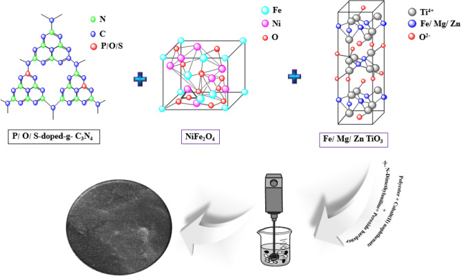
To prepare the absorbent coatings, the filler values in the polyester substrate were first weighed according to Table 2. 0.04 wt% N, N-dimethyl aniline, and 0.05 wt% cobalt(II) naphthenate accelerator solution were added to the polyester resin under stirring for 5 min. Then, specific amounts of fillers were added to the mixture and mixed by a mechanical stirrer until the uniform distribution was obtained. After de-oxygenation, 0.04 wt% of peroxide hardener was added to the mixture and stirred for 2 min. In the long run, the mixture was transferred to the rectangular templates of 10.2 mm × 22.9 mm × 1 mm. The synthesis procedure is schematically shown in Fig. 1.
Figure 1.
Schematic illustration of the synthesis procedure of NiFe2O4, X-doped g-C3N4 (X = S, P, and O), MTiO3 (M = Fe, Mg, and Zn), and polyester nanocomposite.
Results and discussion
Characterizations
The XRD pattern of the prepared NiFe2O4 nanoparticles as the magnetic filler is revealed in Fig. S1 (Supporting Information). The presence of distinct peaks in this figure indicates that the particles are well separated from each other. The diffraction peaks at the different angles of 30.3°, 35.8°, 37.3°, 89.4°, 54.4°, 57.4°, and 62.9° are attributed to Miller indices of (220), (311), (222), (400), (422), (511), and (440), respectively. As a result, this XRD pattern was well-matched with the JCPDS standard file No. 10-0325, which confirm the formation of the single phase of iron oxide with the cubic spinel structure. Moreover, the sharp peaks show that the synthesized nanoparticles have high crystallinity. However, these peaks were broadly distributed, owing to the scattering of X-rays from small particles. In addition, the peaks of NiO and α-Fe2O3 as impurity could be perceived in this pattern, which is probably due to Ni oxidation during the preparation process of NiFe2O4, which causes some Ni ions to be lost, so the presence of excess Fe ions will form α-Fe2O3 particles. Besides, the average crystallite size (L) of the prepared nanoparticles was obtained as 37.22 nm by using the Debye–Scherrer formula, as is shown below:
| 2 |
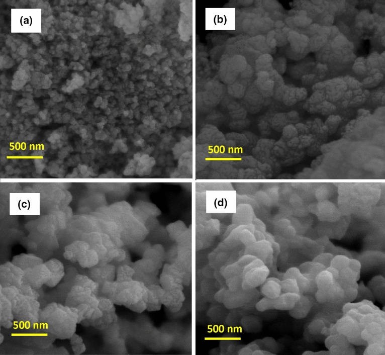
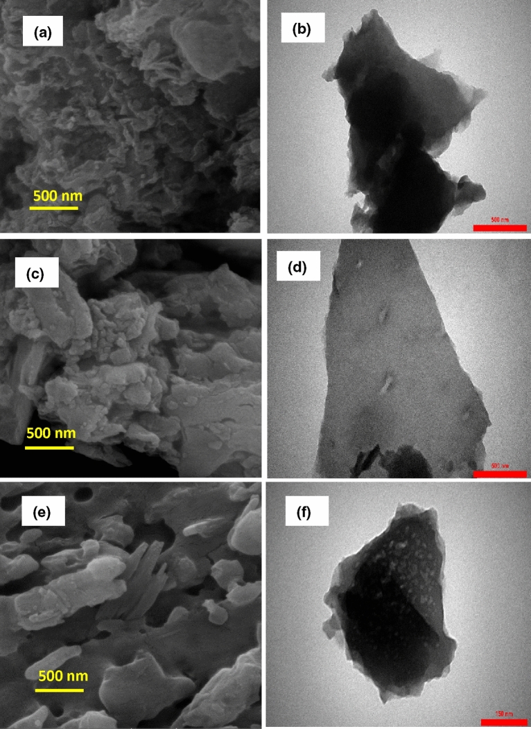
where θ is the angle of diffraction, B is the peak width in a specified amount of 2θ, K is a constant that its value depends on the geometrical shape of the particles30,31. Figure S2a (Supporting Information) shows the X-ray diffraction pattern of the synthesized MgTiO3 nanoparticles. According to this pattern, the main diffraction peaks were detected at (003), (101), (012), (104), (110), (113), (024), (116), (018), (214), and (300), which was matched well with JCPDS card No. 06-0494. In addition to these sharp and narrow peaks indicate the high crystallinity and formation of the cubic structure in MgTiO3 nanoparticles with lattice constants of a = b = 5.05831 Å and c = 13.90858 Å and also bond angles of α = β = 90° and γ = 120°. No peaks of impurities were observed in this pattern, which can ascribe to the high purity of the synthesized MgTiO3 nanoparticles. The crystallite size of MgTiO3 is about 53.94 nm, according to the Scherrer formula. Figure S2b (Supporting Information) displays the XRD pattern of the prepared magnetic nanoparticles of ZnTiO3. The main peaks of ZnTiO3 were observed at (104), (110), (116), (018), and (214), which are in good agreement with the standard file of JCPDS card No. 00-039-0190. The strong and sharp peaks of ZnTiO3 confirm the formation of the cubic morphology with lattice constants of a = b = 5.078 Å and c = 9.27 Å and the high crystallinity. However, the impure peaks related to Zn2TiO4 phases were detected in the XRD pattern due to the annealing at a high temperature. The crystallite size of ZnTiO3 was calculated at 45.31 nm. The XRD pattern of FeTiO3 nanoparticles is revealed in Fig. S2c (Supporting Information). The index peaks located at (103), (015), (006), (115), (300), and (303) are in accordance with the JCPDS card No. 75-1207. The existence of strong and sharp peaks implies the high crystallinity of the synthesized nanoparticles and the formation of the cubic crystal structure with lattice constants of a = 5.141 Å and c = 14.22 Å. However, the impurity peaks ascribed to the anatase and rutile phases of TiO2 crystals appeared in this pattern. Besides, the crystallite size of FeTiO3 was obtained at about 54.80 nm. Figure S3a–c (Supporting Information) represents the X-ray diffraction patterns of O-g-C3N4, S-g-C3N4, and P-g-C3N4 nanoparticles synthesized as conductive materials. The diffraction peaks that appeared at (002) and (100) crystal planes of hexagonal phase g-C3N4 were well matched with JCPDS card No. 01-087-1526. Moreover, these peaks are well compatible with tri-s-triazine-based structural units. It is well known that the different doping atoms into the g-C3N4 structure lead to changes in morphology, crystal structure, particle size, location of diffraction angles, and intensity of peaks. Figure S3a (Supporting Information) reveals the XRD pattern of O-doped g-C3N4 nanoparticles, which have two broad diffraction peaks at 2θ = 13.1° and 27.6°. The main peaks in the O-g-C3N4 nanoparticles are shifted to larger angles than those of graphite nitride carbon (2θ = 12.8° and 27.3°). This is probably due to the high electronegativity of the oxygen atoms relative to the atoms of carbon and nitrogen, resulting in a reduction in the distance between the inner plates32. The X-ray diffraction pattern of S-g-C3N4 nanoparticles is shown in Fig. S3b (Supporting Information). According to this pattern, two diffraction peaks were observed at 2θ = 12.6° and 27.2°. It is clearly visible that the main peaks in the synthesized nanoparticles are transferred to smaller angles than those of graphite nitride carbon. This indicates that the plates’ distance has been increased due to the larger radius of the sulfur atoms33. Figure S3c (Supporting Information) shows the XRD pattern of P-g-C3N4, which has the main peaks at 2θ = 12.5° and 26.9°. The diffraction peaks observed in this pattern are shifted to smaller angles than those of graphite nitride carbon. This shows that the distance between the inner plates has been enhanced owing to the larger radius of the phosphorus atoms34. The crystallite sizes of O-g-C3N4, S-g-C3N4, and P-g-C3N4 nanoparticles were calculated about 14.94, 9.35, and 14.50 nm, respectively (Scherrer formula). Figure 2a represents the SEM images of synthesized NiFe2O4 nanoparticles whose particle size is about 21–29 nm. As can be seen, the severe agglomeration has been occurred between particles, which could own to the intrinsic properties of the magnetic ferrites. The SEM images of MgTiO3, ZnTiO3, and FeTiO3 nanoparticles are shown in Fig. 2b–d, in which their particle sizes are about 18–60, 25–31, and 28–45 nm. As can be seen from the images, the synthesized nanoparticles are observed as the particles agglomerate. This is probably due to the rapid particle growth (the increasing particle size) and reduced particle density at high temperatures. The particle size, chemical composition, and surface morphology of the synthesized O-g-C3N4, S-g-C3N4, and P-g-C3N4 were studied using SEM, TEM, EDX, and the SEM-elemental map analysis, respectively. The SEM, TEM, EDX, and SEM-elemental mapping images of the O-g-C3N4 nanoparticles are indicated in Fig. 3a,b and S4a,b (Supporting Information), respectively. According to the SEM images, the surface of the synthesized nanoparticles is glabrous with a particle size of 26–50 nm. Meanwhile, the TEM image indicates that the O-g-C3N4 nanoparticles have nanosheet morphology with ultrathin thickness. The darker area in the TEM picture is due to multiple nanosheets overlapping. As can be observed from the EDX analysis, the prepared sample consists of carbon, nitrogen, and oxygen atoms, which confirms the successful synthesis of O-g-C3N4. Moreover, the oxygen atoms were well dispersed between carbon and nitrogen atoms, which can be observed from SEM-elemental mapping images (Fig. S4b, Supporting Information). Figure 3c presents the SEM images of the S-g-C3N4 nanoparticles, which have a particle size of about 36–51 nm. Besides, the TEM image of the S-g-C3N4 nanoparticles (Fig. 3d) clearly exhibitions that these nanoparticles have nanosheet morphology and thin diameter. According to the EDX images (Fig. S5a, Supporting Information), the synthesized sample contains the carbon, nitrogen, and sulfur atoms that it is evidence of the successful synthesis of S-g-C3N4 nanoparticles. It is clearly visible from the SEM-elemental mapping images (Fig. S5b, Supporting Information) that the sulfur atoms were localized between carbon and nitrogen atoms. According to the SEM and TEM images in Fig. 3e,f, the P-g-C3N4 nanoparticles have a nanosheet morphology with some irregular cavities and a particle size of 19–26 nm. The darker parts can be related to the accumulation of several flat layers. As can be seen from the EDX and SEM-elemental mapping images (Fig. S6a,b, Supporting Information), the prepared nanocomposite comprises carbon, nitrogen, and phosphorus atoms, and also the phosphorus atoms were well distributed between the nitrogen and carbon atoms; thereby these results confirm the successful synthesis of P-g-C3N4 nanoparticles.
Figure 2.
SEM images of (a) NiFe2O4; (b) MgTiO3; (c) ZnTiO3; (d) FeTiO3 nanoparticles.
Figure 3.
SEM images of (a) O-g-C3N4; (c) S-g-C3N4; (e) P-g-C3N4 nanoparticles; and TEM images of (b) O-g-C3N4; (d) S-g-C3N4; (f) P-g-C3N4.
Microwave-absorbent coatings properties
Reflection loss (RL) is explained as the rate of microwave absorption by nanocomposites. There are three basic ways to calculate this parameter: (1) Transmission-line theory; (2) Radar cross-section measurement; (3) Use of reflection and transition parameters. The transmission-line theory has received much attention from researchers to investigate the microwave absorbing properties by the absorbents. The basis of this method is the design of materials with 100% absorption and zero reflection, so the material impedance must be equal to the free space impedance (Zin = Z0). However, it is an ideal situation, in which no thin material has ever been found under such conditions35. Reflection loss (RL) based on this method is calculated as follows:
| 3 |
| 4 |
where Zin and Z0 are the material impedance and the free space impedance, respectively; is the complex magnetic permeability (); is the complex dielectric permittivity ()36,37. Figure 4 presents the reflection loss (RL) curve of the prepared samples based on the L9 orthogonal array. It is clearly seen that the whole frequency range of the X-band was covered by the synthesized samples with the reflection loss (RL) values less than − 30 dB. Thereby, the synthesized nanocomposites have absorption of more than 99% and a broadband wide with 1 mm thickness. It displays that the distribution of the prepared nanoparticles in the polyester substrate was well accomplished, so the charge carriers have been localized at the interfaces of these nanofillers38. It is worth emphasized that the charge accumulation, in turn, leads to improve microwave absorbing properties and distortion of the electric field39. It is essential to notice that the calculated values for the area under the reflection loss (RL) curve (Table 3) were elected as a response in the Taguchi method to obtain the optimal sample. Besides, the Taguchi method uses analysis of variance (ANOVA) to determine the effect and contribution of each of the input parameters in the response. The ANOVA results obtained by Qualitek-4 software are shown in Table 4. As can be seen, the highest percentage of contribution in the response is ascribed to the weight ratio of MTiO3/NiFe2O4: X-doped g-C3N4 (equal to 44.44%). The contribution percentage of the weight ratio of MTiO3:NiFe2O4, the type of dielectric material, and the type of dopant in g-C3N4, is 35.69%, 14.82%, and 5.05%, respectively. The contribution percentage of error in this experimental design is zero, due to the completeness of the orthogonal array (L9) for the selected factors and their levels.
Figure 4.
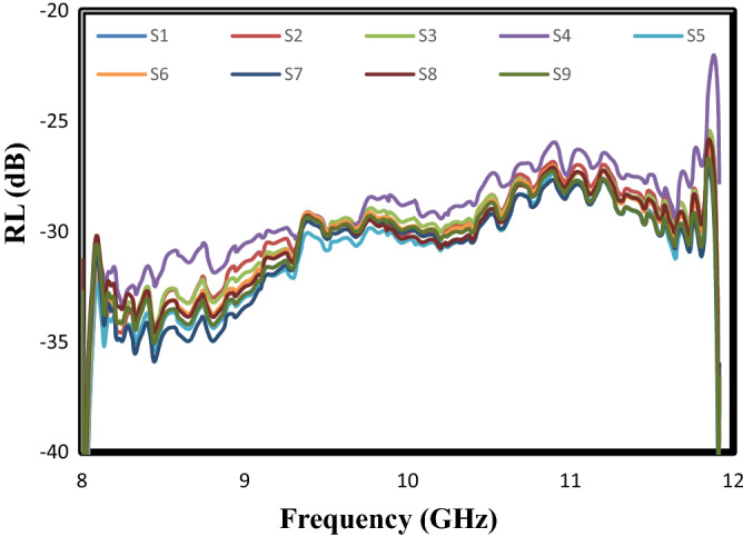
The frequency dependent of the reflection loss (RL) curves of sample prepared based on the Taguchi method; According to Tables 1 and 2, S1: experiment 1, S2: experiment 2, S3: experiment 3, S4: experiment 4, S5: experiment 5, S6: experiment 6, S7: experiment 7, S8: experiment 8, S9: experiment 9.
Table 3.
The calculated values for the area under of the reflection loss (RL) curves by Qualitek-4 software.
| Test | Area under the curves (GHz dB) |
|---|---|
| 1 | 122.31 |
| 2 | 120.63 |
| 3 | 120.70 |
| 4 | 115.90 |
| 5 | 124.00 |
| 6 | 121.39 |
| 7 | 124.02 |
| 8 | 121.33 |
| 9 | 122.31 |
Table 4.
Analysis of variance (ANOVA).
| Parameter | DOF (f) | Sum of square (Sʹ) | Variance (v) | Percent (%) |
|---|---|---|---|---|
| 1 | 2 | 6.90 | 3.45 | 14.82 |
| 2 | 2 | 2.35 | 1.18 | 5.05 |
| 3 | 2 | 16.62 | 8.31 | 35.69 |
| 4 | 2 | 20.69 | 10.34 | 44.44 |
| Other/error | 0 | 0.00 | 0.00 | |
| Total | 8 | 100 |
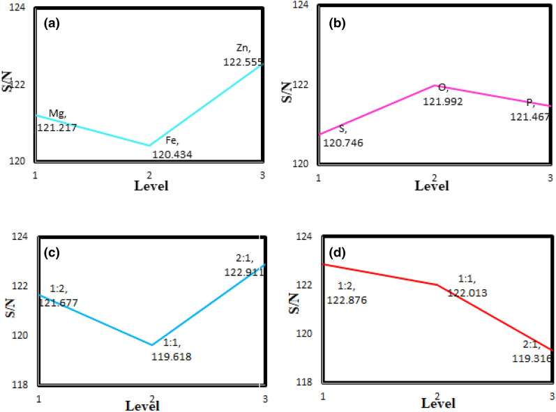
The effect of uncontrollable factors (noise) on the system response should be minimized to determine the optimal conditions in the Taguchi method. Figure 5a presents the influence levels for the type of dielectric material on the S/N ratio. According to this figure, the third level (i.e., ZnTiO3) has the most significate effect on the S/N ratio and reduces the reflection from the absorber surface. Figure 5b displays the S/N ratio results versus the levels of the type of dopant in g-C3N4. Based on the results obtained, oxygen as a dopant in g-C3N4 has the highest S/N ratio. As a result, it plays a significant role in improving the performance of the adsorbents. Figure 5c indicates the influence of the weight ratio of MTiO3:NiFe2O4 on the performance of microwave absorbents in the X-band. As can be observed, the highest S/N ratio is related to the 2:1 ratio of the dielectric material to the magnetic material. It shows that a high amount of dielectric filler compared to magnetic material leads to an increase in the number of the polarization domain. Figure 5d presents the impact of the total weight ratio of the magnetic and dielectric material to the conductive material on the S/N ratio, in which the 1:2 ratio has the most impact on the absorbent performance.
Figure 5.
Effect of the levels for (a) the type of dielectric material; (b) the type of dopant in g-C3N4; (c) the weight ratio of MTiO3:NiFe2O4; (d) the total weight ratio of MTiO3/NiFe2O4: X-doped g-C3N4.
Design of optimal nanocomposite
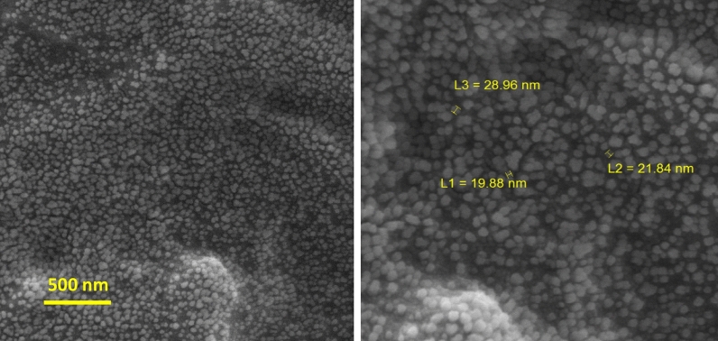
In the present work, the Taguchi experimental design was performed to optimize the nanocomposites’s formulation according to the maximum value of the area under the RL curve at X-band. Based on the results found from the ANOVA table, the optimum sample includes ZnTiO3, O-g-C3N4, NiFe2O4, the 2:1 weight ratio for MTiO3:NiFe2O4, and the 1:2 weight ratio for MTiO3/NiFe2O4: X-doped g-C3N4 (the most significate parameter). Figure 6 exhibits the surface morphology of the optimum sample, in which the nanofillers with particle sizes about 19–29 nm were well distributed in the polyester substrate. Figure 7 shows the frequency dependence of the RL curve for the optimum sample at 1 mm thickness. As can be seen, this nanocomposite has a reflectance loss (RL) of less than − 30 dB, equivalent to 99.9% absorption, and broad bandwidth. Moreover, the area under the RL curve for the optimal nanocomposite was calculated 125.38 dB, which confirms the value predicted by the experimental design software (126.19 dB) with a slight difference. More importantly, Table 5 displays the microwave absorption properties of some synthesized absorbers over several recent years. Strong absorption combined with wide bandwidth and a thin thickness made the optimal nanocomposite a highly competitive absorbent. Therefore, the ZnTiO3, O-g-C3N4, NiFe2O4, and polyester nanocomposite in this work was promising as a microwave absorbing material.
Figure 6.
SEM images of the absorber prepared under the optimal conditions.
Figure 7.
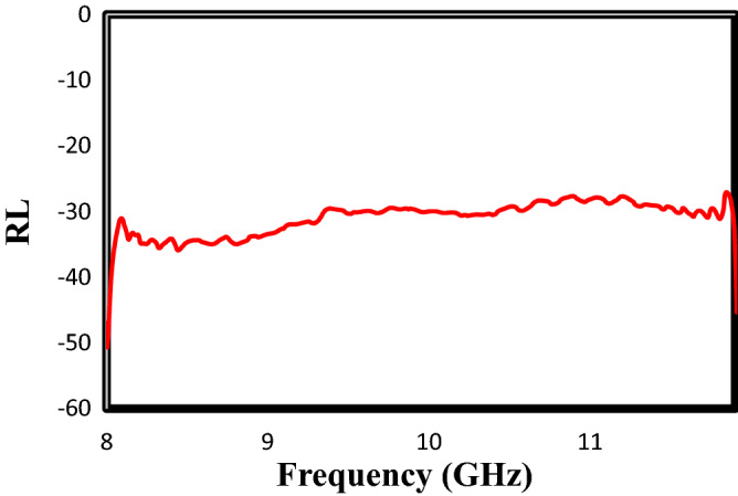
The frequency dependent of reflection loss (RL) curves for the absorber prepared under the optimal conditions at X-band.
Table 5.
The microwave absorption performance of some reported absorbents over several recent years.
| Nanocomposite | Optimal RL value (dB) | Frequency of Maximum RL (GHz) | Bandwidth (GHz) RL < − 10 dB | Thickness (mm) | Frequency range (GHz) | References |
|---|---|---|---|---|---|---|
| CoFe2O4 nanoparticles-decorated Ti3C2 MXene | − 30.9 | 13.9 | 8.5 | 1.5 | 8.3–16.8 | 13 |
| Copper-cobalt–nickel ferrite/graphene oxide/polyaniline | − 33.0 | 10.8 | – | 2.0 | 2–18 | 7 |
| MnFe9n+3O15n+4(0 ≤ n ≤ 1) (M = Ba, Sr)/CaCu3Ti4O12/phosphorus-doped g-C3N4 | − 30.0 | X-band | 4.0 | 1.0 | 8–12 | 16 |
| (Ba0.5Sr0.5Fe12O19)0.6/(NiFe2O4)0.4 | − 38.7 | 8.26 | – | 2.5 | 8–12 | 14 |
| g-C3N4 and polyester | − 10.0 | X-band | 4.0 | 2.0 | 8–12 | 6 |
| SrTiO3/SrFe12O19/ polyaniline | − 15.0 | 9.2 | 1.6 | 1.0 | 8–12 | 40 |
| La doped barium titanate | − 41.0 | 9.8 | 1.7 | 2.0 | 8–12 | 41 |
| ZnTiO3, O-g-C3N4, NiFe2O4, and polyester | − 30.0 | X-band | 4.0 | 1 | 8–12 | This work |
The ,, and Γ were calculated using the direct method of the Nicholson–Ross–Weir (NRW) algorithm and the scattering parameters. According to NRW, The reflection coefficient (Γ) can be calculated as follows:
| 5 |
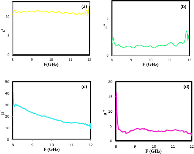
where S11 and S21 are the reflected and transmitted signals obtained by the vector network analyzer, respectively42. The plots of the complex electric permittivity () and the complex magnetic permeability () versus the frequency can be used to determine the microwave absorption mechanism by the prepared absorbent in the optimal conditions. For this purpose, the real parts of the complex expressions (i.e., and ) are attributed to the energy storage in the absorbers, and the imaginary parts (i.e., and ) are related to the energy loss and its conversion to heat by absorbers. Figure 8a,b displays the variations of the real () and imaginary () parts of the complex electric permittivity for the optimal sample in the X-band frequency range. According to these figures, the and are independent of the frequency variation, which shows the dielectric constant of ZnTiO3 as the dielectric material is free from the used frequency range. Figure 8c,d shows the frequency dependence of and for the prepared sample under the optimum conditions. As shown in Fig. 8c, the values decrease with a gentle slope from 35 to 10 as the frequency increases. It is ascribed to the high conductivity of O-g-C3N4 and thereby increasing the interfacial and dipolar polarization. According to Fig. 8d, no change in the values is observed with the changing frequency from 8 to 12 GHz.
Figure 8.
The relative complex permeability (a) real part () and (b) imaginary part (); the relative complex permittivity (c) real part () and (d) imaginary part () at X-band for optimum sample.
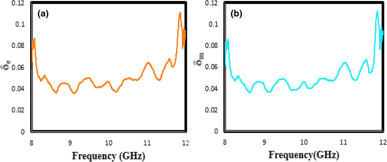
Dielectric loss tangent (tan (δe) = /) and magnetic loss tangent (tan (δm) = /) can be used to better investigate the microwave absorption characteristics in optimum nanocomposite. In other words, as the magnetic and dielectric loss tangents increases, the microwave absorber efficiency increases. According to Fig. 9a,b, both tan (δm) and tan (δe) for the optimal sample are dominated in the range of 0.06–0.1, which should benefit to achieve good impedance matching.
Figure 9.
The tangent curves of (a) the electrical permeability (δe) (b) the magnetic permittivity (δm) versus frequency indicated to optimal sample.
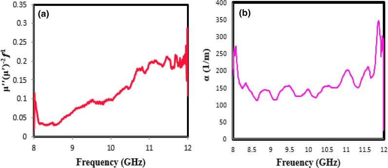
Factors influencing magnetic loss in a magnetic material include eddy current effect, domain-wall resonance, hysteresis loss, and natural resonance. The hysteresis loss is due to the irreversible magnet, which occurs in a highly functional field and can be omitted at a high frequency and reduced applied field. The domain-wall resonance from multi-domain materials usually appears in the range of 100–100 MHz. Besides, if the ()−2f1 value remains constant with frequency-changing, the magnetic loss is due to the eddy current loss43. The values of ()−2f1 vary significantly with increasing frequency, as shown in Fig. 10a. As a result, the magnetic loss for the prepared sample under the optimal condition is due to natural resonance.
Figure 10.
The values of (a) ()−2f1; (b) attenuation constant (α) versus frequency for optimal sample.
Another important factor to better understand the behavior of microwave absorbents is the use of attenuation constant (), which can be expressed as the following equation:
| 6 |
According to Eq. (6), the attenuation constant depends on the two parameters of dielectric loss and magnetic loss; increasing the last two parameters leads to further attenuation of the microwave waves or increasing the attenuation constant44,45. Figure 10b shows the plot of attenuation constant () versus frequency range from 8 to 12 GHz for the optimum sample. As shown in this figure, the synthesized sample has further (more than 200 dB/m) at the frequency range (X-band), which confirms the severe attenuation of the microwave in the absorber.
Conclusions
In summary, a novel microwave-absorber polyester coating containing the nanofillers of NiFe2O4, X-doped g-C3N4 (M = S, P, and O), and MTiO3 (M = Fe, Mg, and Zn) was successfully designed. Based on the results obtained from the Taguchi method, the optimum conditions for the synthesis of a great microwave absorbent included: ZnTiO3, O-g-C3N4, NiFe2O4, the 2:1 weight ratio for MTiO3:NiFe2O4, and the 1:2 weight ratio for MTiO3/NiFe2O4: X-doped g-C3N4. The optimal sample has reflection loss (RL) values less than − 30 dB at a high-frequency range (8–12 GHz) with a thickness of 1 mm. It was found that the combination of the conductor, magnetic, and dielectric materials leads to good impedance matching and increasing dipolar polarization. Moreover, the high values of magnetic loss tangent, dielectric loss tangent, and attenuation constant demonstrated the ability of the prepared coatings for the absorption and the conversion of electromagnetic energy into heat at X-band. Thus, the optimal nanocomposite proposed in this study can be used as a promising absorber with low density and thickness.
Supplementary Information
Acknowledgements
The authors would like to thank the University of Zanjan for financial and other supports.
Author contributions
S.S.: Investigation. M.S.S.D.: Supervision, Project administration, Methodology, Writing—review and editing. S.F.H.: Formal analysis, Writing—original draft. M.H.R.: Supervision. I.H.: Investigation, Methodology. A.A.-G.: Formal analysis.
Competing interests
The authors declare no competing interests.
Footnotes
Publisher's note
Springer Nature remains neutral with regard to jurisdictional claims in published maps and institutional affiliations.
Supplementary Information
The online version contains supplementary material available at 10.1038/s41598-021-98666-6.
References
- 1.Zhou C, Wang X, Luo H, Deng L, Wang S, Wei S, Zheng Y, Jia Q, Liu J. Interfacial design of sandwich-like CoFe@ Ti3C2Tx composites as high efficient microwave absorption materials. Appl. Surf. Sci. 2019;494:540–550. doi: 10.1016/j.apsusc.2019.07.208. [DOI] [Google Scholar]
- 2.Song Q, Ye F, Yin X, Li W, Li H, Liu Y, Li K, Xie K, Li X, Fu Q. Carbon nanotube–multilayered graphene edge plane core–shell hybrid foams for ultrahigh-performance electromagnetic-interference shielding. Adv. Mat. 2017;29:1701583. doi: 10.1002/adma.201701583. [DOI] [PubMed] [Google Scholar]
- 3.Cao W-T, Chen F-F, Zhu Y-J, Zhang Y-G, Jiang Y-Y, Ma M-G, Chen F. Binary strengthening and toughening of MXene/cellulose nanofiber composite paper with nacre-inspired structure and superior electromagnetic interference shielding properties. ACS Nano. 2018;12:4583–4593. doi: 10.1021/acsnano.8b00997. [DOI] [PubMed] [Google Scholar]
- 4.Liu Y, Chen Z, Zhang Y, Feng R, Chen X, Xiong C, Dong L. Broadband and lightweight microwave absorber constructed by in situ growth of hierarchical CoFe2O4/reduced graphene oxide porous nanocomposites. ACS Appl. Mater. Interfaces. 2018;10:13860–13868. doi: 10.1021/acsami.8b02137. [DOI] [PubMed] [Google Scholar]
- 5.Wang L, Yu X, Li X, Zhang J, Wang M, Che R. MOF-derived yolk-shell Ni@ C@ ZnO Schottky contact structure for enhanced microwave absorption. Chem. Eng. J. 2020;383:123099. doi: 10.1016/j.cej.2019.123099. [DOI] [Google Scholar]
- 6.Sareshkeh AT, Dorraji MSS, Rasoulifard MH. The role of g-C3N4 as nanofiller in improvement of mechanical, thermal, and X-band wave absorption properties of epoxy vinyl ester coating. Prog. Org. Coat. 2018;125:472–480. doi: 10.1016/j.porgcoat.2018.10.002. [DOI] [Google Scholar]
- 7.Sun J, Wang L, Yang Q, Shen Y, Zhang X. Preparation of copper-cobalt-nickel ferrite/graphene oxide/polyaniline composite and its applications in microwave absorption coating. Prog. Org. Coat. 2020;141:105552. doi: 10.1016/j.porgcoat.2020.105552. [DOI] [Google Scholar]
- 8.Xu X, Wang G, Wan G, Shi S, Hao C, Tang Y, Wang G. Magnetic Ni/graphene connected with conductive carbon nano-onions or nanotubes by atomic layer deposition for lightweight and low-frequency microwave absorption. Chem. Eng. J. 2020;382:122980. doi: 10.1016/j.cej.2019.122980. [DOI] [Google Scholar]
- 9.Agarwal K, Prasad M, Katiyar M, Jaiswal R, Kumar S, Prasad NE. Study of electromagnetic properties of fabricated NiFe2O4/polyurethane nanocomposites. J. Appl. Polym. Sci. 2020;137:48645. doi: 10.1002/app.48645. [DOI] [Google Scholar]
- 10.Açıkalın E, Atıcı O, Sayıntı A, Çoban K, Erkalfa H. Preparation of dendritic waterborne polyurethane-urea/Ni–Zn ferrite composite coatings and investigation of their microwave absorption properties. Prog. Org. Coat. 2013;76:972–978. doi: 10.1016/j.porgcoat.2012.10.008. [DOI] [Google Scholar]
- 11.Qu Y, Yang H, Yang N, Fan Y, Zhu H, Zou G. The effect of reaction temperature on the particle size, structure and magnetic properties of coprecipitated CoFe2O4 nanoparticles. Mater. Lett. 2006;60:3548–3552. doi: 10.1016/j.matlet.2006.03.055. [DOI] [Google Scholar]
- 12.Fabrèges X, Ressouche E, Duc F, de Brion S, Amara M, Detlefs C, Paolasini L, Suard E, Regnault L-P, Canals B. Field-driven magnetostructural transitions in GeCo2O4. Phys. Rev. B. 2017;95:014428. doi: 10.1103/PhysRevB.95.014428. [DOI] [Google Scholar]
- 13.He J, Liu S, Deng L, Shan D, Cao C, Luo H, Yan S. Tunable electromagnetic and enhanced microwave absorption properties in CoFe2O4 decorated Ti3C2 MXene composites. Appl. Surf. Sci. 2020;504:144210. doi: 10.1016/j.apsusc.2019.144210. [DOI] [Google Scholar]
- 14.Mathews SA, Babu DR, Saravanan P, Hayakawa Y. Microwave absorption studies of (Ba0.5Sr0.5Fe12O19)1–x/(NiFe2O4)x hard/soft ferrite nanocomposite. Mater. Chem. Phys. 2020;252:123063. doi: 10.1016/j.matchemphys.2020.123063. [DOI] [Google Scholar]
- 15.Kumar A, Singh AK, Tomar M, Gupta V, Kumar P, Singh K. Electromagnetic interference shielding performance of lightweight NiFe2O4/rGO nanocomposite in X-band frequency range. Ceram. Int. 2020;46:15473–15481. doi: 10.1016/j.ceramint.2020.03.092. [DOI] [Google Scholar]
- 16.Kadkhodayan H, Dorraji MS, Rasoulifard M, Amani-Ghadim A, Hajimiri I, Sareshkeh AT. Enhanced microwave absorption property of MnFe9n+3O15n+4 (0≤n≤1) (M = Ba, Sr)/CaCu3Ti4O12/phosphorus-doped g-C3N4 nanocomposite: Preparation and optimization. J. Alloys Compd. 2018;735:2497–2506. doi: 10.1016/j.jallcom.2017.12.017. [DOI] [Google Scholar]
- 17.Li Q, Yin X, Duan W, Kong L, Hao B, Ye F. Electrical, dielectric and microwave-absorption properties of polymer derived SiC ceramics in X band. J. Alloys Compd. 2013;565:66–72. doi: 10.1016/j.jallcom.2013.02.176. [DOI] [Google Scholar]
- 18.Yu J, Chi F, Sun Y, Guo J, Liu X. Assembled porous Fe3O4@ g-C3N4 hybrid nanocomposites with multiple interface polarization for stable microwave absorption. Ceram. Int. 2018;44:19207–19216. doi: 10.1016/j.ceramint.2018.07.143. [DOI] [Google Scholar]
- 19.Zhang X-J, Wang G-S, Cao W-Q, Wei Y-Z, Liang J-F, Guo L, Cao M-S. Enhanced microwave absorption property of reduced graphene oxide (RGO)-MnFe2O4 nanocomposites and polyvinylidene fluoride. ACS Appl. Mater. Interfaces. 2014;6:7471–7478. doi: 10.1021/am500862g. [DOI] [PubMed] [Google Scholar]
- 20.Feng W, Wang Y, Chen J, Wang L, Guo L, Ouyang J, Jia D, Zhou Y. Reduced graphene oxide decorated with in-situ growing ZnO nanocrystals: Facile synthesis and enhanced microwave absorption properties. Carbon. 2016;108:52–60. doi: 10.1016/j.carbon.2016.06.084. [DOI] [Google Scholar]
- 21.Wang H, Meng F, Huang F, Jing C, Li Y, Wei W, Zhou Z. Interface modulating CNTs@ PANi hybrids by controlled unzipping of the walls of CNTs to achieve tunable high-performance microwave absorption. ACS Appl. Mater. Interfaces. 2019;11:12142–12153. doi: 10.1021/acsami.9b01122. [DOI] [PubMed] [Google Scholar]
- 22.Hu Q, Yang R, Mo Z, Lu D, Yang L, He Z, Zhu H, Tang Z, Gui X. Nitrogen-doped and Fe-filled CNTs/NiCo2O4 porous sponge with tunable microwave absorption performance. Carbon. 2019;153:737–744. doi: 10.1016/j.carbon.2019.07.077. [DOI] [Google Scholar]
- 23.Lei S, Fan H, Ren X, Fang J, Ma L, Liu Z. Novel sintering and band gap engineering of ZnTiO3 ceramics with excellent microwave dielectric properties. J. Mater. Chem. C. 2017;5:4040–4047. doi: 10.1039/C7TC00815E. [DOI] [Google Scholar]
- 24.Ru J, Hua Y, Xu C, Li J, Li Y, Wang D, Gong K, Wang R, Zhou Z. Microwave-assisted preparation of submicron-sized FeTiO3 powders. Ceram. Int. 2014;40:6799–6805. doi: 10.1016/j.ceramint.2013.11.142. [DOI] [Google Scholar]
- 25.Rai U, Singh L, Mandal K, Singh N. An overview on recent developments in the synthesis, characterization and properties of high dielectric constant calcium copper titanate nano-particles. Nanosci. Technol. 2014;1:1–17. [Google Scholar]
- 26.Hu S, Zhou Y, He M, Liao Q, Yang H, Li H, Xu R, Ding Q. Hollow Ni-Co layered double hydroxides-derived NiCo-alloy@ g-C3N4 microtubule with high-performance microwave absorption. Mater. Lett. 2018;231:171–174. doi: 10.1016/j.matlet.2018.08.048. [DOI] [Google Scholar]
- 27.Peymanfar R, Karimi J, Fallahi R. Novel, promising, and broadband microwave-absorbing nanocomposite based on the graphite-like carbon nitride/CuS. J. Appl. Polym. Sci. 2020;137:48430. doi: 10.1002/app.48430. [DOI] [Google Scholar]
- 28.Nosrati H, Mamoory RS, Le DQS, Bünger CE. Enhanced fracture toughness of three dimensional graphene-hydroxyapatite nanocomposites by employing the Taguchi method. Compos. Part B Eng. 2020;190:107928. doi: 10.1016/j.compositesb.2020.107928. [DOI] [Google Scholar]
- 29.Ayhan V, Çangal Ç, Cesur İ, Çoban A, Ergen G, Çay Y, Kolip A, Özsert İ. Optimization of the factors affecting performance and emissions in a diesel engine using biodiesel and EGR with Taguchi method. Fuel. 2020;261:116371. doi: 10.1016/j.fuel.2019.116371. [DOI] [Google Scholar]
- 30.Manohar A, Krishnamoorthi C. Structural, optical, dielectric and magnetic properties of CaFe2O4 nanocrystals prepared by solvothermal reflux method. J. Alloys Compd. 2017;722:818–827. doi: 10.1016/j.jallcom.2017.06.145. [DOI] [Google Scholar]
- 31.Parsian P, Dorraji MS, Hosseini S, Rasoulifard M, Hajimiri I, Amani-Ghadim A. Facile preparation of an enhanced microwave absorbing based on polyester composite containing Ca3Al2Si3O12, polyaniline, and spinel ferrite (Cu, Mg, and Ni) nanoparticles. Mater. Chem. Phys. 2020;255:123529. doi: 10.1016/j.matchemphys.2020.123529. [DOI] [Google Scholar]
- 32.Fang LJ, Wang XL, Zhao JJ, Li YH, Wang YL, Du XL, He ZF, Zeng HD, Yang HG. One-step fabrication of porous oxygen-doped gC3N4 with feeble nitrogen vacancies for enhanced photocatalytic performance. Chem. Commun. 2016;52:14408–14411. doi: 10.1039/C6CC08187H. [DOI] [PubMed] [Google Scholar]
- 33.Wang K, Li Q, Liu B, Cheng B, Ho W, Yu J. Sulfur-doped g-C3N4 with enhanced photocatalytic CO2-reduction performance. Appl. Catal. B Environ. 2015;176:44–52. [Google Scholar]
- 34.Fang HB, Zhang XH, Wu J, Li N, Zheng YZ, Tao X. Fragmented phosphorus-doped graphitic carbon nitride nanoflakes with broad sub-bandgap absorption for highly efficient visible-light photocatalytic hydrogen evolution. Appl. Catal. B Environ. 2018;225:397–405. doi: 10.1016/j.apcatb.2017.11.080. [DOI] [Google Scholar]
- 35.Yu X, Lin G, Zhang D, He H. An optimizing method for design of microwave absorbing materials. Mater. Des. 2006;27:700–705. doi: 10.1016/j.matdes.2004.12.022. [DOI] [Google Scholar]
- 36.Xu J, Liu J, Che R, Liang C, Cao M, Li Y, Liu Z. Polarization enhancement of microwave absorption by increasing aspect ratio of ellipsoidal nanorattles with Fe3O4 cores and hierarchical CuSiO3 shells. Nanoscale. 2014;6:5782–5790. doi: 10.1039/C4NR00158C. [DOI] [PubMed] [Google Scholar]
- 37.Singh L, Rai U, Mandal K, Rai AK. Effect of processing routes on microstructure, electrical and dielectric behavior of Mg-doped CaCu3Ti4O12 electro-ceramic. Appl. Phys. A. 2013;112:891–900. doi: 10.1007/s00339-012-7443-z. [DOI] [Google Scholar]
- 38.Li Z-Q, Wang H-L, Zi L-Y, Zhang J-J, Zhang Y-S. Preparation and photocatalytic performance of magnetic TiO2–Fe3O4/graphene (RGO) composites under VIS-light irradiation. Ceram. Int. 2015;41:10634–10643. doi: 10.1016/j.ceramint.2015.04.163. [DOI] [Google Scholar]
- 39.Xu Y, Yuan L, Cai J, Zhang D. Smart absorbing property of composites with MWCNTs and carbonyl iron as the filler. J. Magn. Magn. Mater. 2013;343:239–244. doi: 10.1016/j.jmmm.2013.04.051. [DOI] [Google Scholar]
- 40.Hosseini SH, Zamani P, Mousavi SY. Thermal infrared and microwave absorbing properties of SrTiO3/SrFe12O19/polyaniline nanocomposites. J. Alloys Compd. 2015;644:423–429. doi: 10.1016/j.jallcom.2015.05.099. [DOI] [Google Scholar]
- 41.Liu Y, Feng Y, Wu X, Han X. Microwave absorption properties of La doped barium titanate in X-band. J. Alloys Compd. 2009;472:441–445. doi: 10.1016/j.jallcom.2008.04.081. [DOI] [Google Scholar]
- 42.Dorraji MS, Rasoulifard M, Khodabandeloo M, Rastgouy-Houjaghan M, Zarajabad HK. Microwave absorption properties of polyaniline-Fe3O4/ZnO-polyester nanocomposite: Preparation and optimization. Appl. Surf. Sci. 2016;366:210–218. doi: 10.1016/j.apsusc.2016.01.102. [DOI] [Google Scholar]
- 43.Wei H, Yin X, Jiang F, Hou Z, Cheng L, Zhang L. Optimized design of high-temperature microwave absorption properties of CNTs/Sc2Si2O7 ceramics. J. Alloys Compd. 2020;823:153864. doi: 10.1016/j.jallcom.2020.153864. [DOI] [Google Scholar]
- 44.Quan L, Qin F, Li Y, Estevez D, Fu G, Wang H, Peng H. Magnetic graphene enabled tunable microwave absorber via thermal control. Nanotechnology. 2018;29:245706. doi: 10.1088/1361-6528/aabaae. [DOI] [PubMed] [Google Scholar]
- 45.Yan F, Zong Y, Zhao C, Tan G, Sun Y, Li X, Ren Z, Zheng X. Porous Co nanospheres supported on nitrogen-doped graphene as high-efficiency electromagnetic wave absorbers with thin thickness. J. Alloys Compd. 2018;742:928–936. doi: 10.1016/j.jallcom.2018.01.388. [DOI] [Google Scholar]
Associated Data
This section collects any data citations, data availability statements, or supplementary materials included in this article.


