Abstract
Injuries to the extremities often require resection of necrotic hard tissue. For large-bone defects, autogenous bone grafting is ideal but, similar to all grafting procedures, is subject to limitations. Synthetic biomaterial-driven engineered healing offers an alternative approach. This work focuses on three-dimensional (3D) printing technology of solid-free form fabrication, more specifically robocasting/direct write. The research hypothesizes that a bioactive calcium-phosphate scaffold may successfully regenerate extensive bony defects in vivo and that newly regenerated bone will demonstrate mechanical properties similar to native bone as healing time elapses. Robocasting technology was used in designing and printing customizable scaffolds, composed of 100% beta tri-calcium phosphate (β-TCP), which were used to repair critical sized long-bone defects. Following full thickness segmental defects (~11 mm × full thickness) in the radial diaphysis in New Zealand white rabbits, a custom 3D-printed, 100% β-TCP, scaffold was implanted or left empty (negative control) and allowed to heal over 8, 12, and 24 weeks. Scaffolds and bone, en bloc, were subjected to micro-CT and histological analysis for quantification of bone, scaffold and soft tissue expressed as a function of volume percentage. Additionally, biomechanical testing at two different regions, (a) bone in the scaffold and (b) in native radial bone (control), was conducted to assess the newly regenerated bone for reduced elastic modulus (Er) and hardness (H) using nanoindentation. Histological analysis showed no signs of any adverse immune response while revealing progressive remodelling of bone within the scaffold along with gradual decrease in 3D-scaffold volume over time. Micro-CT images indicated directional bone ingrowth, with an increase in bone formation over time. Reduced elastic modulus (Er) data for the newly regenerated bone presented statistically homogenous values analogous to native bone at the three time points, whereas hardness (H) values were equivalent to the native radial bone only at 24 weeks. The negative control samples showed limited healing at 8 weeks. Custom engineered β-TCP scaffolds are biocompatible, resorbable, and can directionally regenerate and remodel bone in a segmental long-bone defect in a rabbit model. Custom designs and fabrication of β-TCP scaffolds for use in other bone defect models warrant further investigation.
Keywords: 3D printing, bioactive ceramic, calcium phosphate, in vivo, regeneration, scaffolds
1 |. INTRODUCTION
Approximately 500,000 bone-defect repairs, either requiring bone grafts or complex reconstruction modalities, are performed in the United States at a cost of $2.5 billion annually (Ong & Guda, 2016). In general, fractures, and/or bony defects, can only heal in environments conducive to osteogenesis and over short distances. At the outset of fracture healing, a weak osteogenic interface forms between newly forming and original bone, permitting bone remodelling through coupled osteoblastic and osteoclastic activity. This innate mechanism is, unfortunately, often inadequate in settings that require significant bony and soft tissue regeneration such as extensive trauma, oncologic resection, or chronic osteomyelitis. Such Scenarios may result in large defects—segments of bone loss that will not heal through endogenous healing mechanisms. These defects are reconstructive challenges due to the large amounts of hard (and often soft) tissue that need to be replaced in order to restore both form and function.
When treating such lesions in the upper extremity, one of the current solutions is tissue transfer from the contralateral arm, as this can provide resurfacing of arm fat and skin, but, unfortunately, this method can only provide small bony segments (Reigstad, Hetland, Bye, et al., 1992). An autologous fibula graft may be used for larger defects (Malizos et al., 2010) but comes at the cost of donor-site morbidity, longer operating times, and significant hospital costs (Hidalgo, 1994; Hidalgo & Rekow, 1995; Hultman, 2016). Allograft from cadaveric donors is another option that may be utilized; however, this modality may cause an immune response, has the potential for disease transmission, and may not be a viable option for a patient with certain religious beliefs (Nather, Yusof, & Hilmy, 2010). Additionally, there is evidence that allograft is not as effective as an autograft in healing bony defects in extremities (Kuremsky, Schaller, Hall, Roehr, & Masonis, 2010). These limitations have been the impetus for advancements in synthetic biomaterials (alloplasts) and tissue engineering for bone regeneration.
Alloplastics are biomaterials synthesized to function as tissue substitutes, with advantages including unlimited quantity and the avoidance of surgical harvest site complications (Moore, Graves, & Bain, 2001; Witek, Smay, Silva, et al., 2013). However, despite decades of use, biomaterials still do not adequately address large, complex bony defect repair. These repair sites require an interaction between the synthetic grafting material and the defect margin, which is not adequate with granular-based grafting materials, as they cannot be properly shaped to fit and fill the defect in a geometrically stable fashion. In addition, though osseoconductive, granular-based graft materials provide nucleation sites for osteogenesis in a random fashion; this lack of spatial coordination hinders organized directional bone growth and subsequent remodelling necessary for complete repair (Sweet et al., 2015). Such a mechanism is often satisfactory in small dental and craniofacial defects, as these may be multiple-wall defects that facilitate particulate material packing. However, in long bones, the lack of structural stability of particulate graft further hinders directional growth, adding to potential non-union (Mastrogiacomo et al., 2005; Moore et al., 2001). Furthermore, developments in additive manufacturing, such as three-dimensional (3D) printing, may allow biomaterials to overcome such limitations by allowing the construction of a patient specific, customizable, geometrically stable, load bearing, osseoconductive, synthetic graft.
The 3D printing technique of solid free-form fabrication, more specifically direct-write (DW) technology, has been adapted for the production of tissue regenerative bioactive ceramics (Hutmacher, 2000; Ricci, Clark, Murriky, & Smay, 2012). DW printing, which deposits concentrated colloidal gels, “ink,” controlled by computer-aided design (CAD)/computer-aided manufacturing system (Sun & Lal, 2002), allows for fabrication of constructs without the need for a mold (Miranda, Saiz, Gryn, & Tomsia, 2006). The controlled extrusion of colloidal pastes, slurries, or inks can “print” structures that are adapted from clinical imaging (e.g., CT scans), allowing for the printing of custom-fit and fill scaffolds with macrogeometric, mesogeometric, and microgeometric porous dimensions proven to be osseoconductive in other biomaterial studies (Ellingsen, Johansson, Wennerberg, et al., 2004; Lopez et al., 2017).
These 3D-printed bioactive ceramic (3DPBC)-based scaffolds, previously composed of hydroxyapatite (HA—[Ca10(PO4)6(OH)2]-based designs, have been well described in the literature with an in vivo resorption rate ~2%/year 5-year postimplantation (Moore, Graves, & Bain, 2001). This unresolved issue of protracted HA degradation led to the investigation of other materials for the regeneration of bone. The bioactive ceramic β-tricalcium phosphate (β-TCP-[Ca3(PO4)2] has demonstrated, both in vitro and in vivo, to have a more rapid resorption rate than HA while maintaining osseoconductive properties. This should, in theory, be advantageous for facilitating bone replacement during healing (Witek, Smay, Silva, et al., 2011).
There is a paucity of investigations assessing the regenerative capacity of 3D-printed bioceramics designed with osseoconductive geometries in vivo. Although the principles of these devices have begun to report promising outcomes, most of these studies have been in either non-load bearing skeletal models or small animal models with limited translational applications. (Bose, Tarafder, & Bandyopadhyay, 2016; Temple, Hutton, Hung, et al., 2014; Zhang et al., 2014b). The objective of this study was to assess 3DPBC scaffolds, composed of β-TCP, for the regeneration of critical size long-bone defects in an in vivo translational, load-bearing rabbit radius model. We hypothesized that a 3D-printed, lattice-based porous ceramic scaffold can be osseoconductive and will facilitate bone remodelling until normal bone morphology and mechanical properties are achieved.
2 |. MATERIALS AND METHODS
2.1 |. Scaffold material processing, characterization, design, and assembly
2.1.1 |. Materials processing and colloidal gel preparation
Commercially available beta tri-calcium phosphate (β-TCP; Product 21218, Lot 1305078, Sigma-Aldrich, Germany) Ca3(PO4)2 was used as the ceramic material in this study. The raw, as-received powder was calcined in an alumina crucible at 800°C for 11 hr. After cooling, the powder was attrition milled (1-mm zirconia milling media, Union Process, Akron, OH) in distilled water (DI—H2O) for 30 min (Model L001 Attritor System, Union Process, Akron, OH). The water-ceramic suspension was then separated from the milling media. The ceramic slurry was placed in a low-temperature oven (~80°C) for approximately 8 hr to allow the water to separate/evaporate, leaving the dried solid material. The resulting solid material was then transferred into a Nalgene bottle (Witek et al., 2013) charged with ~25 pieces of zirconia milling media (10-mm diameter), which was then agitated for ~15 min in a paint shaker (1400 Classic Shaker, Red Devil Equipment Company, Plymouth, MN).
The calcined and milled β-TCP was then used for the colloidal gel formulation. Concentrated β-TCP suspension for the scaffolds, where volume fraction (ϕceramics) of ceramic was ϕceramics = 0.42 to 0.5, was produced by mixing a precalculated amount of ceramic powder and ammonium polyacrylate dispersant (Darvan 821A®; RT Vanderbilt, Norwalk, CT) to stabilize the ceramic particles in DI—H2O. Darvan 821A is a 40% aqueous solution of ammonium polyacrylate. The dispersant proportion per gram of ceramics was ~15 mg (Szpalski, Nguyen, Vasiliu, et al., 2012; Witek et al., 2013). First, ~25 g of milling media was added to the DI—H2O, then the dispersant, and then the ceramic powder in three parts (33.3%/step). After each addition of powder, the suspension was mixed in the planetary mixer (Thinky AR-250; Thinky, Tokyo, Japan) for 1 min. Next, hydroxypropylmethylcellulose, also referred to as F4M, (Methocel F4M; Dow Chemical Company, Midland, MI) was added as the viscosifying agent. The F4M was used in a 5% by weight aqueous solution with a proportion of 7 mg/ml of liquid phase. The suspension was then mixed for 1 min, followed by a defoaming step for 1 min in the planetary mixer. Finally, the suspension was gelled by adding ~150 mg per 30 ml of ink of polyethyleneimine (Sigma-Aldrich, St. Louis, MO) 10% by weight solution. Mixing and defoaming (1 min and 30 s, respectively) after the final addition completed the ink preparation procedure.
2.1.2 |. Design and assembly
The β-TCP scaffolds were fabricated, utilizing a 3D DW microprinter gantry robot system to extrude the colloidal ink (Aerotech Inc. Pittsburgh, PA; Figure 1; Silva, Witek, Coelho, et al., 2010; Simon, Michna, Lewis, et al., 2007; Smay, Cesarano III, & Lewis, 2002). The 3D long-bone-shaped scaffolds (10.5-mm length, 4.5-mm Doutside, 2.25-mm Dinside, 330-μm struts, and approximately 400-μm pore spacing; Figure 2a–c) were designed utilizing a CAD, RoboCAD 4.3 (3D Inks LLC, Tulsa, OK). To produce a well-rounded structure, the software calculated a necessary support structure composed of a fugitive ink support (Figure 2b–f) material, an aqueous paste composed of carbon black particles, which was co-deposited along with the colloidal ink as previously described (Silva et al., 2010).
FIGURE 1.
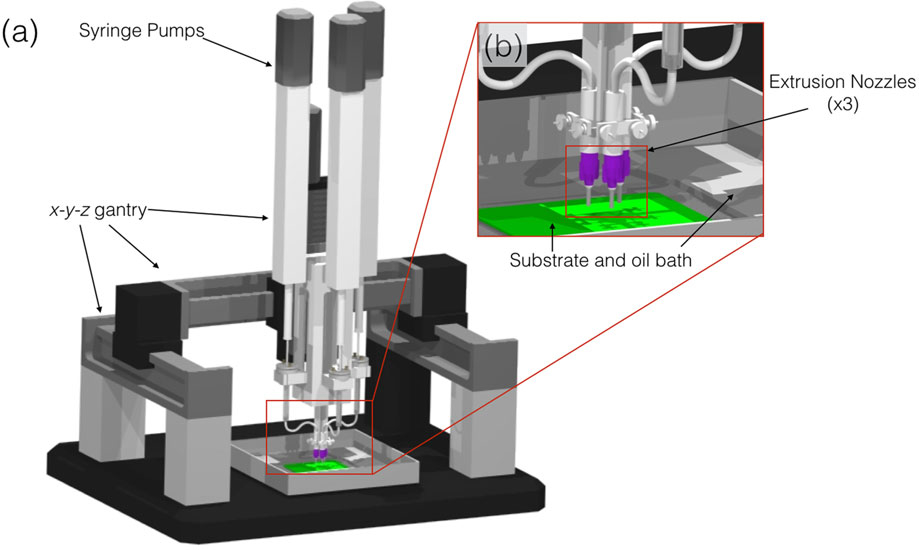
Schematic of robocasting machine (3D Inks LLC, Tulsa, OK) used to assemble scaffolds. (a) Overall set-up of machine and (b) magnified set-up of extrusion nozzles (×3) capable of co-depositing multiple materials
FIGURE 2.

(a) Schematic of extrusion nozzle depositing filaments of material on a layer-by-layer basis and (b and c) Robocad 4.3 rendition of the designed long-bone scaffold, image shows front and side, respectively, respective measurements and indicates the fugitive support structure (Doutside = 4.85 mm, Dinside = 2.35, and length = 10.5 mm). Also, the intermittent computer-aided design layers of the structure are shown to better illustrate the build process, (d) Layer 0, (e) Layer 8, and (f) Layer 21. β-TCP: beta tricalcium phosphate
The previously prepared colloidal gel and support material were separately loaded into two individual 3-ml syringes (EFD Inc., Nordson, Westlake, OH) and subsequently equipped with 330-μm-diameter extrusion nozzle (EFD Inc., Nordson, Westlake, OH). The 3D cylindrical-shaped scaffolds were printed in a layer-by-layer fashion at 8 mm/s, utilizing a two-material system; upon completion of a specific layer, the gantry was translated up (z-axis) of a predefined distance, which was approximately 81% of the diameter of the extrusion nozzle, Figure 2d–f. The entire deposition process occurred in a low-viscosity paraffin oil tray to prevent drying of the structure during fabrication (Smay et al., 2002; Szpalski et al., 2012). After the scaffold was complete, it was removed from the oil reservoir and allowed to partially dry, before being sintered to 400°C for 2 hr; 900°C for 2 hr; and 1,100°C for 4 hrs, the dwell time at the two lower temperatures allowed for the burnout of the fugitive support material and organic components (Ricci et al., 2012; Simon et al., 2007; Szpalski et al., 2012). The scaffold itself undergoes densification during the high-temperature sintering process (Witek, Smay, Silva, et al., 2013), which involves shrinking, roughly 10% linear, yielding a structure with final dimensions of approximately 10-mm length, approximately 4.3-mm Doutside, 2.00-mm Dinside, and approximately 330-μm struts, Figure 2.
2.1.3 |. Density and porosity measurements
The density and porosity of the experimental ceramic material were characterized using helium pycnometry (Accupyc 1340, Norcross, GA) to measure the true solid volume of β-TCP rod samples (Vsolid) by averaging across 10 independent measures per specimen (n = 10). The length and diameter of each sample were determined by averaging three independent measurements to calculate the volume of the bounding cylinder (Vcylinder). This allowed computation of porosity as the void volume fraction as previously reported (Guda, Walker, Singleton, et al., 2012; Witek et al., 2013).
2.1.4 |. Scanning electron microscopy
A scanning electron microscope (SEM; S-3500N, Hitachi) was used to observe the sections of individual scaffolds, green state, and postsintering to 1,100°C, which comprise the scaffold. Two scaffolds were mounted onto a small stub and grounded with Graphite Conductive Adhesive 154 (Electron Microscopy Sciences, Fort Washington, PA). The stubs along with the attached section of rods were sputter coated (Denton Vacuum—Desk V, Moorestown, NJ) with a thin gold coating. Scanning electron micrographs were acquired under various magnifications and accelerating voltages.
2.1.5 |. Mechanical testing of fabricated scaffolds
The scaffolds were subjected to 3-point bending test for flexural stress analysis using a universal testing machine (Instron Series 5560, Norwood, MA; n = 10) equipped with a 50N load cell and the extension rate of 1 mm/min, set to load to failure. The flexural stress (σ) for cylindrical rods was calculated from
| (1) |
where P is the compressive load; D is the specimen diameter; and L0 is the span of lower supports (Witek et al., 2013).
Additionally, the scaffolds were also referred to compressive testing using a diametral compression testing method (n = 10) on a universal testing machine equipped with a 50N load cell and the compression rate of 1 mm/min. Tensile stress was approximated utilizing the formula
| (2) |
where P is the compressive load; D is the specimen diameter; and l is the specimen length (Fell & Newton, 1970; Witek et al., 2013).
2.1.6 |. Powder characterization: X-ray diffraction
The X-ray diffraction (XRD; Bruker AXS D8 Discover, Madison, WI) was used to determine the crystalline phases present within the raw material and sintered scaffold. Three different spectra from each testing group were obtained (n = 3 per group). The diffractometer, using a curved crystal monochromator, operated at 45 mA and 45 kV and scanned in the 2θ with a range from 20° to 65° (Witek et al., 2013), with a step size of 0.02° at 3 s per step.
Rietveld refinement analysis was applied to XRD spectra to give an approximate Ca/P ratio using the following equation:
| (3) |
The raw data were then input into Material Analysis Using Diffraction software for quantitative analysis. Rietveld analysis utilized the samples from previous XRD spectra (i.e., peak, heights, widths, and positions). This refinement method was used to quantify the percentage of each phase (HA, β-TCP, and other commonly observed phases in calcium- and phosphate-based materials such as calcium oxide) present in different calcination temperatures and sintering groups. A least-square fit approach was utilized to measured scans until replicating a theoretical scan (based on the structure in Inorganic Crystal Structure Database) (Rietveld, 1993; Taylor & Hinczak, 2006). The background, cell parameters, preferred orientation; peak asymmetry, atomic positions, site occupancy factors, and global vibrational parameters were refined. The calculated and observed patterns were plotted by least-squares method until a minimum was reached. Five iterations were utilized, and the integrated intensities and the peaks heights were related to a scale factor. The fraction of each phase was determined by
| (4) |
where Wi is the weight fraction of the phase, S is the scale factor, Z is the number of formulas per unit cell, M is the mass of the formula unit, V the unit cell volume, and i and j are the phase under analysis and j all phases in the system (Coelho et al., 2009; Witek et al., 2013).
2.1.7 |. Differential scanning calorimetry and thermogravimetric analysis
To analyse burnout behaviour as a function of sintering temperature, while simultaneously removing water and organic phases, approximately 40 mg of colloidal gel was loaded into a Al2O3 crucible (using a matching cover with a central hole; AdValue Technology, Tucson, AZ) and characterized utilizing a differential scanning calorimeter (DSC)/thermogravimetric analyzer (TGA; STA 449 F1 Jupiter®, Burlington, MA). The heating profile from 40°C to 1,250°C was carried out with a ramp rate of 2.5°C/min in zero hydrocarbon air (ZHCAir, Airgas USA, Radnor, PA) composed of 80/20 N2/O2 ratio (at a flow rate of 150 ml/min), to mimic the conditions of sintering.
2.2 |. Animal model and surgical procedure
The study examined 100% β-TCP scaffolds at three time points (8, 12, and 24 weeks) in vivo. A total of 14 skeletally mature New Zealand white rabbits, weighing ~3.5 kg, were used for the approximately 11-mm segmental radius full-thickness defect surgical procedure (described below). Nine rabbits were analysed at 8 weeks (four negative control-defect with no scaffold/graft and five experimental-defect filled with scaffold). Three experimental group rabbits were analysed at 12 weeks and another three at 24 weeks; the 12- and 24-week time points did not have negative controls.
All surgeries were performed using sterile surgical techniques, and scaffolds were sterilized via gamma irradiation (Gamma 1000) at a dose of 25 kGY, following approval of Institutional Animal Care and Use Committee. Preoperatively, buprenorphine (0.02 mg/kg) and enrofloxacin (5 mg/kg) were administered subcutaneously. Rabbits were anaesthetized via intramuscular administration of Ketamine (35 mg/kg) and Xylazine (5 mg/kg). A 3-cm incision was made, and an approximately 11-mm-size critical size defect was created on the radius; periosteum was resected to at least 1.5-cm proximal and distal to the defect, with each rabbit receiving one β-TCP scaffold. Four rabbits (n = 4) received no scaffold and served as the negative control. After scaffold placement, surgical hardware was utilized to hold the construct in place, followed by closure with overlying soft tissue and then skin closure.
Buprenorphine (0.01 mg/kg) and enrofloxacin (5 mg/kg) were administered subcutaneously every 12 hr for up to 48 hr post-op. Animals were given food, ad libitum, without any restrictions to their activity. At the end of their designated time point, the animals were euthanized via anaesthetic overdose.
2.3 |. Scaffold micro-CT analysis: Ex vivo
Upon termination of the experiment, the radius and the ulna were disarticulated from the humerus and removed en bloc. Excess soft tissue and bone were removed from proximal and distal regions of the surgical site. Samples were then dehydrated in a series of alcohol solutions ranging from 70% to 100% ethanol. The samples were then embedded in a methacrylate-based resin. Embedded samples were then scanned using microcomputed tomography (micro-CT 40, Scanco Medical, Basserdorf, Germany) with a slice resolution of 18 μm. Micro-CT slices were imaged at an X-ray energy level of 70 kVp, and a current of 114 μA and integration time was 150 ms. Data were exported in DICOM format and imported into Amira 6.1 software (Visage Imaging GmbH, Berlin, Germany) for evaluation. Amira software extracted volumetric and densitometric numbers from the grey value distribution of the 3D reconstructed images: The total bone volume, 3DPBC scaffold, and soft tissue/empty space were quantified from the defect site. This method allows for 3D quantitative analysis without destruction to the excised sample, which occurs during serial histological sectioning.
2.4 |. Histology
After scanning, the embedded blocks were cut into thin (~250 μm) sections using a low-speed diamond saw (Isomet 2000, Buehler Ltd., Lake Bluff, IL). The sections were glued onto acrylic slides and ground on a grinding machine (Metaserv 3000, Buehler, Lake Bluff, IL) under water irrigation with a series of SiC abrasive paper until they were ~100 μm thick, after which samples were stained in Stevenel’s blue and Van Gieson picro fuchsin (Maniatopoulos, Rodriguez, Deporter, et al., 1986). Stevenel’s blue stains cells and extracelluar structures in a subtle gradation of blue tones. The counterstain, Van Gieson’s picro-fuchsin, stains collagen fibers green or green-blue; bone, orange or purple; osteoid, yellow-green; and muscle fibers, blue to blue-green. This particular type of stain permitted for the differentiation between the soft, connective, osteoid, and mineralized tissues. It should be noted that the potential variation in stain is not a function of mineralization.
2.5 |. Nanoindentation testing
A second set of slides, processed in a similar manner as the histology slides to ~100 μm, with a sequential 9- to 1-μm monocrystalline diamond suspension (Buehler, Lake Bluff, IL) utilized for scratch removal with a final 0.05-μm polishing suspension surface finish. The nanoindentation testing (n = 10 per specimen) was performed using a nanoindenter (Hysitron TI 950, Minneapolis, MN) equipped with a Berkovich diamond three-sided pyramid probe (Baldassarri, Bonfante, Suzuki, et al., 2012). A previously developed loading profile with a peak of 300 μN at a rate of 60 μN/s, followed by a holding time of 10 s and an unloading time of 2 s, was used (Figure 3a), producing a load–displacement curve (Figure 3b; Baldassarri et al., 2012).
FIGURE 3.
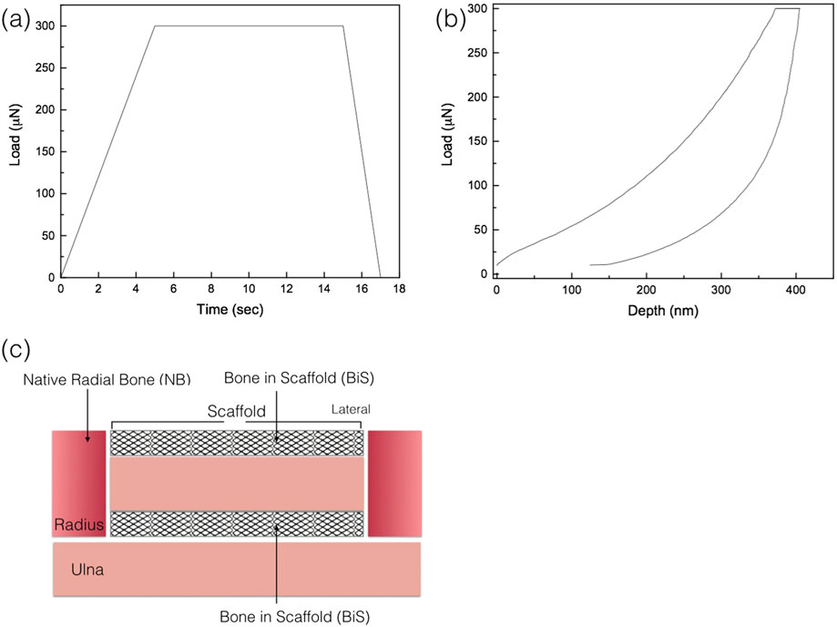
(a) Load as function of time, quasistatic testing profile; (b) a representative load displacement graph of the nanoindentation analysis; and (c) schematic representation of areas where nanoindentation was performed: native radial bone (NB) and bone in scaffold (BiS)
For specimens at each experimental time point (8, 12, and 24 weeks in vivo), nanoindentation testing was performed in two regions: (a) newly formed bone between remaining graft struts in the scaffold (BiS) and (b) native bone of the radius (Figure 3c). Each samples’ regions were assessed for the presence or absence of bone; nanoindentaion was only conducted in regions with bone present. A total of n = 10 indentations, separated by 10 μm from one another, were performed in each region at room temperature. Rehydration of the slides was performed by storing each specimen in nanopure water (18.2 MΩ; Millipore, USA) at room temperature for 1 hr prior to the test. Immediately before the test, nanopure water droplets were added for testing under wet environmental conditions (Doerner & Nix, 1986; Lee et al., 2013). Previous studies have illustrated that nanoindentation of bone should be performed in a wet environment, as the hydrated tissues show a pronounced viscoelastic behaviour with the higher loading rates significantly altering the interaction of collagen/water and the water flow, leading to higher mechanical properties (Kulin, Jiang, & Vecchio, 2008; Ntim, Bembey, Ferguson, et al., 2006).
From each analysed load–displacement curve (Figure 3b), reduced elastic modulus, Er, (GPa) and hardness, H, (GPa) of bone tissue were computed via the Hysitron TriboScan Software with the following formulas, respectively:
| (5) |
| (6) |
where S is the stiffness, hc is the contact depth, Pmax is the maximum force (300 μN) and A (hc) is the contact area computed from the Hysitron TriboScan software taking into account the area function with respect to contact depth (Oliver & Pharr, 1992b). From the reduced modulus, Er, the reduced elastic modulus of the bone (Eb) was calculated using the following relationship derived from Hertzian contact mechanics:
| (7) |
where vb is the Poisson’s ratio of the bone and Ei and vi are the elastic modulus and Poisson’s ratio of the indenter, respectively (Hoffler, Guo, Zysset, et al., 2005; Lee et al., 2013; Oliver & Pharr, 1992a). After nanoindentation was completed, slides were imaged under light microscopy (Zeiss Axiolmager M1 m, Carl Zeiss Microscopy, Thornwood, NY) and scanning electron microscopy (SEM) for verification of indents for samples.
2.6 |. Statistical analysis
Evaluation of porosity, bone mechanical properties, and reconstructed image data is presented as mean values with the corresponding 95% confidence interval values (mean ± 95% CI). 3D image quantification (percent bone, scaffold, and soft tissue/empty space) and nanoindentation data were analysed using a general linear mixed model approach with fixed factors of time in vivo (8, 12, and 24 weeks). All data were assessed for normality using the Shapiro–Wilk test prior to any analysis (IBM SPSS v23, IBM Corp., Armonk, NY). Values for bone, scaffold and soft tissue/empty space percentages were normalized and analysed by ANOVA with significance level (α) set at 0.05.
3 |. RESULTS
3.1 |. Material characterization
3.1.1 |. Density and porosity
The theoretical density of the ceramic used for ink formulations (i.e., 100% β-TCP) is 3.07 g/cm3, whereas the mean density (±95%CI) measurement by He pycnometry yielded to ~3.12 g/cm3 ± 0.01. With the sintered scaffold having an average porosity (±95% CI) of 58.6% ± 3.0, which was significantly lower (p = 0.035) in comparison with its green state counterpart with porosity of 63.4% ± 3.0.
3.1.2 |. Scanning electron microscopy
The scanning electron micrographs obtained for the two states are presented with Figure 4a representative of green state and Figure 4 b representing the final scaffold post sintering to 1,100°C. Scanning electron microscopy showed smaller size particles for the green state (Figure 4a) and a decrease of porosity due to the fusion of the ceramic particles, as seen in Figure 4b, which occurs during sintering at 1,100°C for 4 hr.
FIGURE 4.
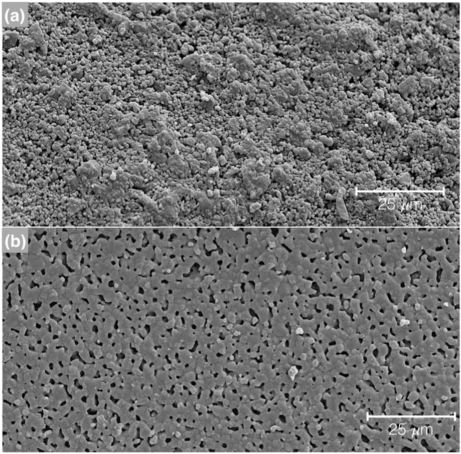
Scanning electron microscope (SEM) micrographs of the 100% β-TCP, (a) green state and (b) sintered to 1,100°C for 4 hr. The images were taken field emission SEM (Hitachi S-4800, Santa Clara, CA) at 15 kV
3.1.3 |. Mechanical property of scaffold
The tensile strength, obtained from the diametral compression test, for these porous scaffolds was calculated to be 14.76 ± 5N, provided information on the scaffold in bulk. The flexural strength result calculated from 3-point bending was 11.42 ± 8N, a substantially lower value In comparison to a solid cylindrical rod of β-TCP (67.6 ± 8N).
3.1.4 |. Powder characterization: XRD
XRD spectra were collected of the raw β-TCP material for crystalline verification and spectra matched the theoretical β-TCP (Figure 5a). After confirmation of the material was complete, and the experimental colloidal gels fabricated and subjected to sintering at 1100°C, XRD spectra obtained from the groups for crystalline phase determination and verification yielded three narrow and high-intensity peaks located at 27.9°, 31.2°, and 34.4° seen in the resultant spectra (Figure 5b).
FIGURE 5.
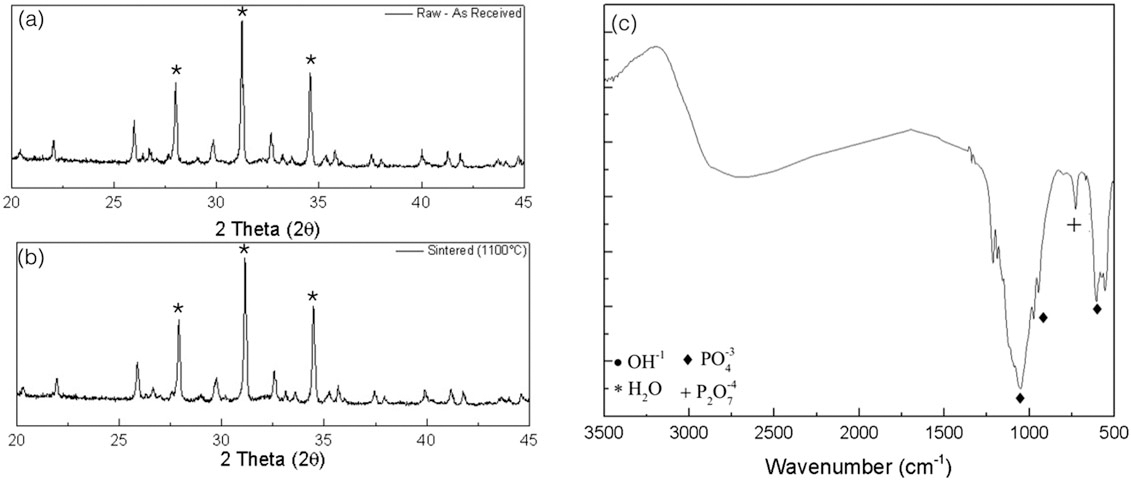
X-ray diffraction spectra for (a) the raw beta tricalcium phosphate (β-TCP) as received from the supplier and (b) represents the sintered to 1,100°C scaffold, with a few of the most intense diffraction peaks representative of β-TCP indicated with an (*). (c) Fourier-transform infrared spectroscopy spectra is shown for the sintered scaffold with few representative groups denoted with respective symbols
3.1.5 |. DSC, TGA, and Fourier-transform infrared spectroscopy
DSC results revealed two peaks, an endothermic peak at ~100°C (Figure 6a), indicative of water evaporating from the material. An exothermic peak at ~300°C is indicative of hydroxypropylmethylcellulose evaporation, the viscosyfing agent.
FIGURE 6.
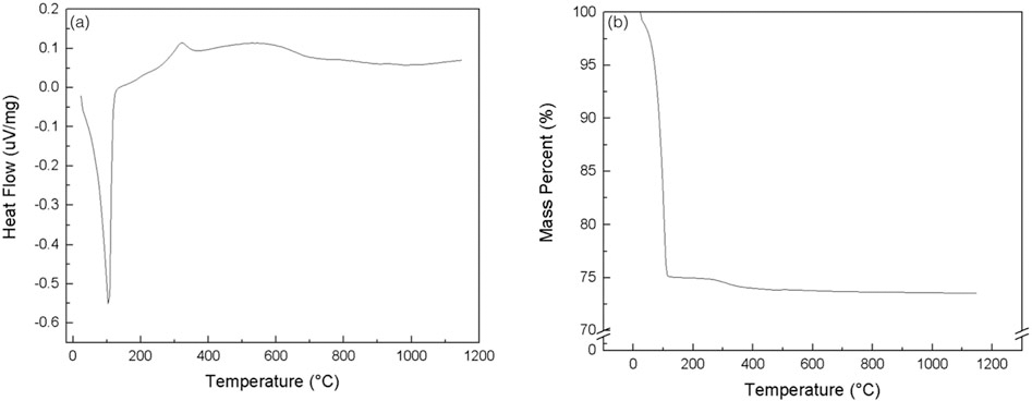
The figure represents the spectra from the (a) differential scanning calorimetry and (b) thermogravimetric analysis of the 100% beta tricalcium phosphate scaffold being subjected to a heating profile similar to that of the sintering profile
TGA results of green state colloidal gel are shown in Figure 6b. There was a rapid decrease in overall mass percent (%) at ~100°C, due to water evaporation, Darvan 821A® dispersant, the F4M viscosifying agent, and polyethyleneimine. The calculated weight fraction of ceramic gels in dried form is wsolid = ~0.65. As seen in the spectra, the weight loss equilibriates around greater than ~150°C and remains constant to the ultimate sintering temperature of 1,100°C.
Fourier transform infrared spectroscopy spectra showed phosphate group (PO4) peaks at wave numbers from around 1,100 to 1,040 cm−1 as well as double peaks in the ~600 to the 560 cm−1 ranges, whereas peaks in the 850 to 600 cm−1 areas are indicative of the pyrophosphate group (P2O7; Figure 5c).
3.2 |. In vivo analysis
There were no signs of pain or swelling postsurgically. After sacrifice, the radii were extracted en bloc, and grossly, there were no indications of infection, independent of time point.
Samples from the three in vivo time points (8, 12, and 24 weeks) were analysed after being subject to μCT scanning and subsequent reconstruction via Amira software 6.1 (Visage Imaging GmbH, Berlin, Germany). 3D renderings (Figure 7a,b), cross-sectional micro-CT (Figure 7c), and histological micrograph (Figure 7d) of the negative control samples at 8 weeks in vivo showed no bridging, and defect gaps ranging 9–11 mm were observed. Reconstructed images of the experimental groups (with scaffold) are shown in Figure 8a–c, whereas 3D analysis values for bone, scaffold and soft tissue/empty space are shown in Figure 9 and listed in Table 1. Qualitative micro-CT data along with respective reconstructed images indicated directional bone ingrowth along the bone long axis, with an increase in bone formation toward the original bone morphology over time. Samples at 8 weeks (Figure 8a) illustrate extensive bone formation with early signs of scaffold resorption. At 12 weeks and subsequently 24 weeks, a substantially greater amount of bone was depicted leading to regeneration of the radii marrow space, as shown in Figure 8b,c, respectively. Further, at 24 weeks (Figure 8c), the scaffold has significantly resorbed, presenting extensive structural discontinuity.
FIGURE 7.
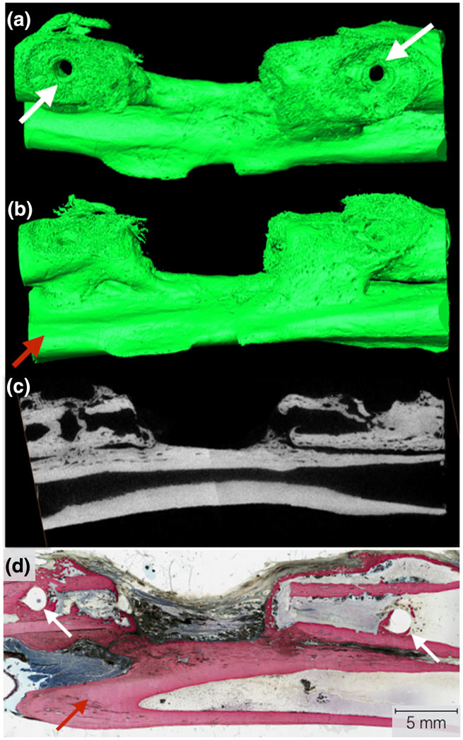
Three-dimensional Amira rendering of the negative control at 8 weeks. (a) Top view of the radius defect with visible bone plate screw holes (white arrows). The bone plate and screws were removed for viewing purposes; (b) lateral view of radial defect with the ulna visibly present (red arrow); (c) μCT cross-sectional slice representing a two-dimensional representation of the radius, radius defect, and ulna visible; and (d) representative histological cross section of the negative defect in the radius, with the white arrows indicating the screw locations for the surgical hardware
FIGURE 8.
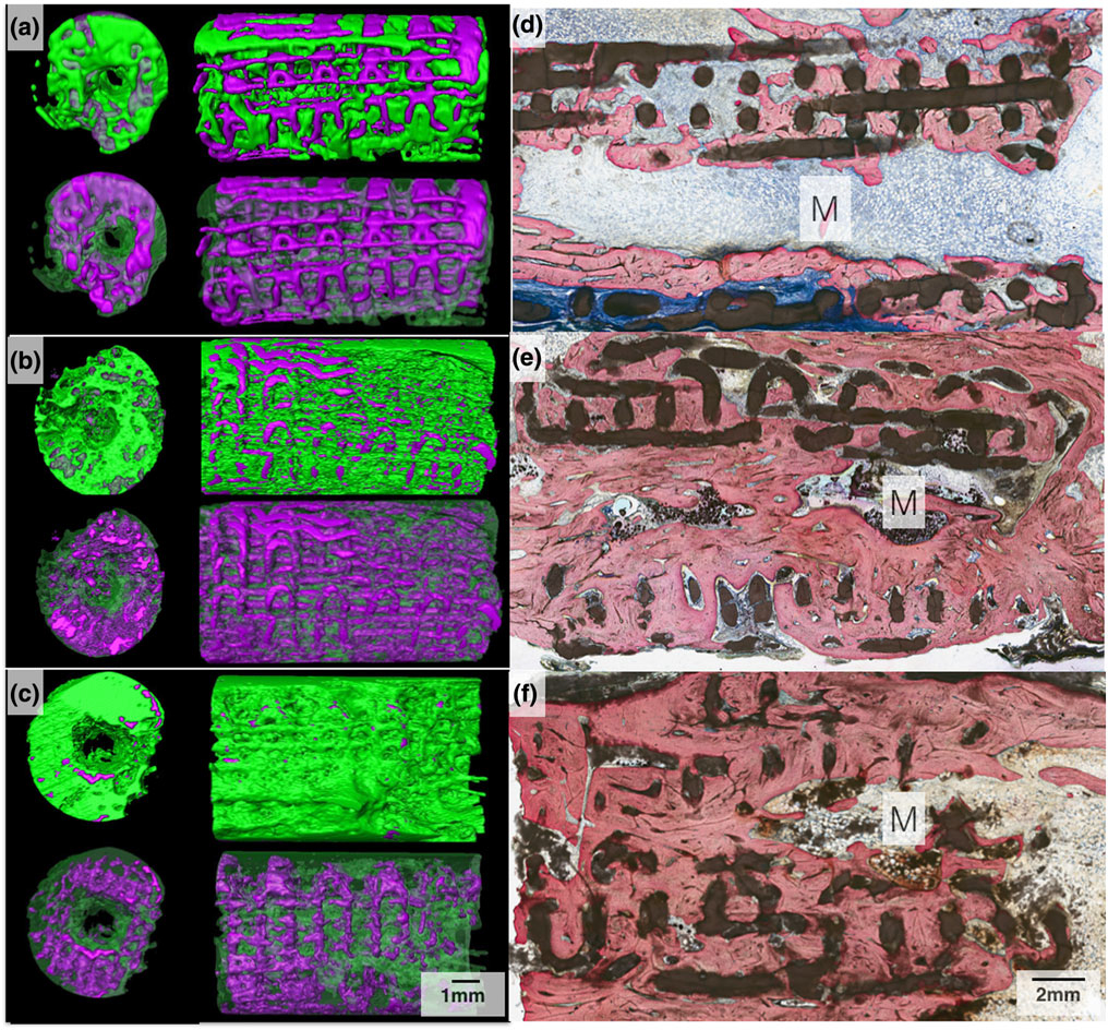
Three-dimensional Amira rendered representation of the radius samples with 3D-printed bioactive ceramic (3DPBC) scaffold (purple) and bone (green) at (a) 8 weeks, (b) 12 weeks, and (c) 24 weeks. Histological cross section of the radius defect along the long axis of the 3DPBC scaffold and defect site at (d) 8 weeks, (e) 12 weeks, and (f) 24 weeks. The marrow (M) space is visible with yellow marrow observed at 12- and 24-week time points. Stevenel’s blue and Van Gieson Picro Fuchsin stained
FIGURE 9.

Bone, scaffold, and soft tissue/empty space percentage analysis following μCT scanning and Amira software volumetric quantification. Mean and 95% confidence interval values for bone and scaffold percentage quantification. Letter case denote statistically homogenous groups for respective group (capital, scaffold; lower case, bone)
TABLE 1.
Mean and 95% confidence interval values for bone, scaffold, and soft tissue/empty space percentage quantification
| Time: in vivo | Bone | Scaffold | Soft Tissue |
|---|---|---|---|
|
| |||
| 8 Weeks | 30.34a (± 12.25) | 46.17B (± 10.9) | 23.49C (± 7.75) |
| 12 Weeks | 58.77A (± 15.81) | 28.77b (± 14.16) | 12.46c (± 10.01) |
| 24 Weeks | 61.79A (± 15.81) | 18.79b (± 14.16) | 19.42C,c (±10.01) |
Note. Letters denote statistically homogenous groups.
The quantitative bone regeneration and consequent scaffold degradation analysis indicated that there was a statistically significant greater amount of bone at 12- and 24 -week compared with 8-week samples (p = 0.011). Statistical analysis indicated significance between 8- and 12-week samples (p = 0.023) and between 8- and 24-week samples (p = 0.005; Figure 9). With regards to the remaining scaffold material, there were no statistical significance differences between 12- and 24-week samples (p = 0.384). Significantly greater amounts of scaffold material were detected for the 8-week samples relative to 12 and 24-week samples (p < 0.05; Figure 9).
3.2.1 |. Histology
Histologically, a tissue interface without an adverse inflammatory response was observed between the 3DPBC and the remodelling bone, at all time points, Figure 10. At 8 weeks, woven bone, osteoid formation, and osteocytes were found directly interfacing the individual bioactive ceramic struts (Figure 10a), with osteocytes, osteoblasts, and osteoclasts actively remodelling bone on the surface of the scaffold and within the scaffold’s porous network. Woven bone, composed of disorganized ossein, mineral content, and osteocytes (Figure 10b), was far more prevalent at 8 weeks than mature bone in the healing defect. Additionally, minor signs of primary osteon formation are present (Figure 10b).
FIGURE 10.
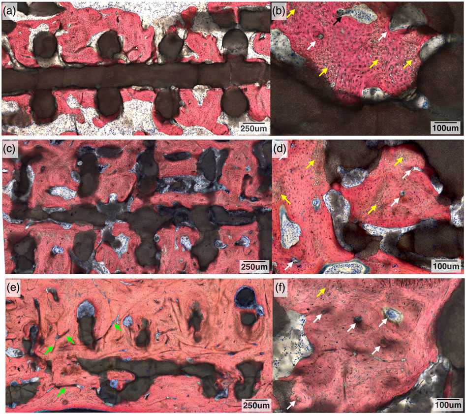
Histological cross section of the radius defect along the long axis of the three-dimensional-printed bioactive ceramic scaffold and defect site at 8 weeks: (a) low magnification and (b) high magnification. White arrows denote signs of primary osteon formation, and yellow arrows denote woven bone. At 12 weeks: (c) low magnification and (d) high magnification. White arrows denote signs of further osteon formation, and yellow arrows denote woven bone. At 24 weeks: (e) low magnification and (f) high magnification. Green arrows denote Haversian canals, white arrows denote signs of further osteon formation, and yellow arrows denote woven bone. Stevenel’s blue and Van Gieson Picro Fuchsin stained
At 12 weeks, an increase in the amount of mineralized tissue and organized ossein network is observed (Figure 10c) with mineralized bone displaying osteoblasts actively synthesizing osteoid. Osteon formation is more apparent with the initial development of a haversian network (Figure 10d). There was decreased woven bone (Figure 10d) at 12 weeks when compared with the 8-week samples. For the 24-week samples, the amount of bone and ossein/mineral organization was increased relative to the prior time points, with further remodelling leading to the development of an extensive haversian system (Figure 10e).
Degradation of the scaffold was observed, as the original circular cross-sectional strut geometry was altered, taking on an increasingly discontinuous and irregularly shaped form as time elapsed in vivo (Figures 8 and 10). No exuberant bone growth was apparent, as the remodelling bone was limited to the defect site and the 3DPBC scaffold geometry. The presence of a bone marrow canal was also observed (Figures 8e,f).
3.3 |. Nanoindentation
Nanoindentation points were visualized via an optical microscope image and SEM micrograph (Figure 11a,b, respectively). Analysis of the progressively healing/remodelling bone within the 3DPBC scaffold showed a reduced elastic modulus (ER) indicated lower values (mean ± 95% CI) for the 8- and 12-week samples, 9.9 ± 1.4 and 9.04 ± 1.4 GPa, respectively, compared with the 24-week samples, which had a mean of 12.6 ± 1.5 GPa. The mean ER for all three time points were statistically homogenous to that of the native radial bone (p = 0.11; Figure 12a). The resulting hardness (H) values did not have the same trend as the ER. Newly regenerated bone at 8 and 12 weeks had similar means, 0.320 ± 0.14 and 0.292 ± 0.14 GPa, respectively, whereas the values at 24 weeks, 0.468 ± 0.15 GPa, were statistically greater than the two previous time points (p = 0.03) and achieved statistical homogeneity values relative to native bone (Figure 12b).
FIGURE 11.
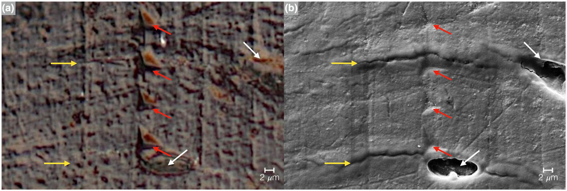
Imaging of the nanoindentation testing marks via (a) optical microscope image and (b) SEM micrograph. The red arrows indicate the indentation points, yellow arrows represent lamellae, and white arrows osteocyte lacunae
FIGURE 12.

Nanoindentation values of hydrated bone samples at 8, 12, and 24 weeks with native radius for comparison: (a) reduced elastic modulus (ER) of the three time points resulted in statistically homogenous to that of the native radial bone (p = 0.11); (b) hardness (H) of bone at 8 and 12 weeks had similar means, whereas the values at 24 weeks were statistically greater than the two previous time points and achieved statistical homogeneity values relative to native bone
4 |. DISCUSSION
Bone regeneration following a fracture is a complex biological process characterized by molecular events directing recruitment and growth of bone. Recent studies have suggested sources of signalling include local soft tissue, bone marrow, and systemic recruitment from circulation or satellite stem cell populations from muscle (Shah, Majeed, Jonason, & O’Keefe, 2013). Regardless, the natural scaffold of callus tissue and woven bone formed following a fracture acts as a spacer and is limited to the periphery of the fracture in critical sized defects, therefore not uniting the fracture ends (Chao, Aro, Lewallen, et al., 1989). Thus, osteoconductive bioactive scaffolds that can assist and guide bone growth would be ideal for total bone reconstruction and complete repair. This study focused on the healing of a large segmental defect in a rabbit radius utilizing a CAD-based custom 3DPBC scaffold and hypothesized that such an approach can restore form and function to the long bone defect.
The postsintering shrinkage values and corresponding porosity, caused by the fusion of β-TCP particles due to sintering, which were significantly different than the green state, correlate to values found in the literature (Witek et al., 2013). DSC and TGA testing indicated the evaporation of additives progressing from the green state to the final sintered scaffold, and the material characterization completed by FTIR and XRD with Rietveld refinement further verified the composition of the scaffold to be that of 100% β-TCP. Also, despite the 10% linear and 20% volumetric shrinkage due to sintering, the scaffold’s lattice-based pores of ~350 μm remained consistent. Upon evaluation of the 3-point bending values of the native rabbit radius (517 MPa ± 57N; Zhang et al., 2014a), our solid cylindrical β-TCP and lattice 3DPBC constructs achieved values 44% and 7.5%, respectively, in comparison. Due to this difference in values, a bone plate was surgically implanted to stabilize the scaffold within the radius defect. Such an approach resulted in no scaffold fracture throughout the study.
Qualitative and quantitative 3D volumetric and histologic analysis revealed that osteoconduction occurred throughout the entirety of the scaffold construct and respective defect and was not limited to the periphery of the healing bone, a common occurrence with critical-sized defects. Although progressive amounts of bone growth and remodelling were observed over the 8-, 12-, and 24-week time points, the largest proportion of woven bone was observed at 8 weeks, whereas at 12 and 24 weeks, an increase in the amount of osteons and the development of a Haversian system indicate the return toward the native bone form.
Along with bone osteogenesis, the degradation of the scaffold is evident over time with 3D analysis and with the histological differences seen in the geometry of the overall scaffold and its corresponding individual struts, both of which decreased in volume and diameter, resulting in a discontinuous structure. This absorption is likely to be a result of cellular resorption and dissolution by tissue fluids (Lu, Gallur, Flautre, et al., 1998; Zerbo, Bronckers, De Lange, et al., 2005) and allows for gradual mechanical loading to be transferred directly to the healing bone.
Previous studies have stated that pore sizes between ~100 and 300 μm have higher directional osseoconduction (Karageorgiou & Kaplan, 2005). The scaffold dimensions utilized in this study were larger than what has been previously reported for scaffold materials, as the design platform utilized for this study was based on previous metallic endosteal healing chamber studies (Coelho, Jimbo, Tovar, & Bonfante, 2015). Analogous to its metallic biomaterial counterpart, the histologic findings in this study suggest that the β-TCP scaffold lattice-based pores behaved as healing chambers that regenerated through an intramembranous-like healing pathway (Coelho & Jimbo, 2014). The scaffold in this study most likely further increased osteoconduction due to its bioactive composition and ionic release, therefore meeting the biological demands and facilitating the healing process of an extensive segmental defect in a long bone that, to the best of our knowledge, has not been achieved to date. The β-TCP scaffold structure, with macrometer and micrometer level porosity, allowed for its gradated degradation concomitantly with bone growth/remodelling. This permitted the biomechanical loading to the healing bone and may, in part, account for the rapid development of baseline bone mechanical properties (Er and H) in the regenerated tissue that, along with remodelling toward original bone morphology, is highly indicative of complete healing (Bose, Vahabzadeh, & Bandyopadhyay, 2013).
Nanoindentation verified the findings of the qualitative CT-based and histologic analyses that concluded that over time bone structure was reestablished with histomorphology consistent with mature cortical-like native bone. Nanoindentation showed quantitatively that the newly regenerated bone within the bioactive 3D printed scaffold achieved mechanical behaviour/properties comparable with the native uninvolved bone; this has not been demonstrated in previous studies. This demonstrates that the natural progression of bone healing was not compromised and the mechanical loads were progressively transferred across the span of the regenerating bone. The native uninvolved and regenerated bone samples showed no significant differences in reduced elastic modulus. Increases in hardness over time were observed, although in vivo no significant differences were found between the native hard tissue and hard tissue within the 3DPBC scaffold at the longest time point (24 weeks) evaluated. Considering that healing bone possesses a lower mineral content in comparison with mature bone, following secondary osteon formation (Dorlot, L’esperance, & Meunier, 1986; Rho, Roy, Tsui, & Pharr, 1999), our results indicate that the bone hardness at the later 24-week time approached structural properties of native bone.
Substantial variation in surgical techniques have been employed by different groups for the purpose of developing critically sized defects in the rabbit radius. Such surgical technique has resulted in a wide variation of critical defect length that may be attributed to variations on the degree of periosteal resection, segmental stabilization methods, among other variables (Hollinger & Kleinschmidt, 1990; Oryan, Bigham-Sadegh, & Abbasi-Teshnizi, 2014; Parizi, Oryan, Shafiei-Sarvestani, et al., 2013; Zhao, Huang, Zhang, et al., 2016). Although different studies indicate that approximately 11-mm-long defects may present partial healing or possibly segmental bridging over time, our negative control defects presented negligible bone healing relative to the defect size with the limited healing being restricted to the defect periphery. Such stunted regenerative capacity was likely due to the extensive periosteal resection performed (<1.5 cm from the defect margins) prior to rigid fixation installation. Due to the negligible healing presented at 8 weeks for the control group, its evolution toward complete healing reproducing the form and function of native bone observed at 12 and 24 weeks for the experimental group is highly unlikely.
5 |. CONCLUSION
Lattice-based porous custom engineered β-TCP scaffolds are biocompatible, resorbable, and can regenerate and remodel bone within the confines of the scaffold dimensions in a critical segmental long-bone defect in a rabbit model. Custom designs and fabrication of β-TCP scaffolds for use in other bone defect models warrant further investigation.
ACKNOWLEDGEMENTS
This work has been supported by Office of the Assistant Secretary of Defense for Health Affairs through the Reconstructive Transplant Research Program under Award No. W81XWH-16-1-0772 and NIH/NIAMS Grants AR068593 AR068593-02S, and AR068593-03S. The authors would also like to acknowledge Dr. James E. Smay (Department of Materials Science and Engineering, Oklahoma State University Tulsa, OK).
Funding information
National Institute of Arthritis and Musculoskeletal and Skin Diseases, Grant/Award Numbers: AR068593, AR068593-02S and AR068593-03S; U.S. Department of Defense, Grant/Award Number: W81XWH-16-1-0772
Footnotes
CONFLICTS OF INTEREST
The authors have declared that there is no conflict of interest.
REFERENCES
- Baldassarri M, Bonfante E, Suzuki M, et al. (2012). Mechanical properties of human bone surrounding plateau root form implants retrieved after 0.3–24 years of function. Journal of Biomedical Materials Research Part B: Applied Biomaterials, 100(7), 2015–2021. [DOI] [PubMed] [Google Scholar]
- Bose S, Tarafder S, & Bandyopadhyay A (2016). Effect of chemistry on osteogenesis and angiogenesis towards bone tissue engineering using 3D printed scaffolds. Annals of Biomedical Engineering, 1–12. [DOI] [PMC free article] [PubMed] [Google Scholar]
- Bose S, Vahabzadeh S, & Bandyopadhyay A (2013). Bone tissue engineering using 3D printing. Materials Today, 16(12), 496–504. [Google Scholar]
- Chao EY, Aro HT, Lewallen DG, et al. (1989). The effect of rigidity on fracture healing in external fixation. Clinical Orthopaedics and Related Research, 241, 24–35. [PubMed] [Google Scholar]
- Coelho PG, Coimbra ME, Ribeiro C, Fancio E, Higa O, Suzuki M, & Marincola M (2009). Physico/chemical characterization and preliminary human histology assessment of a β-TCP particulate material for bone augmentation. Materials Science and Engineering: C, 29(7), 2085–2091. [Google Scholar]
- Coelho PG, & Jimbo R (2014). Osseointegration of metallic devices: Current trends based on implant hardware design. Archives of Biochemistry and Biophysics, 561, 99–108. [DOI] [PubMed] [Google Scholar]
- Coelho PG, Jimbo R, Tovar N, & Bonfante EA (2015). Osseointegration: Hierarchical designing encompassing the macrometer, micrometer, and nanometer length scales. Dental Materials: Official Publication of the Academy of Dental Materials, 31(1), 37–52. [DOI] [PubMed] [Google Scholar]
- Doerner MF, & Nix WD (1986). A method for interpreting the data from depth-sensing indentation instruments. Journal of Materials Research, 1(04), 601–609. [Google Scholar]
- Dorlot J, L’esperance G, & Meunier A (1986). Characterization of single osteons: Microhardness and mineral content. Trans 32nd Orthop Res Soc, 11, 330. [Google Scholar]
- Ellingsen JE, Johansson CB, Wennerberg A, et al. (2004). Improved retention and bone-to-implant contact with fluoride-modified titanium implants. International Journal of Oral & Maxillofacial Implants, 19(5), 659–666. [PubMed] [Google Scholar]
- Fell J, & Newton J (1970). Determination of tablet strength by the diametral-compression test. Journal of Pharmaceutical Sciences, 59(5), 688–691. [DOI] [PubMed] [Google Scholar]
- Guda T, Walker JA, Singleton BM, et al. (2012). Guided bone regeneration in long-bone defects with a structural hydroxyapatite graft and collagen membrane. Tissue Engineering Part a, 19(17–18), 1879–1888. [DOI] [PMC free article] [PubMed] [Google Scholar]
- Hidalgo DA (1994). Condyle transplantation in free flap mandible reconstruction. Plastic and Reconstructive Surgery, 93(4), 770–781. [PubMed] [Google Scholar]
- Hidalgo DA, & Rekow A (1995). A review of 60 consecutive fibula free flap mandible reconstructions. Plastic and Reconstructive Surgery, 96(3), 585–596. [PubMed] [Google Scholar]
- Hoffler CE, Guo XE, Zysset PK, et al. (2005). An application of nanoindentation technique to measure bone tissue lamellae properties. Journal of Biomechanical Engineering, 127(7), 1046–1053. [DOI] [PubMed] [Google Scholar]
- Hollinger JO, & Kleinschmidt JC (1990). The critical size defect as an experimental model to test bone repair materials. Journal of Craniofacial Surgery, 1(1), 60–68. [DOI] [PubMed] [Google Scholar]
- Hultman CS (2016). Procedural portfolio planning in plastic surgery, Part 2: Collaboration between surgeons and hospital administrators to develop a funds flow model for procedures performed at an academic medical center. Annals of Plastic Surgery, 76, S347–S351. [DOI] [PubMed] [Google Scholar]
- Hutmacher DW (2000). Scaffolds in tissue engineering bone and cartilage. Biomaterials, 21(24), 2529–2543. [DOI] [PubMed] [Google Scholar]
- Karageorgiou V, & Kaplan D (2005). Porosity of 3D biomaterial scaffolds and osteogenesis. Biomaterials, 26(27), 5474–5491. [DOI] [PubMed] [Google Scholar]
- Kulin RM, Jiang F, & Vecchio KS (2008). Aging and loading rate effects on the mechanical behavior of equine bone. JOM, 60(6), 39–44. [Google Scholar]
- Kuremsky MA, Schaller TM, Hall CC, Roehr BA, & Masonis JL (2010). Comparison of autograft vs allograft in opening-wedge high tibial osteotomy. The Journal of Arthroplasty, 25, 951–957. [DOI] [PubMed] [Google Scholar]
- Lee KL, Sobieraj M, Baldassarri M, Gupta N, Pinisetty D, Janal MN, … Coelho PG (2013). The effects of loading conditions and specimen environment on the nanomechanical response of canine cortical bone. Materials science & engineering C, Materials for Biological Applications, 33(8), 4582–4586. [DOI] [PubMed] [Google Scholar]
- Lopez CD, Alifarag AM, Torroni A, Tovar N, Diaz-Siso JR, Witek L, … Coelho PG (2017). Osseodensification for enhancement of spinal surgical hardware fixation. Journal of the Mechanical Behavior of Biomedical Materials, 69, 275–281. [DOI] [PMC free article] [PubMed] [Google Scholar]
- Lu J, Gallur A, Flautre B, et al. (1998). Comparative study of tissue reactions to calcium phosphate ceramics among cancellous, cortical, and medullar bone sites in rabbits. Journal of Biomedical Materials Research, 42(3), 357–367. [DOI] [PubMed] [Google Scholar]
- Malizos KN, Dailiana ZH, Innocenti M, Mathoulin CL, Mattar R Jr., & Sauerbier M (2010). Vascularized bone grafts for upper limb reconstruction: defects at the distal radius, wrist, and hand. The Journal of Hand Surgery, 35(10), 1710–1718. [DOI] [PubMed] [Google Scholar]
- Maniatopoulos C, Rodriguez A, Deporter DA, et al. (1986). An improved method for preparing histological sections of metallic implants. The International Journal of Oral & Maxillofacial Implants, 1(1), 31–37. [PubMed] [Google Scholar]
- Mastrogiacomo M, Muraglia A, Komlev V, Peyrin F, Rustichelli F, Crovace A, & Cancedda R (2005). Tissue engineering of bone: Search for a better scaffold. Orthodontics & Craniofacial Research, 8(4), 277–284. [DOI] [PubMed] [Google Scholar]
- Miranda P, Saiz E, Gryn K, & Tomsia AP (2006). Sintering and robocasting of [beta]-tricalcium phosphate scaffolds for orthopaedic applications. Acta Biomaterialia, 2(4), 457–466. [DOI] [PubMed] [Google Scholar]
- Moore WR, Graves SE, & Bain GI (2001). Synthetic bone graft substitutes. ANZ Journal of Surgery, 71(6), 354–361. [PubMed] [Google Scholar]
- Nather A, Yusof N, & Hilmy N (2010). Allograft procurement, processing and transplantation: A comprehensive guide for tissue banks, world scientific. [Google Scholar]
- Ntim MM, Bembey AK, Ferguson VI, et al. (2006). Hydration Effects on the viscoelastic properties of collagen. MRS Proceedings, 898E(L05–02), 01–05. [Google Scholar]
- Oliver WC, & Pharr GM (1992a). An improved technique for determining hardness and elastic modulus using load and displacement sensing indentation experiments. Journal of Materials Research, 7(06), 1564–1583. [Google Scholar]
- Oliver WC, & Pharr GM (1992b). A method for interpreting the data from depth-sensing indentation instruments. Journal of Materials Research, 1, 601–609. [Google Scholar]
- Ong JL, & Guda T (2016). Translating biomaterials for bone graft: Benchtop to clinical applications. Boca Raton, FL: Crc Press. [Google Scholar]
- Oryan A, Bigham-Sadegh A, & Abbasi-Teshnizi F (2014). Effects of osteogenic medium on healing of the experimental critical bone defect in a rabbit model. Bone, 63, 53–60. [DOI] [PubMed] [Google Scholar]
- Parizi MA, Oryan A, Shafiei-Sarvestani Z, et al. (2013). Effectiveness of synthetic hydroxyapatite versus Persian Gulf coral in an animal model of long bone defect reconstruction. Journal of Orthopaedics and Traumatology, 14(4), 259–268. [DOI] [PMC free article] [PubMed] [Google Scholar]
- Reigstad A, Hetland KR, Bye K, et al. (1992). Free flaps in the reconstruction of hand and distal forearm injuries. The Journal of Hand Surgery, British VoIume, 1992, 17B, 185–188. [DOI] [PubMed] [Google Scholar]
- Rho JY, Roy ME, Tsui TY, & Pharr GM (1999). Elastic properties of microstructural components of human bone tissue as measured by nanoindentation. Journal of Biomedical Materials Research, 45(1), 48–54. [DOI] [PubMed] [Google Scholar]
- Ricci JL, Clark EA, Murriky A, & Smay JE (2012). Three-dimensional printing of bone repair and replacement materials: Impact on craniofacial surgery. Journal of Craniofacial Surgery, 23(1), 304–308. [DOI] [PubMed] [Google Scholar]
- Rietveld HM (1993). The Rietveld method. The early days: A retrospective view. ( pp. 39–42). Oxford, New York: The Rietveld Method Oxford University Press. [Google Scholar]
- Shah K, Majeed Z, Jonason J, & O’Keefe RJ (2013). The role of muscle in bone repair: The cells, signals, and tissue responses to injury. Current Osteoporosis Reports, 11(2), 130–135. [DOI] [PMC free article] [PubMed] [Google Scholar]
- Silva NRFA, Witek L, Coelho PG, et al. (2010). Additive CAD/CAM process for dental prostheses. Journal of Prosthodontics, 20(2), 93–96. [DOI] [PubMed] [Google Scholar]
- Simon JL, Michna S, Lewis JA, et al. (2007). In vivo bone response to 3D periodic hydroxyapatite scaffolds assembled by direct ink writing. Journal of Biomedical Materials Research Part a, 83(3), 747–758. [DOI] [PubMed] [Google Scholar]
- Smay JE, Cesarano J III, & Lewis JA (2002). Colloidal inks for directed assembly of 3-D periodic structures. Langmuir, 18(14), 5429–5437. [Google Scholar]
- Sun W, & Lal P (2002). Recent development on computer aided tissue engineering—A review. Computer Methods and Programs in Biomedicine, 67(2), 85–103. [DOI] [PubMed] [Google Scholar]
- Sweet L, Kang Y, Czisch C, Witek L, Shi Y, Smay J, … Yang Y (2015). Geometrical versus random β-TCP scaffolds: Exploring the effects on Schwann cell growth and behavior. PLoS One, 10(10), e0139820. [DOI] [PMC free article] [PubMed] [Google Scholar]
- Szpalski C, Nguyen PD, Vasiliu CEC, et al. (2012). Bony engineering using time-release porous scaffolds to provide sustained growth factor delivery. Journal of Craniofacial Surgery, 23(3), 638–644. [DOI] [PubMed] [Google Scholar]
- Taylor JC, & Hinczak I (2006). Rietveld made easy: A practical guide to the understanding of the method and successful phase quantifications, Sietronics Pty Limited. [Google Scholar]
- Temple JP, Hutton DL, Hung BP, et al. (2014). Engineering anatomically shaped vascularized bone grafts with hASCs and 3D-printed PCL scaffolds. Journal of Biomedical Materials Research Part a, 102(12), 4317–4325. [DOI] [PubMed] [Google Scholar]
- Witek L, Smay J, Silva N, et al. (2013). Sintering effects on chemical and physical properties of bioactive ceramics. Journal of Advanced Ceramics, 2(3), 227–284. [Google Scholar]
- Witek L, Smay J, Silva NRFA, et al. (2011). Sintering effects on the chemical and physical properties of bioactive ceramic rods biomaterials and biomimetics: New York University. [Google Scholar]
- Zerbo IR, Bronckers AL, De Lange G, et al. (2005). Localisation of osteogenic and osteoclastic cells in porous β-tricalcium phosphate particles used for human maxillary sinus floor elevation. Biomaterials, 26(12), 1445–1451. [DOI] [PubMed] [Google Scholar]
- Zhang M, Wang GL, Zhang HF, Hu XD, Shi XY, Li S, & Lin W (2014a). Repair of segmental long bone defect in a rabbit radius non-union model: Comparison of cylindrical porous titanium and hydroxyapatite scaffolds. Artificial Organs, 38(6), 493–502. [DOI] [PubMed] [Google Scholar]
- Zhang W, Lian Q, Li D, Wang K, Hao D, Bian W, … Jin Z (2014b). Cartilage repair and subchondral bone migration using 3D printing osteochondral composites: A one-year-period study in rabbit trochlea. BioMed Research International, 2014, 1–16. [DOI] [PMC free article] [PubMed] [Google Scholar]
- Zhao M-D, Huang J-S, Zhang X-C, et al. (2016). Construction of radial defect models in rabbits to determine the critical size defects. PLoS One, 11(1), e0146301. 10.1371/journal.pone.0146301. eCollection 2016. [DOI] [PMC free article] [PubMed] [Google Scholar]


