Abstract
The integration of robotics into retinal microsurgery leads to a reduction in surgeon perception of tool-to-tissue interaction forces. Tool shaft-to-sclera, and tool tip-to-surgical target, forces are rendered either markedly reduced or imperceptible to the surgeon. This blunting of human tactile sensory input is due to the inflexible mass and large inertia of the robotic arm as compared to the milli-Newton scale of the interaction forces encountered during ophthalmic surgery. The loss of human tactile feedback, as well as the comparatively high forces that are potentially imparted to the fragile tissues of the eye, identify a potential iatrogenic risk during robotic eye surgery. In this paper, we aim to evaluate two variants of an adaptive force control scheme implemented on the Steady-Hand Eye Robot (SHER) that are intended to mitigate the risk of unsafe scleral forces. The present study enrolled ten retina fellows and ophthalmology residents into a simulated procedure, which simply asked the trainees to follow retinal vessels in a model retina surgery environment, with and without robotic assistance. The study was approved by the Johns Hopkins University Institutional Review Board. For this purpose, we have developed a force-sensing (equipped with Fiber Bragg Grating (FBG)) instrument to attach to the robot. A piezo-actuated linear stage for creating random lateral motions to the eyeball phantom has been provided to simulate disturbances during surgery. The SHER and all of its dependencies were set up in an operating room in the Wilmer Eye Institute at the Johns Hopkins Hospital. The clinicians conducted robot-assisted experiments with the adaptive controls incorporated as well as freehand manipulations. The results indicate that the Adaptive Norm Control (ANC) method, is able to maintain scleral forces at predetermined safe levels better than even freehand manipulations. Novice clinicians in robot training however, subjectively preferred freehand maneuvers over robotic manipulations. Clinician preferences once highly skilled with the robot is not assessed in this study.
Index Terms—: Robot-assisted surgery, Sclera force control, FBG sensors
I. INTRODUCTION
THE introduction of robotic assistance into retinal surgery has been notable for the provision of a tremor free and steady instrument manipulation to perform very delicate procedures. The prevalence of neovascular age-related macular degeneration (AMD) which causes damage to the outer retina in the 40-year and older USA population is estimated to be 1.47% [1]. Its prevalence is projected to increase globally to 288 million by 2040 due to an aging population [2]. Another common retinal disease is retinal vein occlusion (RVC) resulting from occlusion of a retinal vein by a blood clot which can lead to a painless loss of vision. It is reported in a recent study [3] that the global prevalence of any RVO in people aged 30–89 years was 0.77% in 2015. At the present time neither of these conditions have surgical options as standard of care. Both, however, rely indirectly on treatment of complications of the underlying condition to maintain vision. Direct treatment of choroidal neovascularization via targeted subretinal injection and occluded retinal veins via retinal vein cannulation requires overcoming the human physiological limits of tremor. The root mean squared (RMS) value for an ophthalmic surgeon hand tremor is 182 μm as measured by [4] which is comparable to the entire diameter of the involved retinal and choroidal vessels (i.e., between 50−150 μm [5]). Furthermore, a healthy human retina has an average thickness of 212 μm at the center of the fovea [6] which makes the precise targeting of freehand subretinal injections inconsistent and potentially unsafe, when the amplitude of hand tremor is considered.
In order to overcome these physiological human constraints, advanced robotic platforms have been engineered to suppress tremor and enhance targeting accuracy of the instrument that will function inside of a very small and fragile eyeball. Ueta et. al [7] report that a robotic platform has obtained more accurate retinal vessel cannulation in porcine eyes as compared to freehand. Similarly, Jacobsen et al. [8] report that robot-assisted vitreoretinal surgery improves precision and limits tissue damage, albeit at the cost of increased surgical time. In order to tackle the task of scaling robotic functions down to the micron level, a number of systems have been developed and continue in evolution. They break down broadly into tele-operated and cooperatively controlled robots. In the tele-operated approaches (e.g., [9]–[15]) the surgeon manipulates the robot from a remote location. The SHER [16] developed at the Johns Hopkins University (Fig. 1) and also the Leuven eye-surgical robot [17] are notable examples of collaborative platforms. These robots are characterized by a direct human-machine interface where the surgical tool can be attached to the robot and the surgeon and the robot share control of the instrument. The most clinically advanced in-human use of robots in eye surgery to date, resulted from a tele-operated robot used for the first in-human eye surgeries by Edwards et al. [18].
Fig. 1.
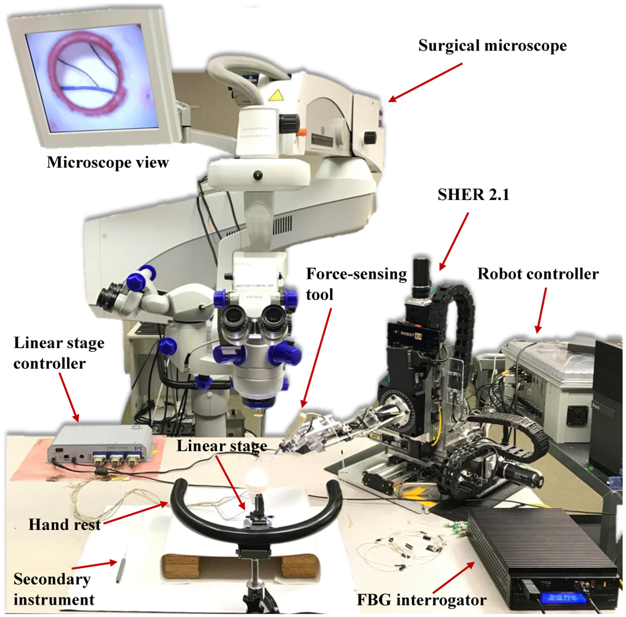
Robot-assisted retinal surgery experimental setup. It includes the SHER and its controller, surgical microscope, force-sensing tool. FBG interrogator, eye phantom, linear stage and its controller.
In order for robots to meet the safety requirements for human use, advanced sensing capabilities and control algorithms are being developed and implemented. This becomes even more necessary in eye surgery since the robot is dealing with highly delicate and ultra-fine tissue. Robots in retinal surgery should not only provide high precision for the tool tip and cancel the tremor but also appropriately handle the sclera forces and tip forces to enforce safety boundaries as well as the tool insertion depth to avoid collision with retina (shown in Fig. 2). Furthermore, these added sensors and controls would strategically enhance robotic capabilities, enabling them to perform advanced and high precision surgical tasks which are otherwise impossible for the unassisted human. In order to obtain micron scale visual precision at the tool tip for sub-retinal injections, [9], [10], [19], [20] have incorporated Optical Coherence Tomography (OCT) into robots. In [21], authors use reinforcement learning with an industrial robot to perform OCT-guided corneal needle insertion. OCT-based insertion depth and 3D position estimations of a needle tip beneath the retina, have also been recently proposed by Cheon et al. [22] and Zhou et al. [23], respectively. Computer vision algorithms have been used for robotic eye surgery [24], [25]. As a recent example, Becker et al. [26] used stereo vision to create virtual fixtures to improve needle tip positioning. Fiber Bragg Grating (FBG) sensors have also been integrated to surgical tools to measure the tip force and sclera forces in real time (Fsx and Fsy shown in Fig. 2) in order to enhance robot force measurement capabilities [27], [28]. Ebrahimi et al. developed a FBG-based framework for flexible instrument tip position estimation in robot-assisted eye surgery [29].
Fig. 2.
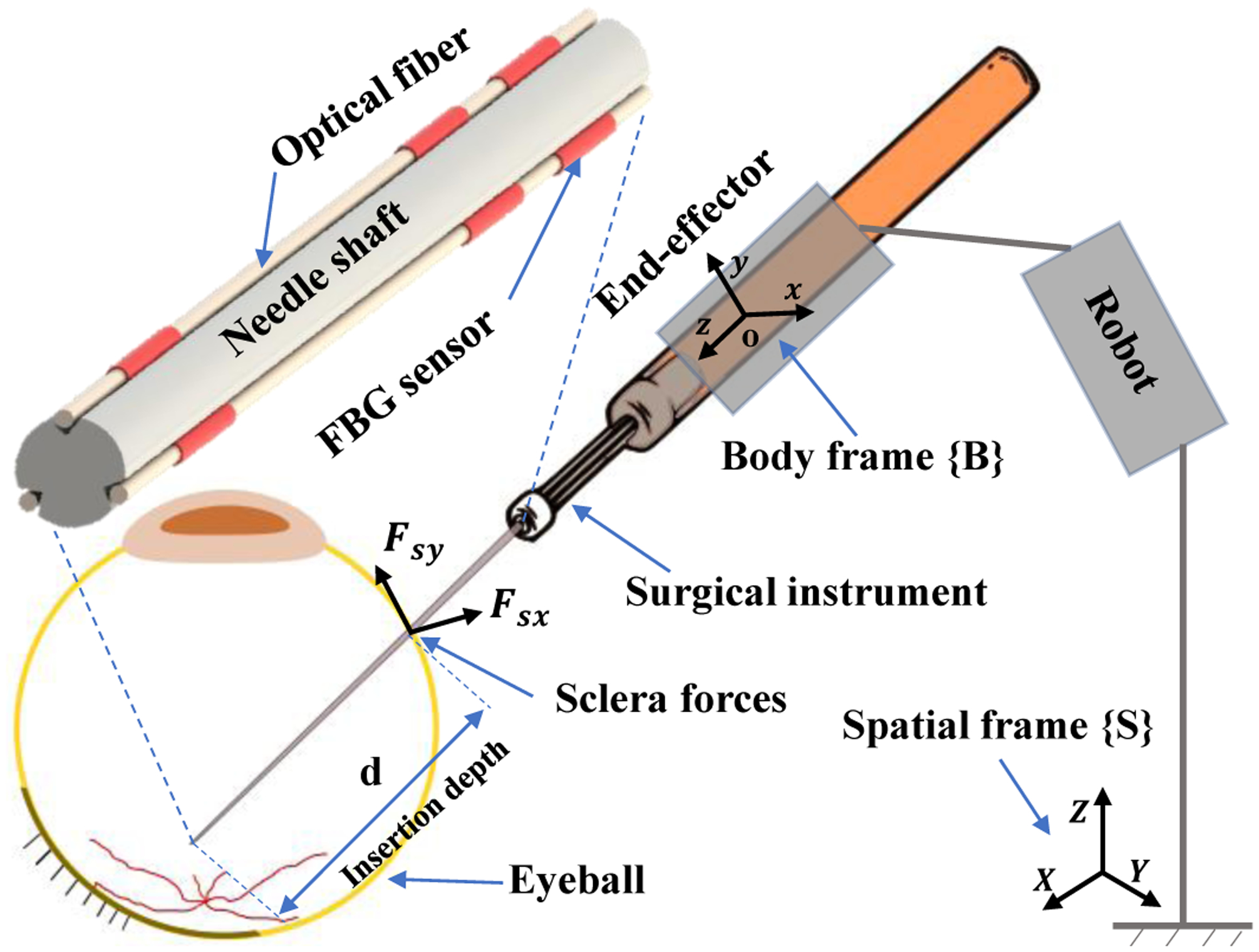
Schematic of the surgical tool attached to the robot. The spatial and body frames are attached to the robot base and to the robot end-effector, respectively.
Although major advances in instrument tip precision and safety have been made as indicated above, less attention has been paid to the relationship between the sclera and the tool shaft. During freehand surgery, surgeons perceive the scleral forces and rely on them to guide both the eye movements and the instrument inside of the eye. However, when a robot is used, either in a tele-operated or cooperative system, the milli-Newton scale, direct tactile sclera force feedback to the surgeon is damped or lost. Furthermore, as surgeons are working through a microscope which visualizes eyeball interior, there is no visual feedback from the tool-scleral interactions in robot-assisted surgery. It is still possible for a surgeon to unknowingly apply large sclera forces during a robot-assisted manipulation. We have previously demonstrated that using robots in such procedures, may increase the risk of high force to sclera events [30]. Such inadvertent force applications may impact the retinal tasks being performed or directly injure the scleral wall. One common approach to address this issue is the use of remote center of motion (RCM) mechanisms [14], [17]. However, the problem with RCM mechanisms is that they passively maintain the sclera forces in a prescribed safe range. Moreover, surgeons usually use a second instrument (e.g. a light pipe) during intraocular surgery and the forces resulting from the second tool increase sclera forces on the primary instrument (attached to the robot), even if RCM is present. In order to actively limit scleral forces during surgical maneuvers, He et al. [31], [32] have used a deep learning approach to predict unsafe sclera forces, and to counter them proactively to insure safety. The limitations of this method, however, include but are not limited to the large data sets required for training, and the occurrence of unreliable predictions due to network errors for untrained tool-retina interactions.
Contrary to the bulk of the research that addresses instrument tip control, in this study we evaluate sclera force control methods through comprehensive user studies with ophthalmic clinicians. We believe that managing forces between the tool and the tool’s point of entry into the eye is important to present and future robotic retinal surgery success. In prior work we introduced a real time adaptive control approach to keep the sclera forces and insertion depth within safe ranges [33], [34]. Moreover, the adaptive control for sclera forces was evaluated through preliminary studies, and was compared to virtual fixture approaches, with an assessment of patient safety and surgeon comfort [35]. In the present study, and based on our previous preliminary work, we have chosen two variants of the adaptive sclera force control method for a comprehensive evaluation with clinicians. In brief, ten ophthalmology clinicians were enrolled in robot-assisted user studies conducted in an operating room in Wilmer Eye Institute at the Johns Hopkins Hospital. The users were tasked to follow retinal vessels with a tool tip on a phantom eyeball. A piezo-actuated linear stage was utilized to simulate random motions of patient head which might occur when the patient is under anesthesia. Finally, the performance of each control method was analyzed and compared directly to the same clinician’s freehand manipulations (unassisted by the algorithm or robot). Using online scleral force information, the novel robot control framework could potentially generate useful robot behaviors that enhance patient safety, and provide intuitive and useful feedback to surgeons.
II. Robot Control Framework
The SHER is a 5-degree-of-freedom (DoF) robot which provides a steady-hand manipulation for users. Various surgical tools can be attached to the robot end-effector using a quick release mechanism. The robot enables users to perform tremorfree surgical maneuvers. The users and the robot both hold the surgical instrument handle and move it collaboratively to achieve surgical goals. In order to describe the robot motion, two coordinate frames are incorporated into the robot: the spatial coordinate frame {S} which is fixed to the robot base and the body coordinate frame {B} which is attached to the robot end-effector (Fig. 2). The rigid body transformation between {S} and {B} can be written as gsb(q) ∈ SE(3) as a function of joint angles .
| (1) |
In (1), the terms Rsb(q) ∈ SO(3) and are the rotation and translation parts of gsb, respectively. Using the product of exponential formula developed in [36], gsb can be written as follows:
| (2) |
where qi, i = 1, …, 5 is the ith element of the vector of joint angles q. gsb(0) indicates the initial relative configuration of frames {S} and {B} when q = 05×1. Each ξi = (vi, wi)T, where (vi)T and (wi)T are both in , is a twist coordinate representing the rigid body transformation associated with ith joint motion of the robot. For the prismatic joints of the robot (first three joints) wi is zero vector and vi is a unit vector along the prismatic joint direction written in frame {B}. For the revolute joints of the robot wi is the unit vector of rotation axis of the joint and vi is −wi × qi where qi is an arbitrary point on rotation axis [36]. Then, the 4 × 4 matrices in (2) can be constructed as follows:
| (3) |
where is a 3×3 skew symmetric matrix constructed by wi. Then, defining the body velocity of the of the frame {B} as , this velocity can be written in twist coordinates as written in (4) using the body Jacobian formula.
| (4) |
where is defined as follows.
| (5) |
In (4), is a vector in representing the body velocity of frame {B} written in twist coordinates. The terms and indicate the velocity of the origin of frame {B} and the angular velocity of the frame {B} both expressed in the frame {B}, respectively. In (5), Ad is the 6 × 6 adjoint transformation depending on the configuration of the robot [36].
A three-level hierarchy (Fig. 3) forms the control framework of the robot: 1) High-level controller 2) Mid-level optimizer 3) Low-level joint velocity controller which are explained as follows.
Fig. 3.
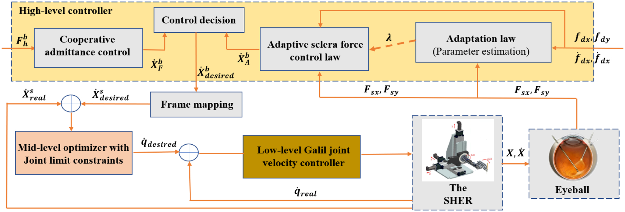
Block diagram for the closed-loop control system. It shows the high-level controller, the mid-level optimizer and the low-level joint velocity controller. The signals definitions include : user force, : end-effector desired body velocity, : end-effector desired spatial velocity, : end-effector real spatial velocity, : desired joint velocities, : real joint velocities, Fsx and Fsy: real slcera force components in frame {B}, fdx and fdy: desired slcera force components in frame {B}.
A. High-level controller
The high-level controller outputs the desired body velocity, , of the frame {B} in twist coordinates which is highlighted in yellow in Fig. 3. The high-level controller consists of two modes including cooperative admittance control and adaptive sclera force control which are represented in Fig. 3.
1). Cooperative admittance control mode:
The cooperative admittance control sets proportional to the generalized wrench at the origin of the frame {B} which is written in (6). The term and are the force and torques applied by the user to the surgical instrument handle after being transferred to the frame {B}. The superscript b indicates that the wrench is expressed in frame {B}.
| (6) |
In (6), is a 6 × 6 diagonal matrix with elements di, i = 1, …, 6 on the diagonal. This proportional assignment of desired velocity to the wrench creates an intuitive motion of the robot end-effector and the user can easily move the instrument to target position by exerting a proper wrench Fh to the tool handle.
2). Adaptive sclera force control mode:
In order to address the challenges of sclera force control in robot-assisted eye surgery we have proposed three different sclera force control laws in our prior work [35]. The approaches evaluated in [35] include the adaptive norm control (ANC), adaptive component control (ACC) and a force-based virtual fixture (VF) method. We evaluated these control methods in a preliminary study with two users. The results of [35] indicated that the VF method was not able to handle rapid changes in sclera force and was consequently ruled out for the current study. The basic idea behind the adaptive control methods is to define safe trajectories for sclera force components (fdx and fdy) and to control the robot to make the actual sclera forces (Fsx and Fsy) to follow these safe trajectories. Using Lyapunov it is shown in [37] for a 1-DoF velocity-controlled robot interacting with a flexible environment that the adaptive control approach will achieve this goal. We have customized that approach for sclera force control in robot-assisted eye surgery and suggested the ACC and the ANC methods. Therefore, the two scleral force safety-enhancing control modes that we consider here are the ANC and ACC methods which are further explained as follows:
• Adaptive component control for sclera force (ACC)
There are two sclera force components along the x and y directions of the body frame {B} (Fig. 2), respectively called Fsx and Fsy. The ACC method considers each component of sclera force independently. If the ith (i = x or y) component exceeds the safe level U, the ACCi method reduces the based on a desired safe reference trajectory for sclera force fdi (i = x or y). For the ACC control, the vector is generated based on (7) as follows:
| (7) |
where Cx and Cy are constant positives numbers. The variable δi (i = x or y) in (7) has a binary value (0 or 1). δi = 1 indicates that ACCi is activated and if it is zero the ACCi is deactivated. The variables αi (i = x or y) is an estimation of the sclera tissue stiffness along the i direction of frame {B} which are updated using the following adaptation laws:
| (8) |
As stated in [33], the combination of (7) and (8) makes the sclera force to converge to the safe reference trajectory fdi. As noted from (7), if δi is zero (meaning ACCi is deactivated) then the corresponding component of for the axis i will be simply produced based on the cooperative admittance control law. The desired reference trajectories for fsx is written in (9) which is based on what was preliminarily evaluated in [35]. For fsy a similar scenario can be imagined.
| (9) |
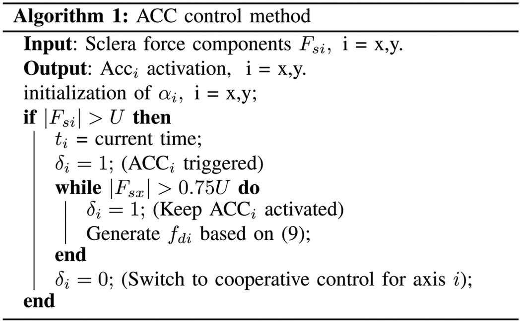
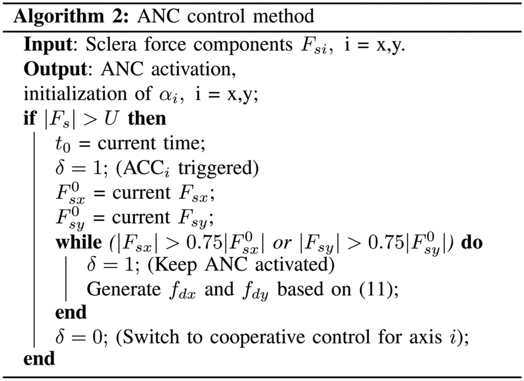
In (9), tx is the time when fsx exceeds the safe level. The logic for activating and deactivating the ACCi is written in Algorithm 1.
• Adaptive norm control for sclera force (ANC)
The alternative to the ACC method which deals with each component of sclera force independently, is the ANC algorithm in which both components of sclera force are reduced simultaneously. The control is activated when the 2-norm of sclera force vector reaches the limit U.
|
The control law will then obey (10).
| (10) |
In (10), Cx and Cy are positive constants. The adaptation law for the sclere tissue estimations (αx and αy) in (10) is similar to (8). δ which has a binary value is the activation indicator for ANC method. If δ = 1 it means that the ANC method is activated and if δ = 0 (indicating the deactivation of ANC method) then (10) will be identical to (6). Theoretically, the ANC method is more restrictive than the ACC control method as it reduces both components together and it provides less freedom for users, but the benefit should be higher effort with regard to maintaining scleral forces into prescribed safe ranges. The desired reference trajectories for the ANC method which are decreasing exponential functions, are written in (11).
| (11) |
In (11), t0 is the time when the magnitude of sclera force Fs exceeds the safe level U. The terms and are the values of Fsx and Fsy at t = t0, respectively. The activation algorithm for the ANC method is provided in Algorithm 2.
B. Mid-level optimizer and low-level controller
After finding the desired rigid body velocity of gsb in the frame {B}, we need to first express this vector in the spatial coordinate frame. This is done using the adjoint transformation which is given in (12):
| (12) |
Now the desired rigid body velocity of gsb in the spatial frame {S} can be computed as follows:
| (13) |
|
Because the robot is a 5-DoF robot and is in , desired velocity cannot be exactly achieved. Instead, the following optimization is solved to find the optimized joint velocities of the robot:
| (14) |
with the inequality constraints of:
| (15) |
In (15) the the terms and are the joint velocity limits and and are the bounds for joint angles. The joint position bounds are implemented using the limit switches and are not included in the mid-level optimizer procedure. The term in (14) is the spatial Jacobian and is related to body Jacobian defined in (4) using (16):
| (16) |
After solving the optimization (14), is sent to the low-level PID controller for joint velocities to be commanded to the actuators.
III. Experimental setup and experiment protocol
A. Experimental setup
The entire system for conducting the experiments was located in an operating room in the Wilmer Eye Institute at the Johns Hopkins Hospital as depicted in Fig. 1. The SHER 2.1 was used to conduct the experiments along with its embedded low-level joint velocity controller (Galil controller - Galil 4088, Galil, Rocklin, CA, USA).
A force-sensing surgical instrument equipped with Fiber Bragg Grating (FBG) optical sensors (Figs. 2 and 4-b) is attached to the robot. Three FBG fibers with diameter of 80 μm are attached along the micro-grooves on the instrument shaft. The architecture of the sensors and their calibration procedure which are elaborated in [27] and [33] enables the sensorized instrument to measure the Fsx and Fsy with accuracy of 1 mN in frame {B}. A FBG interrogator (sm130–700 from Micron Optics Inc., Atlanta, GA) is used to measure the wavelength associated with the light reflected by the optical sensors, Fig. 1.
Fig. 4.
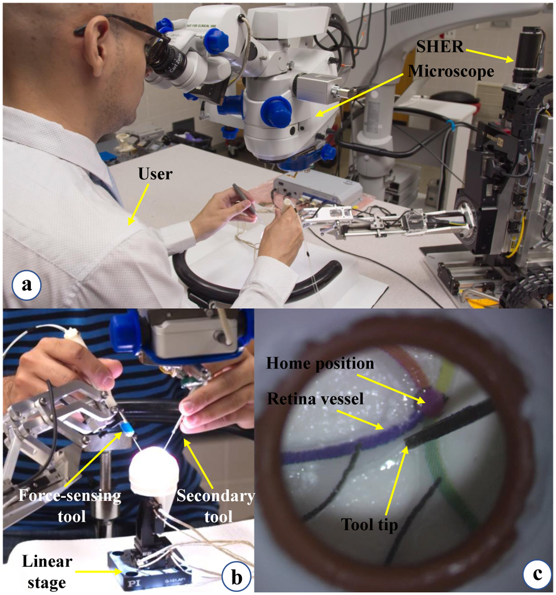
User study illustration. (a) The user is looking into the microscope and following the retinal vessels with the force-sensing tool tip. (b) This view shows how the user inserts the force-sensing and the secondary tools into the eyeball which is attached to the linear stage. (c) Microscope view showing the painted retinal vessels.
Users typically hold the force-sensing instrument in their dominant hand and a secondary tool in their non-dominant hand Fig. 4. For ease of manipulation, the secondary tool is provided but it does not have any force sensing capabilities. Of note, retinal surgery is typically performed bimanually.
A piezo-actuated linear stage (Q-Motion Stages, PI Motion and Positioning, MA, USA) is used to simulate patient disturbances (e.g. from patient head motion etc.) during the experiments (Figs. 1 and 4-b). The reason for adding the disturbance simulators is that these are a main source of sclera force variations during robot-assisted surgery, therefore simulating these disturbances simulates the real life system requirements. This insures the sufficiency of the control methods implemented. The piezo-actuated linear stage and its motion controller are depicted in Fig. 1. We programmed the motion controller to generate random one-dimentional step motions at random times to simulate patient head disturbance. First, the stage starts moving after Ts seconds which has a uniform distribution of U[5, 10] (s). Then the stage generate a step motion M based on a uniform distribution [−3, −1] ∪ [1, 3] (mm). After reaching the target position M, the stage waits there for a random time generated based on a uniform distribution U[1, 3] (s) and then returns to its origin. The procedure continues while the user is performing the experiments.
An eye phantom made of Silicon rubber is attached to the linear stage. There are four vessels with different colors depicted on the interior and posterior aspect of the eye phantom (Fig 4-c). These are used as the surgical targets during the experiments. A Zeiss surgical microscope is used for magnification of the eyeball interior. For controlling the robot a software program was utilized which was developed using the C++ CISST-SAW libraries [38].
B. Experiment Protocol
The goal of this study is to evaluate the ACC and ANC control methods for robot-assisted eye surgery during clinician use. After securing approval from the Johns Hopkins Institutional Review Board (IRB) with the protocol number HIRB00000943, we provided the opportunity for surgeon clinicians to participate in the experiments at the Wilmer Eye institute, Johns Hopkins Hospital, Baltimore, MD, USA. Ten clinicians (including retina residents and retina fellows) were enrolled in this study after obtaining written, informed consent. During the experiments, the users were asked to perform ”vessel following” which is a common task in vitreoretinal surgery. For each user the experiments consisted of three conditions including 1-ACC, 2-ANC and 3- freehand. Latin square was used to create random condition sequence for the experiments for each user. During all experiments the linear stage provided random lateral motions to the eyeball as explained in section III-A.
Each experimental condition involved ten trials of following four colored retinal vessels inside a phantom eyeball (Fig. 4-c). In each trial the sequence of colors to follow was a random permutation of the four colors. No identical sequence of four colors was presented to the user.
First, the entire system and the components were explained to each user (No user was considered an expert robot user). After having at least two minutes of training and then demonstrating basic familiarity with the robot and the force-sensing tool, each participant went through the following steps for each trial of the experiment:
Start the experiments by inserting the force-sensing tool and the secondary tool into the eyeball.
Keep the force-sensing instrument tip, which is held by the dominant hand close to the home position (Fig. 4-c) until a random sequence of four colors is read to the user by the instructor.
Follow the sequence of four retinal vessels with the tip of the force-sensing instrument.
Perform the ANC, ACC and the freehand groups, repeating for ten trials in each group.
At the end of data collection, the users were asked to subjectively rate, on a scale of 1 (very bad) to 5 (very well), how well each operation mode assisted with task performance. A questionnaire similar to NASA TLX was provided to the users to fill out regarding this part.
IV. Results and Discussion
For each of the users, all of the experiment data including sclera forces, insertion depth, robot position and velocity, time information and etc. were recorded during the freehand, ACC and ANC experiments. In our prior work [39], the limit for sclera force was argued to be 120 mN. This was obtained by analyzing the results for a freehand eyeball manipulation of an expert surgeon and does not necessarily indicate a limit above which the sclera will be damaged. Considering this limit and to have a safety margin, the sclera force control methods in this paper are activated in advance at 100 mN (U is set to 100 mN in Algorithms 1 and 2) such that the robot will have enough time to prevent the sclera force from reaching 120 mN. The activation force for adaptive controls (U) is flexible and can be set to any other value if the safety limit should be changed.
A time window of sclera forces for freehand, ACC and the ANC experiments as a sample for one of the users are plotted in Figs. 5, 6 and 7, respectively. Fig. 5 depicts the magnitude of sclera forces for the freehand experiment for one of the users. This figure indicates that the clinician occasionally oversteps the 120 mN limit. The red short lines in the Fsx and Fsy plots for Figs. 6 and 7 indicate the reference safe trajectory attributed to each component of sclera force (fdx or fdy) for the period when the ACC or ANC controls are activated. The third subplots in Figs. 6 and 7 show the magnitude of scelra forces for ACC and ANC, respectively. As it is observed, although the ACC method is able to generally maintain the forces in a safe range, a few events of exceeding the safe level are recorded. The ANC method reduces the number of high force events (greater than 120 mN) as compared to the ACC method. In other words, as it can be seen the ANC method is able to better keep the Fs under the 120 mN limit. It is noted that the sclera force components sometimes do not perfectly follow the desired trajectories which are plotted in red. Such force disturbances are often attributed to the secondary tool use. The secondary tool (Fig. 4-b) can move the eyeball, therefore, implying scleral forces on the force-sensing tool. Although this source of disturbance is countered by the robot in real time to provide safe force maintenance, the robot is not perfectly able to keep the sclera forces on desired trajectories. It does however still limit the high force events to the sclera as it can be seen in Figs. 6 and 7. The time spent at forces over 120 mN, the experiments total time, and the average sclera force are calculated for all clinicians and represented in boxplotes in Figs. 8–10. Fig. 9 shows that the ANC method significantly reduces the time spent at sclera forces greater than the 120 mN limit, although the ACC method also maintains the sclera forces as safe as the freehand case. Improvements in force reduction for safe tool manipulation resulting from both the ACC and ANC methods are countered by increases in the total time to complete the experiment, as it is seen in Fig. 10. Fig. 8 indicates that in the freehand case, the average of scelral forces for some clinicians can go as high as 150 mN. However, both the ANC and ACC methods limit the average sclera forces for all users to a lower and more consistent force level. The reason for this is that both control methods allow the robot to counter the source of scleral force increase (e.g. surgeon inadvertently increases the force, the rotational force from the secondary instrument increases the force) and to always keep the force in limits.
Fig. 5.

Plot for sclera force in freehand experiment for one of the users.
Fig. 6.
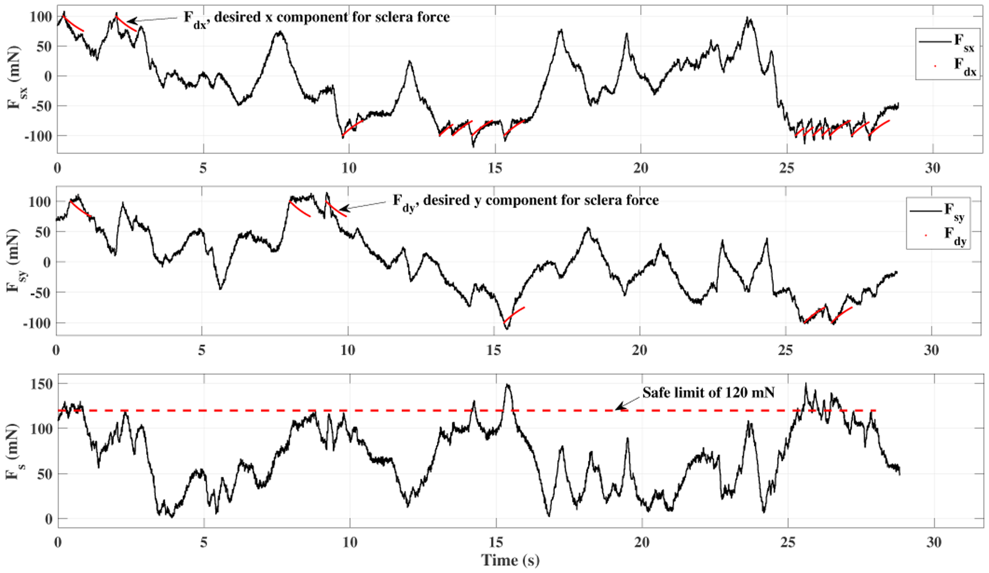
Plot for sclera force in ACC experiment for one of the users.
Fig. 7.
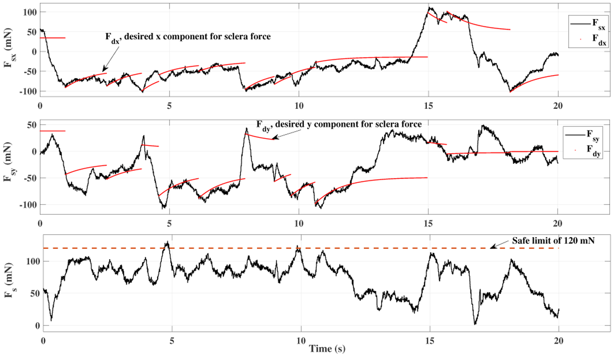
Plot for sclera force in ANC experiment for one of the users.
Fig. 8.
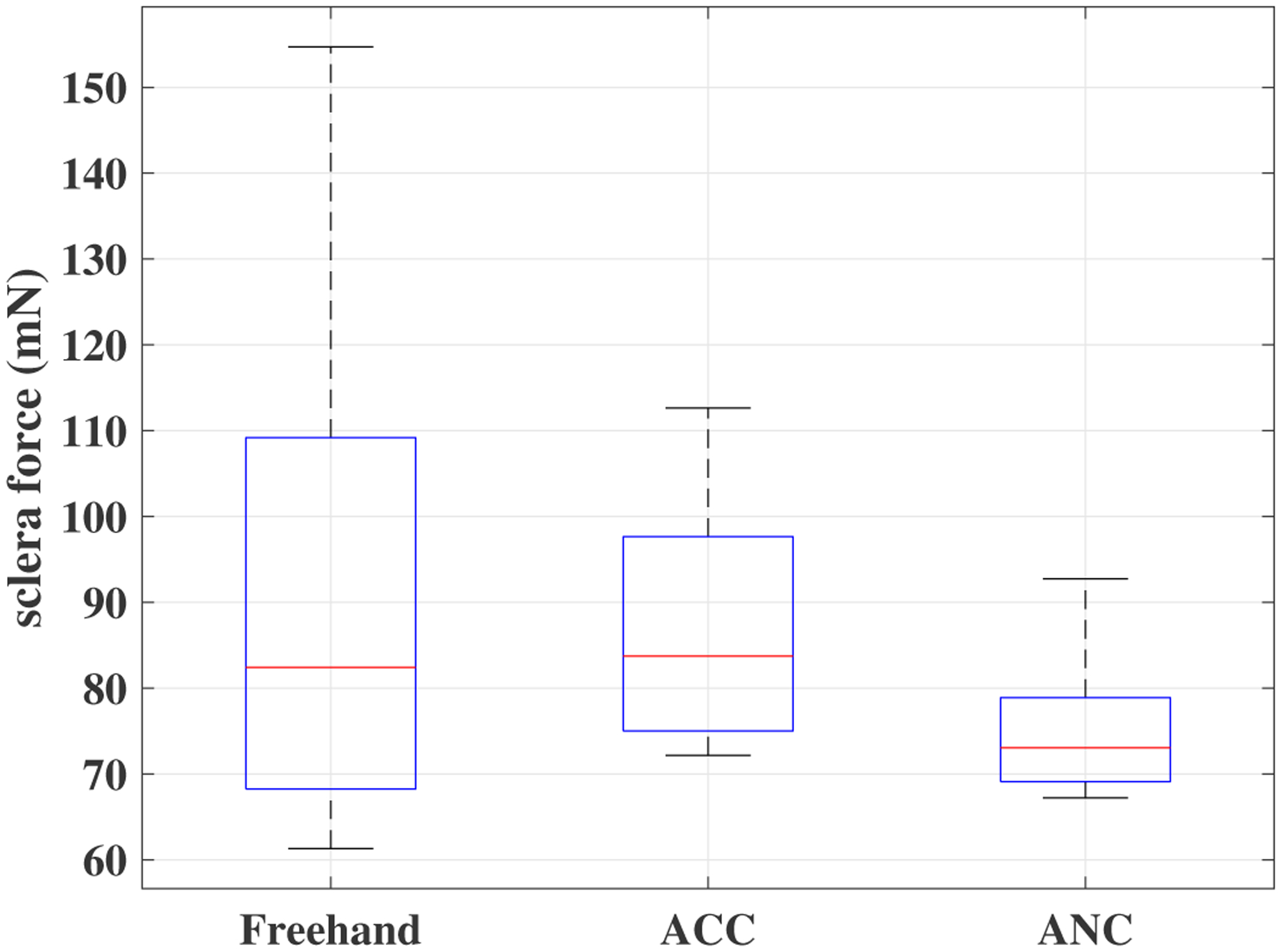
Boxplots of sclera forces for all clinicians for the freehand, ACC and the ANC experiments.
Fig. 10.
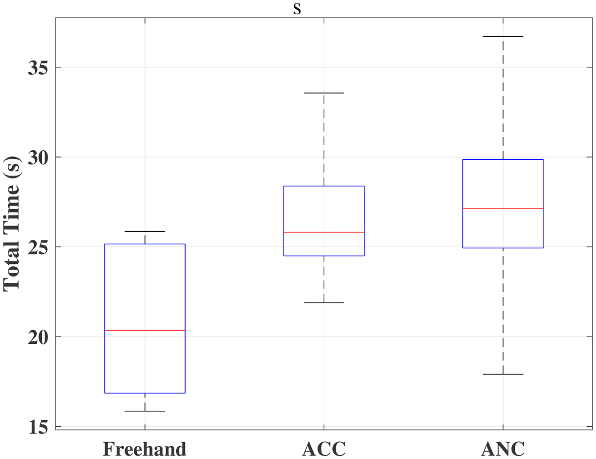
Boxplots of total time for all clinicians for the freehand, ACC and the ANC experiments.
Fig. 9.
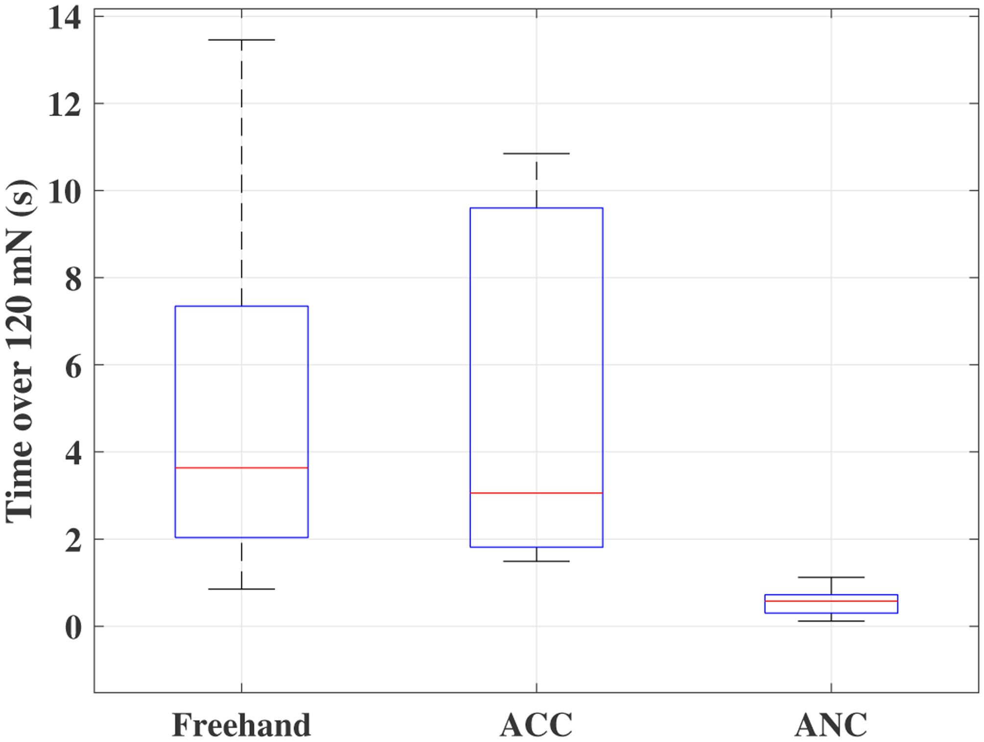
Boxplots of time spent on forces more than 120 mN for all clinicians for the freehand, ACC and the ANC experiments.
Table I provides the average results for all users. The fourth column (time percentage spent over 120 mN) is the division of the corresponding average values of the third column (total time above 120 mN (s)) to the second column (total Time (s)). As it can be seen the ANC method is able to keep the unsafe time percentage as low as 2%.
TABLE I.
Average results for all users over all experiments. The value in the parenthesis indicates the standard deviation.
| Total Time (s) | Total time above 120 mN (s) | Time percentage spent over 120 (mN) | Average sclera force (mN) | |
|---|---|---|---|---|
| Freehand | 21.0 (2.4) | 5.0 (2.4) | 24% | 92.3 (53.4) |
| ACC | 26.6 (3.2) | 5.0 (2.3) | 19% | 87.4 (32.0) |
| ANC | 27.4 (3.4) | 0.6 (0.4) | 2% | 75.2 (24.3) |
Table II compares the results provided in Table I and provides the corresponding p-values. For example, we can see from Table II that the p-value for comparing the freehand-ANC unsafe times (time over 120 mN) is 0.005. This indicates that the reduction of average unsafe time from 5(s) to 0.6(s) from freehand to ANC as indicated in Table I is statistically significant. In [8], the authors have conducted a user study to compare vitreoretinal robot-assisted and manual surgeries. Their results indicate that the robot-assisted case is significantly slower than the manual surgery for both novices and experienced surgeons. The total time results represented in Table I, is consistent with the earlier results obtained in [8]. As we can see, the average total time for the freehand experiment is less than the ACC and ANC conditions. The p-values provided in Table II indicates that this increase in the experiment total time when moving from freehand to robot-assisted is statistically significant.
TABLE II.
p-values for the results provided in Table I.
| Sclera Force | ANC | ||
| - | 0.67 | 0.13 | |
| 0.67 | - | 0.03 | |
| ANC | 0.13 | 0.03 | - |
| Total Time | ANC | ||
| - | 0.004 | 0.005 | |
| 0.004 | - | 0.7 | |
| ANC | 0.005 | 0.7 | - |
| Time over 120 | ANC | ||
| - | 0.97 | 0.005 | |
| 0.97 | - | 0.002 | |
| ANC | 0.005 | 0.002 | - |
The NASA TLX questionnaire results are summarized in the spider plot shown in Fig. 11. Within the questionnaire the quality of six parameters of user performance (meaning the quality of performing surgical tasks and technical maneuvers related to the surgical procedures), physical demand, comfort, ease of targeting the tool tip, nature of the block from the robot, frustration for each of the freehand, ANC and ACC methods were requested of the users. The corresponding p-values for the questionnaire results are shown in Table III to see if the questionnaire results are statistically significant. As it is shown the results for ACC and ANC methods are closely overlapping indicating that they showed little user preference for one or the other. This is further supported by looking at the large p-values obtained when comparing the questionnaire results for the ACC and ANC methods as shown in the last column of Table III.
Fig. 11.
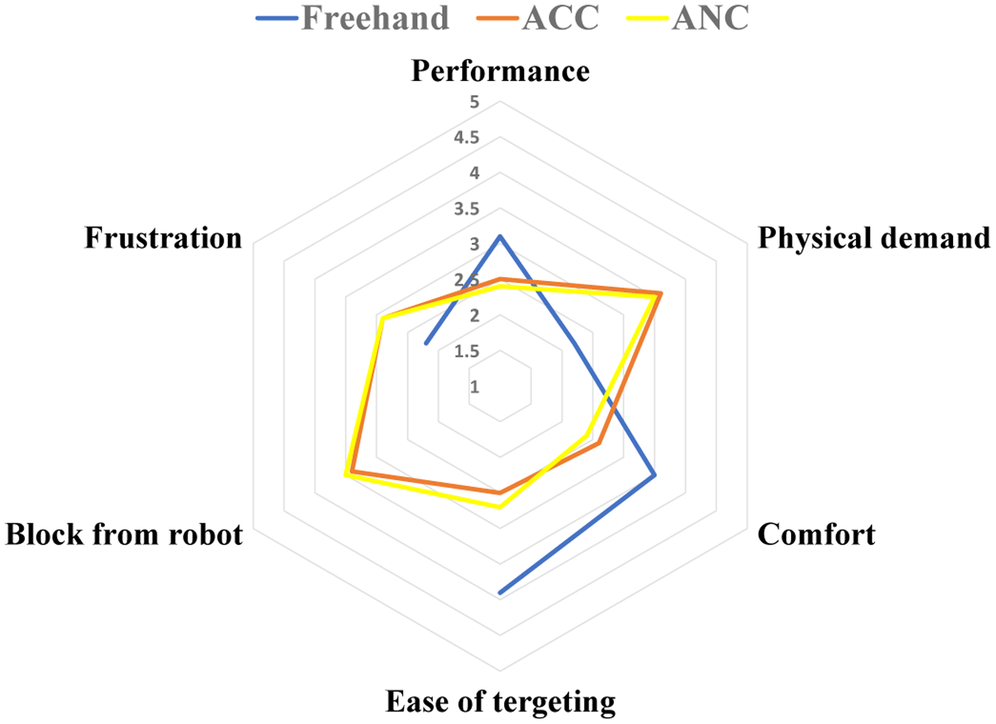
Questionnaire results scaled from 1(very bad) to 5(very good).
TABLE III.
p-values for the questionnaire results provided in Fig. 11.
| P-values | Freehand vs ACC | Freehand vs ANC | ACC vs ANC |
|---|---|---|---|
| Performance | 0.1892 | 0.0637 | 0.8297 |
| Physical demand | 0.0111 | 0.0172 | 0.8619 |
| Comfort | 0.0401 | 0.0094 | 0.6669 |
| Ease of targeting | 0.0033 | 0.0013 | 0.6652 |
| Block from robot | - | - | 0.8086 |
| Frustration | 0.2295 | 0.1964 | 1 |
For the freehand case which is plotted blue in Fig. 11, the parameter ”block from robot” does not have any meaning so it is left blank. From Table III and Fig. 11, we can see that for the parameters of ”physical demand”, ”comfort” and ”ease of targeting the tool”, the freehand case is preferred by the users and this result is statistically significant. The reason is that the users felt the robot was hindering their manipulation whenever the ANC or the ACC controls were activated.
The clinicians reported that they had to apply larger forces to move the robot toward their desired location as compared to the freehand procedure. At these early phases of learning most wanted less resistance from the robot. This was the dominant complaint of early robot users. Based on equations (7) and 10, we can see neither of the control methods interfere with the rotational velocities of the end-effector which are the last three elements of the vector . When the instrument is inside of the eye, a user experienced with the robot utilizes primarily the rotational velocities of the end-effector, i.e. they apply torque to the instrument handle (e.g. similar to a spherical joint motion), to reach different locations inside of the eyeball. In other words, because only the first two elements of are used for ACC and ANC activation, if the user has mastered the use of rotational velocities for surgery, the amount of interference from the robot with the surgeon’s maneuvers, when the ACC or the ANC controls are triggered, will be minimally felt. This method of manipulating the robot may be a matter of learning curve as it was mentioned by one of the users who performed the ANC experiments after ACC (had enough training with the robot before starting ANC) and commented that the ANC method seemed easier than ACC. As stated in section II-A.2, the ANC is more preventive and is supposed to allow less comfort for the user. We attribute this preference of ANC over ACC to be the result of learning curve. Regarding this issue, another clinician commented that it would be desirable if they had an ongoing discretion as to when switch between the safety controls (ANC or ACC) and the robot regular motion during the surgery.
Therefore, although the ANC and ACC significantly contribute to sclera force safety in a robot-assisted surgery, the users feel more comfortable performing the surgery freehand. As elaborated above, this can be related to learning curve as the users did not have any experience with a robot-assisted eye surgery before. The clinicians may feel more comfortable using the robot integrated with safety-enhancing controls if they receive enough training.
V. Conclusion
In this paper we have evaluated two variants of an adaptive sclera force control method. These control methods which were implemented on the SHER can autonomously cause the robot to reduce the forces between the tool and its scleral entry point, when they exceed safe boundaries. The evaluation was carried out by enrolling ten robot-novice ophthalmology clinicians in simulated robot-assisted eye surgeries while the control methods were implemented on the SHER. Based on the results and statistical analysis, we conclude that the ACC and the ANC methods are able to maintain sclera forces within safe boundaries, potentially enhancing safety for retinal surgery patients undergoing robot assisted procedures. It is noted that for robot-novice users the test procedure was more comfortable to be performed freehand, and took longer when using the robot assistance. This was true for both the ACC and ANC control methods. It is possible that significant training may allow users to increase their acceptance of the control methods during retinal surgery. This is potentially important as both control methods successfully reduced the application of forces to the eye.
A future direction of this work is to modify and refine the control methods and the corresponding reference trajectories to enhance surgeon acceptance and comfort while limiting the application of unsafe forces to the eye. It is possible that robot control is most strategically utilized only during selected portions of a given procedure. A user study with clinicians sufficiently trained with the robot compared to inexperienced users is also a potential next area of study.
Acknowledgments
This work was supported by U.S. National Institutes of Health under grant numbers of 1R01EB023943-01 and 1R01EB025883-01, Link Foundation, Research to Prevent Blindness, New York, New York, USA, gifts by the J. Willard and Alice S. Marriott Foundation, the Gale Trust, Mr. Herb Ehlers, Mr. Bill Wilbur, Mr. and Mrs. Rajandre Shaw, Ms. Helen Nassif, Ms Mary Ellen Keck, Don and Maggie Feiner, and Mr. Ronald Stiff, and Johns Hopkins University internal funds.
Contributor Information
Ali Ebrahimi, Laboratory for Computational Sensing and Robotics at the Johns Hopkins University, Baltimore, MD 21218 USA..
Müller G. Urias, Wilmer Eye Institute, Johns Hopkins Hospital, Baltimore, MD 21287 USA.
Niravkumar Patel, Laboratory for Computational Sensing and Robotics at the Johns Hopkins University, Baltimore, MD 21218 USA..
Russell H. Taylor, Laboratory for Computational Sensing and Robotics at the Johns Hopkins University, Baltimore, MD 21218 USA..
Peter Gehlbach, Wilmer Eye Institute, Johns Hopkins Hospital, Baltimore, MD 21287 USA..
Iulian Iordachita, Laboratory for Computational Sensing and Robotics at the Johns Hopkins University, Baltimore, MD 21218 USA..
References
- [1].Friedman DS, O’Colmain BJ, Munoz B, Tomany SC, McCarty C, De Jong P, Nemesure B, Mitchell P, Kempen J et al. , “Prevalence of age-related macular degeneration in the united states,” Arch ophthalmol, vol. 122, no. 4, pp. 564–572, 2004. [DOI] [PubMed] [Google Scholar]
- [2].Wong WL, Su X, Li X, Cheung CMG, Klein R, Cheng C-Y, and Wong TY, “Global prevalence of age-related macular degeneration and disease burden projection for 2020 and 2040: a systematic review and meta-analysis,” The Lancet Global Health, vol. 2, no. 2, pp. e106–e116, 2014. [DOI] [PubMed] [Google Scholar]
- [3].Song P, Xu Y, Zha M, Zhang Y, and Rudan I, “Global epidemiology of retinal vein occlusion: a systematic review and meta-analysis of prevalence, incidence, and risk factors,” Journal of global health, vol. 9, no. 1, 2019. [DOI] [PMC free article] [PubMed] [Google Scholar]
- [4].Riviere CN and Jensen PS, “A study of instrument motion in retinal microsurgery,” in Proceedings of the 22nd Annual International Conference of the IEEE Engineering in Medicine and Biology Society (Cat. No. 00CH37143), vol. 1. IEEE, 2000, pp. 59–60. [Google Scholar]
- [5].Bynoe LA, Hutchins RK, Lazarus HS, and Friedberg MA, “Retinal endovascular surgery for central retinal vein occlusion: initial experience of four surgeons,” Retina, vol. 25, no. 5, pp. 625–632, 2005. [DOI] [PubMed] [Google Scholar]
- [6].Chan A, Duker JS, Ko TH, Fujimoto JG, and Schuman JS, “Normal macular thickness measurements in healthy eyes using stratus optical coherence tomography,” Archives of ophthalmology, vol. 124, no. 2, pp. 193–198, 2006. [DOI] [PMC free article] [PubMed] [Google Scholar]
- [7].Ueta T, Nakano T, Ida Y, Sugita N, Mitsuishi M, and Tamaki Y, “Comparison of robot-assisted and manual retinal vessel microcannulation in an animal model,” British Journal of Ophthalmology, vol. 95, no. 5, pp. 731–734, 2011. [DOI] [PubMed] [Google Scholar]
- [8].Jacobsen MF, Konge L, Alberti M, la Cour M, Park YS, and Thomsen ASS, “Robot-assisted vitreoretinal surgery improves surgical accuracy compared with manual surgery: A randomized trial in a simulated setting,” RETINA, 2020. [DOI] [PMC free article] [PubMed] [Google Scholar]
- [9].Yu H, Shen J-H, Shah RJ, Simaan N, and Joos KM, “Evaluation of microsurgical tasks with oct-guided and/or robot-assisted ophthalmic forceps,” Biomedical optics express, vol. 6, no. 2, pp. 457–472, 2015. [DOI] [PMC free article] [PubMed] [Google Scholar]
- [10].Charreyron SL, Boehler Q, Danun A, Mesot A, Becker M, and Nelson BJ, “A magnetically navigated microcannula for subretinal injections,” IEEE Transactions on Biomedical Engineering, 2020. [DOI] [PubMed] [Google Scholar]
- [11].Nasseri MA, Eder M, Nair S, Dean E, Maier M, Zapp D, Lohmann CP, and Knoll A, “The introduction of a new robot for assistance in ophthalmic surgery,” in 2013 35th Annual International Conference of the IEEE Engineering in Medicine and Biology Society (EMBC). IEEE, 2013, pp. 5682–5685. [DOI] [PubMed] [Google Scholar]
- [12].Tanaka S, Harada K, Ida Y, Tomita K, Kato I, Arai F, Ueta T, Noda Y, Sugita N, and Mitsuishi M, “Quantitative assessment of manual and robotic microcannulation for eye surgery using new eye model,” The International Journal of Medical Robotics and Computer Assisted Surgery, vol. 11, no. 2, pp. 210–217, 2015. [DOI] [PubMed] [Google Scholar]
- [13].He C, Huang L, Yang Y, Liang Q, and Li Y, “Research and realization of a master-slave robotic system for retinal vascular bypass surgery,” Chinese Journal of Mechanical Engineering, vol. 31, no. 1, p. 78, 2018. [Google Scholar]
- [14].Wilson JT, Gerber MJ, Prince SW, Chen C-W, Schwartz SD, Hubschman J-P, and Tsao T-C, “Intraocular robotic interventional surgical system (iriss): Mechanical design, evaluation, and master–slave manipulation,” The International Journal of Medical Robotics and Computer Assisted Surgery, vol. 14, no. 1, p. e1842, 2018. [DOI] [PubMed] [Google Scholar]
- [15].Li Z, Shahbazi M, Patel N, Sullivan EO, Zhang H, Vyas K, Chalasani P, Deguet A, Gehlbach PL, Iordachita I et al. , “Hybrid robotic-assisted frameworks for endomicroscopy scanning in retinal surgeries,” arXiv preprint arXiv:1909.06852, 2019. [DOI] [PMC free article] [PubMed]
- [16].Fleming I, Balicki M, Koo J, Iordachita I, Mitchell B, Handa J, Hager G, and Taylor R, “Cooperative robot assistant for retinal microsurgery,” in International conference on medical image computing and computer-assisted intervention. Springer, 2008, pp. 543–550. [DOI] [PubMed] [Google Scholar]
- [17].Gijbels A, Smits J, Schoevaerdts L, Willekens K, Vander Poorten EB, Stalmans P, and Reynaerts D, “In-human robot-assisted retinal vein cannulation, a world first,” Annals of Biomedical Engineering, pp. 1–10, 2018. [DOI] [PubMed] [Google Scholar]
- [18].Edwards T, Xue K, Meenink H, Beelen M, Naus G, Simunovic M, Latasiewicz M, Farmery A, de Smet M, and MacLaren R, “First-in-human study of the safety and viability of intraocular robotic surgery,” Nature Biomedical Engineering, p. 1, 2018. [DOI] [PMC free article] [PubMed] [Google Scholar]
- [19].Nasseri MA, Maier M, and Lohmann CP, “A targeted drug delivery platform for assisting retinal surgeons for treating age-related macular degeneration (amd),” in 2017 39th Annual International Conference of the IEEE Engineering in Medicine and Biology Society (EMBC). IEEE, 2017, pp. 4333–4338. [DOI] [PubMed] [Google Scholar]
- [20].de Smet MD, Meenink TC, Janssens T, Vanheukelom V, Naus GJ, Beelen MJ, Meers C, Jonckx B, and Stassen J-M, “Robotic assisted cannulation of occluded retinal veins,” PloS one, vol. 11, no. 9, p. e0162037, 2016. [DOI] [PMC free article] [PubMed] [Google Scholar]
- [21].Keller B, Draelos M, Zhou K, Qian R, Kuo AN, Konidaris G, Hauser K, and Izatt JA, “Optical coherence tomography-guided robotic ophthalmic microsurgery via reinforcement learning from demonstration,” IEEE Transactions on Robotics, 2020. [DOI] [PMC free article] [PubMed] [Google Scholar]
- [22].Cheon GW, Gonenc B, Taylor RH, Gehlbach PL, and Kang JU, “Motorized microforceps with active motion guidance based on common-path ssoct for epiretinal membranectomy,” IEEE/ASME Transactions on Mechatronics, vol. 22, no. 6, pp. 2440–2448, 2017. [DOI] [PMC free article] [PubMed] [Google Scholar]
- [23].Zhou M, Huang K, Eslami A, Roodaki H, Zapp D, Maier M, Lohmann CP, Knoll A, and Nasseri MA, “Precision needle tip localization using optical coherence tomography images for subretinal injection,” in 2018 IEEE International Conference on Robotics and Automation (ICRA). IEEE, 2018, pp. 1–8. [Google Scholar]
- [24].Braun D, Yang S, Martel JN, Riviere CN, and Becker BC, “Eyeslam: Real-time simultaneous localization and mapping of retinal vessels during intraocular microsurgery,” The International Journal of Medical Robotics and Computer Assisted Surgery, vol. 14, no. 1, p. e1848, 2018. [DOI] [PMC free article] [PubMed] [Google Scholar]
- [25].Yang S, Martel JN, Lobes LA Jr, and Riviere CN, “Techniques for robot-aided intraocular surgery using monocular vision,” The International journal of robotics research, vol. 37, no. 8, pp. 931–952, 2018. [DOI] [PMC free article] [PubMed] [Google Scholar]
- [26].Becker BC, MacLachlan RA, Lobes LA, Hager GD, and Riviere CN, “Vision-based control of a handheld surgical micromanipulator with virtual fixtures,” IEEE Transactions on Robotics, vol. 29, no. 3, pp. 674–683, 2013. [DOI] [PMC free article] [PubMed] [Google Scholar]
- [27].He X, Balicki M, Gehlbach P, Handa J, Taylor R, and Iordachita I, “A multi-function force sensing instrument for variable admittance robot control in retinal microsurgery,” in Robotics and Automation (ICRA), 2014 IEEE International Conference on. IEEE, 2014, pp. 1411–1418. [DOI] [PMC free article] [PubMed] [Google Scholar]
- [28].Smits J, Ourak M, Gijbels A, Esteveny L, Borghesan G, Schoevaerdts L, Willekens K, Stalmans P, Lankenau E, Schulz-Hildebrandt H et al. , “Development and experimental validation of a combined fbg force and oct distance sensing needle for robot-assisted retinal vein cannulation,” in 2018 IEEE international conference on robotics and automation (ICRA). IEEE, 2018, pp. 129–134. [Google Scholar]
- [29].Ebrahimi A, Alambeigi F, Sefati S, Patel N, He C, Gehlbach PL, and Iordachita I, “Stochastic force-based insertion depth and tip position estimations of flexible fbg-equipped instruments in robotic retinal surgery,” IEEE/ASME Transactions on Mechatronics, 2020. [DOI] [PMC free article] [PubMed] [Google Scholar]
- [30].He C, Ebrahimi A, Roizenblatt M, Patel N, Yang Y, Gehlbach PL, and Iordachita I, “User behavior evaluation in robot-assisted retinal surgery,” in 2018 27th IEEE International Symposium on Robot and Human Interactive Communication (RO-MAN). IEEE, 2018, pp. 174–179. [DOI] [PMC free article] [PubMed] [Google Scholar]
- [31].He C, Patel N, Ebrahimi A, Kobilarov M, and Iordachita I, “Preliminary study of an rnn-based active interventional robotic system (airs) in retinal microsurgery,” International journal of computer assisted radiology and surgery, vol. 14, no. 6, pp. 945–954, 2019. [DOI] [PMC free article] [PubMed] [Google Scholar]
- [32].He C, Patel N, Shahbazi M, Yang Y, Gehlbach PL, Kobilarov M, and Iordachita I, “Toward safe retinal microsurgery: Development and evaluation of an rnn-based active interventional control framework,” IEEE Transactions on Biomedical Engineering, 2019. [DOI] [PMC free article] [PubMed] [Google Scholar]
- [33].Ebrahimi A, Patel N, He C, Gehlbach P, Kobilarov M, and Iordachita I, “Adaptive control of sclera force and insertion depth for safe robot-assisted retinal surgery,” in 2019 International Conference on Robotics and Automation (ICRA). IEEE, 2019, pp. 9073–9079. [DOI] [PMC free article] [PubMed] [Google Scholar]
- [34].Ebrahimi A, He C, Patel N, Kobilarov M, Gehlbach P, and Iordachita I, “Sclera force control in robot-assisted eye surgery: Adaptive force control vs. auditory feedback,” in 2019 International Symposium on Medical Robotics (ISMR). IEEE, 2019, pp. 1–7. [DOI] [PMC free article] [PubMed] [Google Scholar]
- [35].Ebrahimi A, Alambeigi F, Zimmer-Galler IE, Gehlbach P, Taylor RH, and Iordachita I, “Toward improving patient safety and surgeon comfort in a synergic robot-assisted eye surgery: A comparative study,” in IEEE/RSJ International Conference on Intelligent Robots and Systems (IROS). IEEE, 2019, p. 7075. [DOI] [PMC free article] [PubMed] [Google Scholar]
- [36].Murray RM, Li Z, Sastry SS, and Sastry SS, A mathematical introduction to robotic manipulation. CRC press, 1994. [Google Scholar]
- [37].Roy J and Whitcomb LL, “Adaptive force control of position/velocity controlled robots: theory and experiment,” IEEE Transactions on Robotics and Automation, vol. 18, no. 2, pp. 121–137, 2002. [Google Scholar]
- [38].Kazanzides P, Chen Z, Deguet A, Fischer GS, Taylor RH, and DiMaio SP, “An open-source research kit for the da vinci® surgical system,” in 2014 IEEE international conference on robotics and automation (ICRA). IEEE, 2014, pp. 6434–6439. [Google Scholar]
- [39].Ebrahimi A, He C, Roizenblatt M, Patel N, Sefati S, Gehlbach P, and Iordachita I, “Real-time sclera force feedback for enabling safe robot assisted vitreoretinal surgery,” in 2018 40th Annual International Conference of the IEEE Engineering in Medicine and Biology Society (EMBC). IEEE, 2018, pp. 3650–3655. [DOI] [PMC free article] [PubMed] [Google Scholar]


