Abstract
Mitral valve disease is common. Mitral regurgitation is the second most frequent indication for valve surgery in Europe and despite the decline of rheumatic fever in Western societies, mitral stenosis of any aetiology is a regular finding in all echo departments. Mitral valve disease is, therefore, one of the most common pathologies encountered by echocardiographers, as both a primary indication for echocardiography and a secondary finding when investigating other cardiovascular disease processes. Transthoracic, transoesophageal and exercise stress echocardiography play a crucial role in the assessment of mitral valve disease and are essential to identifying the aetiology, mechanism and severity of disease, and for helping to determine the appropriate timing and method of intervention. This guideline from the British Society of Echocardiography (BSE) describes the assessment of mitral regurgitation and mitral stenosis, and replaces previous BSE guidelines that describe the echocardiographic assessment of mitral anatomy prior to mitral valve repair surgery and percutaneous mitral valvuloplasty. It provides a comprehensive description of the imaging techniques (and their limitations) employed in the assessment of mitral valve disease. It describes a step-wise approach to identifying: aetiology and mechanism, disease severity, reparability and secondary effects on chamber geometry, function and pressures. Advanced echocardiographic techniques are described for both transthoracic and transoesophageal modalities, including TOE and exercise testing.
Keywords: mitral regurgitation, mitral stenosis, transthoracic echocardiography, tranoesophageal echocardiography
Introduction: basic concepts
Mitral valve anatomy
Normal mitral valve anatomy
The normal mitral valve (MV) sits at the junction between the left atrium (LA) and left ventricle (LV). It is a complex anatomical structure composed of several distinct but contiguous structures: a fibro-muscular annulus, two leaflets, tendinous chords and papillary muscles (1). In order to identify abnormal mitral anatomy by echocardiography and accurately diagnose disease severity, it is essential that echocardiographers possess a comprehensive understanding of normal mitral valve structure and function (1, 2).
Leaflets
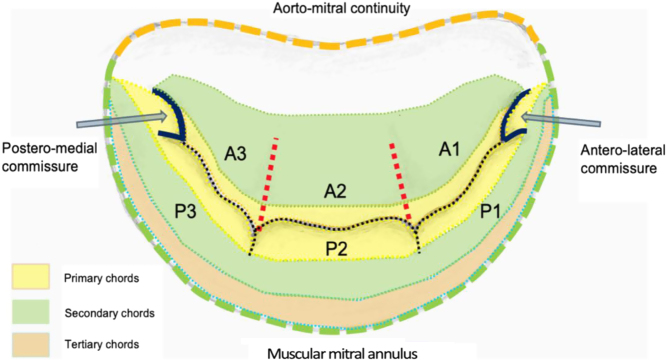
Standard imaging practice describes the two MV leaflets according to their general anatomical positions, anterior and posterior (3, 4). The geometry of the anterior and posterior leaflets is quite different. The posterior leaflet is short in length, usually, 11–14 mm, inserting along two-thirds of the annular circumference (5, 6). In contrast, the anterior leaflet is longer, normally 18–24 mm, but involves only one-third of the total annular circumference (6); the anterior and posterior leaflets meet in the margins at the antero-lateral and postero-medial commissures (Fig. 1) (2). Along the free edge of the posterior leaflet are a series of indentations that divide the posterior leaflet into three scallops of roughly equal size: P1, P2 and P3 (3). Although similar indentations are not present on the anterior leaflet, the corresponding regions opposing the posterior scallops are labelled A1, A2 and A3 (3). Where the two leaflet tips meet is described as the zone of coaptation. The coaptation zone (leaflet apposition) is at least 5 mm in height in a competent mitral valve (1).
Figure 1.
Mitral valve anatomy – ventricular surface (1).
Chordae tendineae
The mitral leaflets are in continuation with the LV via support chords that extend from the papillary muscle, known as chordae tendineae (3). The chordae tendineae provide varying degrees of tensile support throughout systole. The classification of either primary, secondary or tertiary chords describes the insertion point, which in turn identifies the degree of systolic load-bearing (3). Primary chords insert into the free edge of the leaflets, adjacent to the zone of coaptation. Primary chords prevent leaflet prolapse by ensuring leaflet tip coaptation throughout systole; primary chords do not bear significant loads (6). Secondary chords insert into the body of the ventricular surface of the leaflets and bear the significant systolic load by spreading it evenly throughout the leaflets (Fig. 1) (3, 6). Tertiary chords insert into both the base of the posterior leaflet and basal LV wall, connecting the posterior leaflet and annulus to the papillary muscle, thereby maintaining ventricular-valve continuity (3, 6).
Papillary muscle
When mitral morphology is normal, chordae tendineae typically extend from two groups of papillary muscle (PM) and are described according to their position within the LV: antero-lateral or postero-medial (3). The antero-lateral (A-L) PM is usually the largest, comprised of two heads arising from a single projection at the mid to apical border between the lateral and infero-lateral wall (3). The postero-medial (P-M) PM extends from multiple myocardial projections from the mid to apical inferior wall, comprising three heads (anterior, intermediate and posterior) (3, 6). Each PM supplies chords to both leaflets: the antero-lateral PM to P1, A1 and medial aspect of P2 and A2, while the postero-medial PM supplies P3, A3 and lateral aspect of P2 and A2; the commissures are supported by chordal attachments from the corresponding PM situated directly beneath (3). Contraction of the PM and surrounding myocardium increases the chordal tensile support, thus maintaining leaflet coaptation (6). The postero-medial papillary muscle is typically perfused by a single coronary artery, the posterior descending artery (PDA). The PDA extends from the right coronary artery in around 70–80% of patients, the left circumflex artery in 5–10% and from both left and right coronary systems in 10–20% of patients. The A-L PM is typically perfused by the left anterior descending (LAD) coronary artery and the diagonal or marginal branch of the circumflex.
Mitral annulus
The mitral leaflets insert at the transition between atrial and ventricular myocardium, the atrioventricular junction (4). As a result, the posterior mitral annulus is muscular. However, the anterior annulus consists of fibrous tissue made up of the left and right trigones, and is continuous with the fibrous skeleton of the heart. The annulus is a saddle-shaped structure with high points anterior and posteriorly. The muscular posterior annulus region is more prone to dilation than the rigid fibrous anterior annular region (3), owing to the anterior region being in fibrous continuity with the skeleton of the heart.
Transthoracic echocardiography (TTE) imaging planes
Due to the tomographic nature of TTE, it is necessary to view the MV in a number of 2D TTE scanning planes in order to perform a complete anatomical and functional assessment. Imaging from both the parasternal and apical windows provides a comprehensive assessment of all mitral components and allows for the identification of distinct valvular structures and an assessment of their function (1).
2D TTE assessment
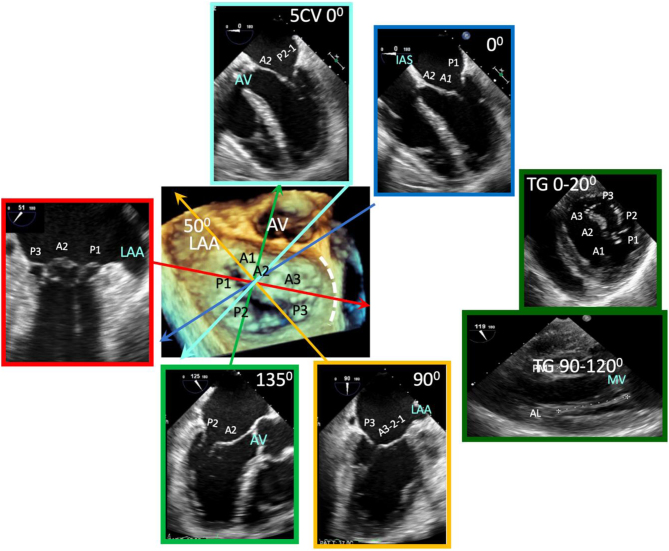
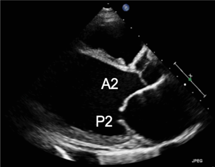
Parasternal long-axis (PLAX): During standard TTE, the mitral valve is first seen in the PLAX window. In this view, the imaging plane is through the centre of the mitral valve, demonstrating A2 of the longer anterior leaflet and P2 of the shorter posterior leaflet (Table 1, images 1 and 5); the postero-medial papillary muscle may be seen extending from the infero-lateral (posterior) LV wall (1, 7). With an inferior tilt of the ultrasound beam (towards the RV inflow and tricuspid valve view), it is possible to image scallops A3/P3 (Table 1, image 7), further tilting will bring into view the postero-medial commissure. A superior tilt of the beam (moving towards the RV outflow and pulmonary view) will demonstrate scallops A1/P1 and eventually the antero-lateral commissure (Table 1, image 6). The anterior and posterior regions of the mitral annulus are also visualised in this view.
Table 1.
MV anatomy and TTE imaging view.
| View | Measure or image | Explanatory note | Image |
|---|---|---|---|
| Parasternal long-axis view (PLAX) |
Image 1
Visual assessment of anatomy and leaflet excursion |
Demonstrate the anatomy and excursion of both mitral leaflets (anterior leaflet leading to the aortic valve, posterior leaflet extending from the base of the infero-lateral wall), the proximal chordae, subvalvular apparatus and annulus anatomy. Imaging in the standard PLAX plane demonstrates MV scallops A2 and P2 (7). Describe leaflet motion: normal, excessive, restricted. |
 |
| Leaflet thickness and calcification | Measure and report leaflet thickness. Describe the extent and distribution of calcification. | ||
|
Image 2
MV leaflet tip M-Mode |
M-Mode can be applied to demonstrate timing and extent of leaflet excursion. |  |
|
|
Image 3
Annular diameter – mid-systole |
Measure the anterior-posterior annular diameter in the PLAX view. Measurements can be made at end-systole or end-diastole. |  |
|
| Image 4 | End-systole is most often used to describe annular size. Measures should be made in mid-diastole when calculating MR volume, 1 frame after the leaflets start to close following early opening (although A4C measures are preferred). Annular dilation should be described in the report. | 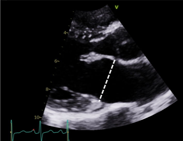 |
|
|
Image 5
2D tilting and multi-plane scanning to view all scallops |
Scallops A2 and P2 are viewed in the standard PLAX view. | 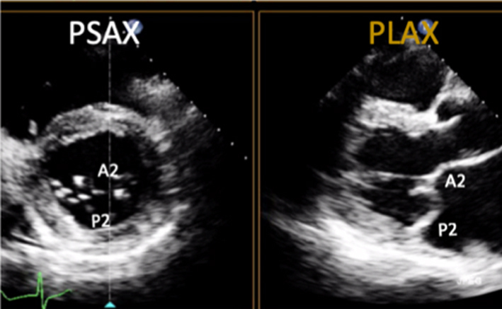 |
|
| Image 6 | Maintaining a focus on the MV leaflet tips while tilting the probe towards the RV inflow view (inferiorly) will demonstrate scallops A3 and P3 and eventually the P-M commissure. | 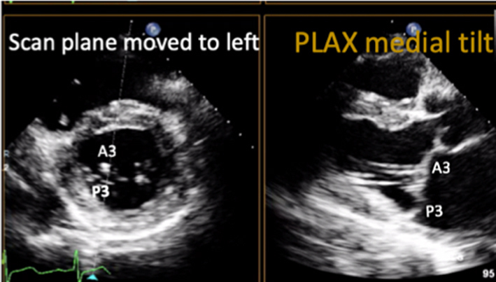 |
|
| Image 7 | Maintaining a focus on the MV leaflet tips and tilting the probe towards the RV outflow view (superiorly) will demonstrate scallops A1 and P1 and eventually the A-L commissure. The same segmental analysis can be performed by primary imaging in the PSAX with a secondary orthogonal plane image orientated to the PLAX view. CFD can be performed at all levels (7). |  |
|
| Parasternal short-axis view (PSAX) |
Image 8
Visual assessment of scallops and commissures |
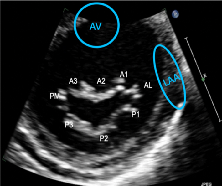
The PSAX imaging plane at the level of the MV is optimised to demonstrate the diastolic excursion of the mitral leaflet tips within the circular LV. Off-axis imaging results in an oblique cross-section imaging plane and oblique view of the leaflets. An off-axis and more longitudinal imaging plane resulting in the LV appearing more elliptic in shape. The ventricular surface of the MV leaflets is visualised in this view with scallops three to one seen from left to right. The PM commissure is adjacent to A3/P3 and the A-L commissure adjacent to A1/P1. Qualitative assessment of leaflet morphology, thickness and excursion is assessed visually. CFD is placed over the MV. Tilting back and forth through the plane of coaptation will demonstrate the regurgitant orifice position (1). |
 |
|
Image 9A 3D imaging: the normal MV viewed from the LA in systole |
3D imaging provides visualisation of the whole valve anatomy and can help identify regurgitant orifice position and size. Adjust the dataset dimensions to include the entire annulus and leaflet tips in both orthogonal viewing planes, ensuring to include the entirety of the non-planar annulus. Optimise the image by adjusting gain and compression. The image can then be orientated into the surgeon's view to demonstrate the atrial surface of the leaflets. | 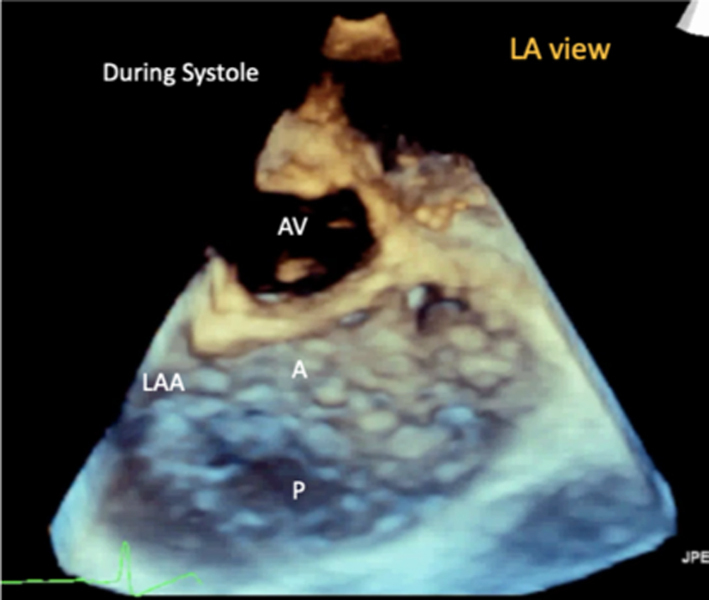 |
|
|
Image 9B 3D imaging: the MV viewed from the LV in diastole |
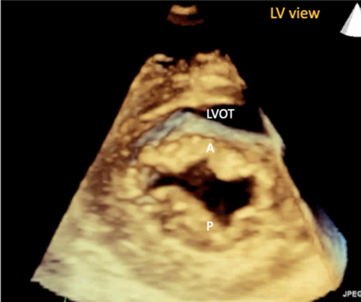 |
||
|
Image 9C 3D imaging: LA view of an abnormal MV demonstrating P2 prolapse |
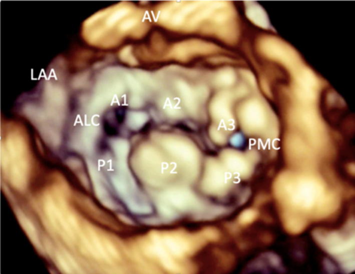 |
||
| PSAX – papillary muscle level |
Image 10
Visual assessment of the papillary muscle |
The postero-medial papillary muscle is seen on the left of the image, the antero-lateral papillary muscle is seen on the right. | 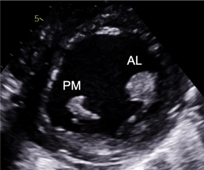 |
| Image 11 | Myxomatous degeneration of the MV may be associated with multiple and diffuse spreading of the papillary muscle and should be reported. | 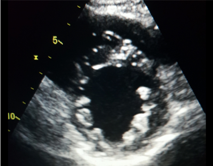 |
|
| Apical four-chamber view (A4C) |
Image 12
Visual assessment of the leaflets and scallops – arrowed line demonstrates the imaging plane of the A4C view |
Assess and describe the anatomy and excursion of both mitral leaflets, describing the location and extent of any excessive or restricted motion. | 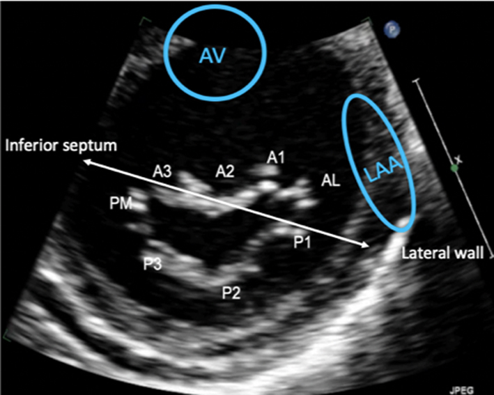 |
| Image 13 | The anterior leaflet is seen closer to septum, the posterior leaflet adjacent to infero-lateral wall. The scallops typically imaged in the A4C view are: A3/A2 and P1. | 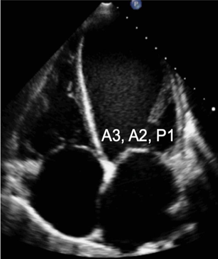 |
|
| Apical two-chamber view (A2C) |
Image 14 Visual assessment of the leaflets and scallops – arrowed line demonstrates the imaging plane of the A2C view |
The A2C view is optimised to demonstrate the inferior and anterior LV walls. | 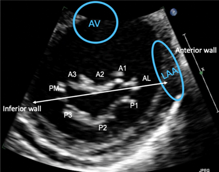 |
| Image 15 | In this view, the MV leaflets are: P3 adjacent to the inferior wall, P1 adjacent to the anterior wall and anatomically inferior to the LAA (superior in the image) with A2 seen in the centre of the valve. | 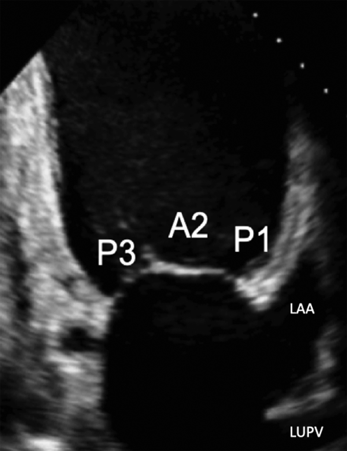 |
|
| A2C view |
Image 16
Commissural diameter measure |
 |
|
| Apical three-chamber view (A2C) |
Image 17 Visual assessment of the leaflets and scallops – arrowed line demonstrates the imaging plane of the A3C view |
The A3C view is optimised to demonstrate the antero-septum and the infero-lateral wall. When achieved, the imaging plane is through the centre of the MV, demonstrating scallops A2 and P2. | 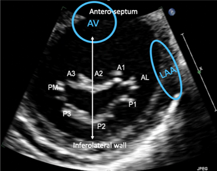 |
| Image 18 | 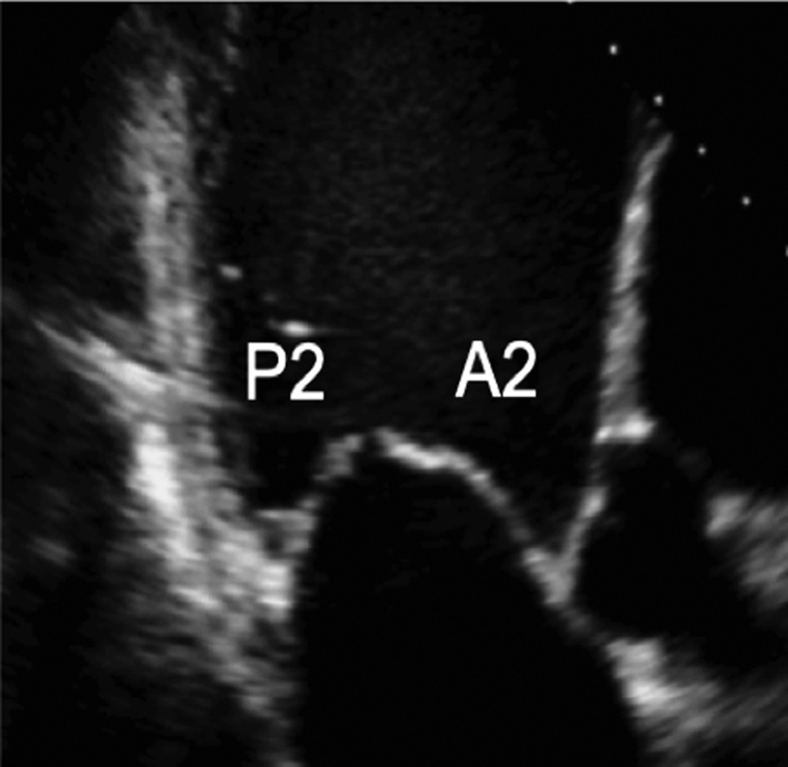 |
Parasternal short-axis (PSAX): Orthogonal to the long-axis plane are the short-axis views of the left heart. At the level of the mitral valve leaflets, the ventricular surface of all scallops and both commissures can be visualised in their entirety (Table 1, image 8). From the level of the valve, tilting inferiorly (towards the apex) will bring into view both papillary muscles (Table 1, image 10). Consistent with the commissures they support, the postero-medial PM is seen on the left and the antero-lateral on the right (7) (Fig. 1).
Apical four chamber (A4C): An oblique plane of the anterior leaflet is seen in the A4C with scallops A3 and A2 seen from left to right, P1 of the posterior leaflet is seen (Table 1, images 12 and 13). In this plane, the antero-medial and postero-lateral regions of the mitral annulus are viewed. The anatomically superior position of the MV annulus relative to the tricuspid annulus (further from the apex) is appreciated best in this view (7). The normal inter-annular offset distance is 5–11 mm. If MV and TV annular planes are seen at the same level or there is an inter-annular distance exceeding 11 mm (8 mm/m2) (8) this may be associated with congenital abnormalities (atrio-ventricular septal defects with a common annular plane, or Ebsteins’ anomaly where the TV is displaced further towards the apex).
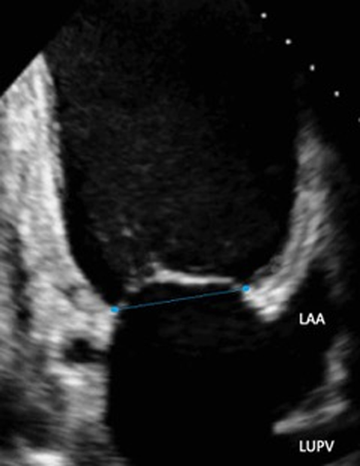
Apical two chamber (A2C): Rotating the probe anti-clockwise until the right heart is no longer imaged demonstrates the A2C view. When scanning in this window, also referred to as the bi-commissural view, the plane of imaging is along the line of leaflet coaptation, such that A2 is seen in the centre of the valve with P3 and P1 seen on the left and right, respectively (Table 1, images 14 and 15). The postero-medial and antero-lateral aspects of the MV annulus are seen (1, 7).
Apical three chamber (A3C): Further rotation brings the central portion of the MV into view. Similar to the PLAX view, A2 and P2 are visualised (Table 1, images 17 and 18).
3D TTE assessment
3D volume assessment
Volumetric datasets acquired during 3D imaging provide visualisation of the valve from any angle or in any plane. Manipulation of the datasets allows for the assessment of the valve from the perspective of the left atrium, demonstrating the specialist view of the MV known as the ‘surgeon's view’ (7). In this view, by displaying the aortic valve at the top centre of the image (12 o’clock) and the left atrial appendage to the left (9 o’clock), scallops one to three are seen from left to right (Table 1, image 9C). The TTE MV datasets can be acquired in either the parasternal or apical views. The parasternal window often provides better 3D image quality of the MV. This is, in part, due to the proximity of the valve to the ultrasound probe, but also due to the superior image resolution of the axial plane over that of the lateral when the valve is closed in systole. However, in this orientation, the MV leaflets are parallel to the scan lines and drop-out may occur, particularly when leaflets are thin. When imaging in the apical window, more scan lines are utilised to image the MV during the cardiac cycle and compensate for the lower azimuthal and elevation resolution. As a result, it may be easier to obtain good quality 3D datasets of the MV from the apical approach. 3D zoom provides superior imaging of the valve in comparison to full-volume and live 3D modalities. Image optimisation is achieved by adjusting the area of interest to include the entire annulus and leaflet tips in both orthogonal viewing planes, ensuring to include the entirety of the non-planar annulus. Although stitching of the dataset over two, four or six beats increases imaging volume (frame) rates (VR) and improves temporal resolution, variable R-R intervals secondary to atrial fibrillation (AF) or respiratory motion can lead to stitching artefact and dyssynchronous motion of the volumes within the dataset (1, 7). Breath-holding may avoid such artefacts.
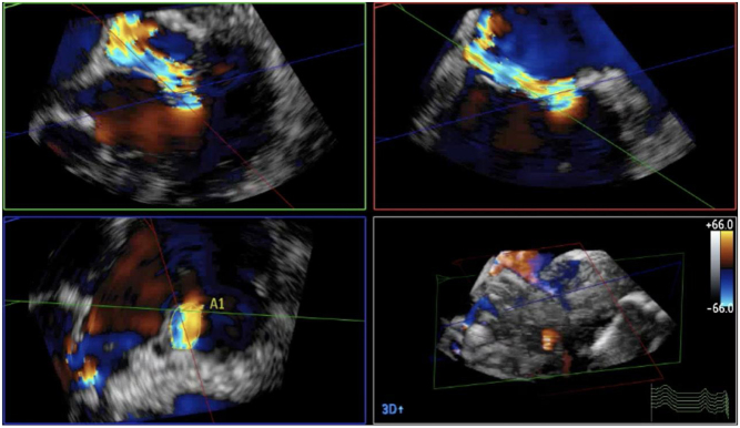
Advances in ultrasound technology have enabled the acquisition of high VR 3D datasets with the addition of colour flow Doppler (CFD), a modality until more recently limited by its reduced temporal resolution of the 3D volumes. By integrating CFD into the 3D dataset, it is possible to identify the 3D proximal isovelocity surface area (PISA) and vena contracta (VC) and permits simultaneous VC measurement in orthogonal planes (1).
3D dataset for orthogonal planes
The matrix arrangement of piezoelectric elements within the head of the 3D probe enables the generation of a conical volume dataset. When creating 3D imaging, all elements within the matrix are utilised to create the volumetric dataset. However, when two perpendicular element lines are activated instantaneously, it is possible to display orthogonal imaging planes simultaneously, providing greater insight into the extent of valvular pathology or improved alignment with valvular anatomy (Table 1, image 5). Simultaneous multi-plane imaging (such as Xplane or Multi-D) provides a second scan plane which initially displays an orthogonal view to the primary (live) imaging plane. The position of the second imaging plane can be adjusted (using rotation or tilt function) to demonstrate a simultaneous view of any anatomy within the primary image (9). Although the imaging planes are usually orthogonal, the second image can be adjusted to any degree of rotation from the primary image. This form of imaging allows visualisation of the MV from the lateral to the medial aspect of the coaptation line (segmental analysis). The MV anatomy, and therefore mechanism of valve failure, can be assessed in detail. Any focal lesions such as prolapse can be located accurately.
Doppler assessment of flow
PISA
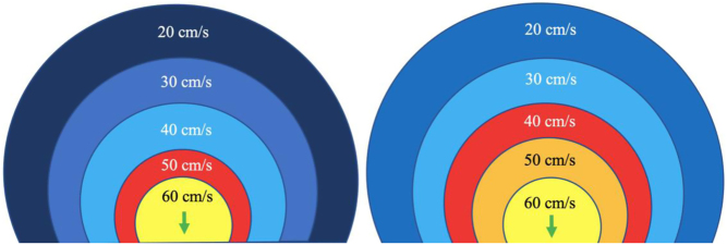
When liquid flows from a large chamber through a smaller orifice at a fixed rate, flow velocity increases to a point at which it is greatest as it converges on the narrowest region of the flow (10). When the orifice is planar, rounded and narrow, this flow convergence occurs in a hemispherical geometry (Fig. 2) with a velocity that is equal throughout the hemisphere surface and is referred to as the proximal isovelocity surface area (PISA). These flow convergence hemispheres are better identified on echo by reducing the CFD velocity at which blood flow aliases (Nyquist limit) to between 20 and 40 cm/s in the direction of the flow. Doing so identifies the hemisphere moving at our selected velocity in the direction of the orifice and allows measurement of the hemisphere height (Fig. 2). Since flow velocity increases as blood approaches the regurgitant orifice, the relationship between PISA radius and Nyquist limit is inverse (PISA height increases as the Nyquist limit is reduced) (1).
Figure 2.
Schematic on the left demonstrates the PISA at a Nyquist limit of 50 cm/s, any velocity exceeding this will alias and be assigned a colour representative for the opposite direction. The schematic on the right demonstrates the PISA at a Nyquist limit of 40 cm/s. This increases the size of the PISA being imaged and improves measurement accuracy (1).
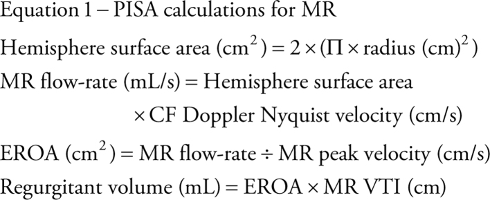
Since the rate of flow throughout the convergent shells and orifice is equal (volume does not alter with changing geometry, only velocity changes), the flow rate through the orifice (mL/s) can be calculated by multiplying the surface area of the hemisphere (2Πr2) by the Nyquist velocity at that point (the alias velocity selected) (11). The orifice area can then be calculated by dividing the flow rate by the velocity of the flow through the valve (equation 1).
 |
Continuity equation
Based on the theory of conservation of mass, the continuity method of estimating flow volumes can provide estimates of both mitral valve area (MVA) and regurgitant volume (11). The theory of conservation of mass assumes that in a closed hydraulic system, the volume of flow through two regions is equal and that any change in velocity, and therefore reflected in the flow VTI, between the two sites, is determined by differences in anatomy between them.
-
For MVA
When applying the continuity equation to estimate MVA, the left heart stroke volume (SV) is calculated at the site of the left ventricular outflow tract (LVOT) by multiplying the LVOT cross-sectional area (CSA) by the LVOT VTI (equation 2).
 |
Assuming SV is the same through both the LVOT and MV orifice, the equation can be rearranged and the MVA can be calculated (12) as:
 |
-
For MR volume
When both mitral and aortic valve function is normal, the SV leaving the LV through the LVOT is the same volume of blood that enters the LV through the MV. However, when MR is present, the trans-mitral SV in diastole is greater than the SV through the LVOT in systole (due to the normal filling volume combined with returning regurgitant volume from the previous systolic cycle). On this assumption, the presence of MR will result in a greater SV through the MV in diastole in comparison to through the LVOT in systole, the difference being the volume of MR (12).
 |
Pressure half-time
As described previously, when blood flows across a stenotic valve in a normal flow state (normal SV and normal ejection time), the velocity of flow is determined by the pressure difference across the narrowed valve, which in turn is determined by the degree of stenosis (1). Furthermore, in addition to pressure gradient and maximum velocity of flow, the degree of stenosis will also affect the time it takes for pressures on either side of the stenosis to equalise and for the blood flow velocity to fall by half the starting value (P½t). When the valve opens fully, the volume and rate of flow across the valve remain normal. In this normal state, the rapid flow of volume across the valve results in rapid equalisation of pressure on either side of the valve (the transfer of volume causes a fall in pressure within the chamber it exits (LA) and an increase in pressure within the chamber it enters (LV), to the point that pressures eventually equalise). Since pressure differences determine the velocity of blood flow, a rapid fall in pressure difference will result in a rapid fall in blood flow velocity. This is reflected by a very short time for the trans-mitral blood flow velocity to fall by half the starting value, resulting in a steep E wave deceleration slope. Conversely, when stenosis is severe and valve opening is significantly restricted, the volume of flow across the valve is reduced, leading to reduced filling of the LV and consequently low LV diastolic filling pressures. Simultaneously, the reduction of flow across the MV prevents adequate emptying of the LA, with consequent volume and therefore pressure overload, a significant diastolic pressure difference between the LA and LV is therefore maintained. Because high-pressure difference is maintained throughout diastole, the time taken for the pressure difference to fall by half its value is extended (1, 13). This is reflected by continually high trans-mitral flow velocity throughout diastole and therefore a shallow E wave deceleration slope. Therefore, the rate of pressure decay (and thus the rate at which blood flow velocity falls) is considered reflective of the degree of valve opening and inversely proportional to the valve area (13). It is on this basis that estimates of P½t can be utilised to estimate MVA.
When assessing mitral stenosis, the rate of pressure decay can be measured and utilised to calculate valve area (equation 5) where 220 is a constant that is proportional to the assumed net compliance of the LA and LV. MVA can then be calculated (13) by:
 |
Pressure gradient
As mentioned previously, the flow of blood through the circulatory system relies on the existence of pressure differentials between two regions, the direction and velocity of flow being determined the magnitude of pressure difference between them (1). When a narrowing occurs along the path of flow, pressure builds prior to the obstruction creating a pressure gradient across it that increases as the narrowing worsens. As flow velocity is determined by pressure differences (velocity increases as the pressure difference increases), progressive narrowing of anatomy will lead to a gradual increase in the pressure gradient and therefore flow velocity through the narrowed region. Because echocardiography measures the velocity of blood flow through the heart, not the pressure difference driving the flow, the simplified Bernoulli equation is applied to calculate pressure difference from the measured velocity (14) (equation 6):
 |
This notion can be applied to the assessment of the stenotic mitral valve, where mild stenosis is associated with a small pressure gradient and low velocity flow across the valve while severe stenosis results in a high transvalvular pressure gradient and high blood flow velocity.
Vena contracta
The vena contracta is the narrowest region of the regurgitant jet as it flows into the LA. It occurs immediately downstream of the regurgitant orifice and is slightly smaller in CSA than the anatomical regurgitant orifice (15, 16). Although the VC measured by CFD is influenced by loading conditions and flow rate due to incorporation of blood mass already within the LA, the VC remains an effective measure of regurgitant orifice area and therefore MR severity, with particular strength in eccentric jets.
Mitral regurgitation
Aetiology and mechanism
Mitral regurgitation is the most common valvular abnormality in developed countries and is the second most frequent indication for valve surgery in Europe (17). MR can be broadly categorised as either primary, with intrinsic abnormalities of the leaflet and/or subvalvular apparatus, or secondary (functional) when MV anatomy is normal but abnormalities of the LV and/or LA disrupt normal valvular function (1, 12).
It is important to define the underlying aetiology of MR since the disease type informs management. For example, mitral valve prolapse typically results in valve repair (17), whereas secondary ischaemic MR will first require heart failure optimisation with optimal medical therapy, which may include cardiac resynchronisation therapy and possibly transcatheter intervention (18). The commonest causes of moderate or severe MR include degenerative disease (also referred to as mitral valve prolapse (MVP)) accounting for around 60%, rheumatic valve disease seen in 15% and secondary MR responsible for approximately 20% of all cases (1). A particular aetiology may result in a combination of mechanistic failures (Fig. 3).
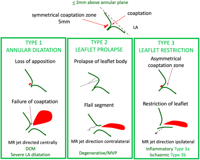
Figure 3.
Mechanism of MR is described in terms of leaflet motion. The top diagram depicts normal leaflet function in systole in a competent mitral valve. Carpentier’s classification categorises this concept into three types. Type 1: normal leaflet motion with annular dilatation and increasing loss of coaptation as the two leaflets are pulled apart. Type 2: excessive leaflet motion where there is prolapse of redundant tissue above the level of the MV annulus into the LA, or when, due to the loss of primary chordal support, the tip of the leaflet everts and ‘points’ into the left atrium, called flail. Type 3 describes reduced leaflet motion, termed leaflet restriction. This can be due to primary leaflet disease where the leaflet is shortened due to retraction, in turn restricting excursion during the cardiac cycle. This restriction of motion prevents the leaflets from forming an adequate coapation height (tissue overlap). This is categorised as type 3a. Type 3b describes leaflets that are anatomically normal, but that are tethered due to a disease of the left ventricle. The left ventricle is dilated and or there are underlying wall motion abnormalities effecting papillary muscle function resulting in increased tension on the subvalvular apparatus. This in turn leads to tethering of the leaflets into the LV and prevents their return towards the annular plane to meet the opposite leaflet in systole, with resultant mitral regurgitation (1).
An understanding of the mechanism of valve failure is critical in determining patient selection for suitability of valve intervention, including repair. However, it should be noted that an appreciation of the anatomical abnormalities additionally ensures that the extent and severity of the MV lesions are not underestimated. The mechanism is defined according to leaflet motion using Carpentier’s classification (19) (Table 2) and can be: normal, MR results from isolated annular dilatation (either from LA or LV dilatation) or leaflet perforation (type 1); excessive, MR results from leaflet prolapse (type 2); or restricted, MR can be due to leaflet restriction and retraction (type 3a) or LV remodelling with underlying wall motion abnormalities (type 3b). Additionally, the MR jet direction lends important clues to the underlying mechanism of valve failure and their potential aetiologies (Table 3). A flail segment from chordal rupture or identification of complete loss of coaptation with a visible coaptation gap are two specific mechanisms indicative of severe valve regurgitation, see echo descriptors below for details of definitions.
Table 2.
Carpentier’s classification.
| Type 1 – Normal leaflet motion |
| The predominant cause of type 1 MR is annular dilation. Although this is more commonly due to LV dilatation, significant LA dilatation is also increasingly recognised as an underlying cause (typically associated with atrial fibrillation). However, in rare cases, type 1 MR may be caused by a leaflet perforation secondary to either infective endocarditis or an iatrogenic complication of cardiac surgery. |
| Type 2 MR – Excessive leaflet motion |
| Type 2 MR occurs secondary to leaflet prolapse. Severe MR secondary to papillary muscle rupture may be a mechanical complication following myocardial infarction (MI) and is a rare cause of type 2 MR. |
| Type 3 – Restricted leaflet motion |
| Type 3 MR is sub-divided into two categories: leaflet restriction during both systole and diastole (type 3a) and leaflet restriction during systole only (type 3b). Type 3a is more frequently secondary to leaflet thickening and fusion. Although typically rheumatic in aetiology, post-inflammatory thickening and post-radiotherapy fibrosis are also recognised aetiologies. Type 3b occurs when the mitral leaflets are structurally normal but underlying LV disease results in leaflet tethering into LV and, consequently, leaflet restriction (typically seen in ischaemia of the infero-lateral wall with asymmetric systolic tethering of the posterior leaflet, Fig. 3). It may also be seen when global LV dilation results in symmetric bileaflet tethering and reduced coaptation (Fig. 3). |
Table 3.
Mechanisms and jet direction.
| Mechanism of central jets |
| – Annular dilation and reduced leaflet coaptation through LA enlargement, most often caused by atrial fibrillation. Usually associated with reduced coaptation height and leaflet flattening in systole. – Central jets are also seen when LV dilation leads to symmetric leaflet tethering and increased coaptation height. |
| Mechanism of posteriorly directed jets |
| – Anterior leaflet prolapse and or flail causes simple override of the anterior leaflet directing the regurgitant jet in the opposite direction. – Ischaemic MR occurs when papillary muscle dysfunction leads to tethering of the posterior leaflet. This inhibits the posterior leaflet from returning to a normal systolic closure position and results in the anterior leaflet coapting with the body of the posterior leaflet rather than the tip. This creates a mechanism of pseudo-prolapse that directs the jet in the direction of the lesion, in this case posteriorly. – Systolic distortion of the leaflets secondary to the systolic anterior motion of the AMVL. |
| Anteriorly directed jet |
| – Posterior leaflet prolapse and or flail causes simple override of the anterior leaflet directing the regurgitant jet in the opposite direction. |
| Leaflet perforation |
| – The direction of MR jets due to leaflet perforation depends upon the site of the regurgitant orifice. – The anterior leaflet base is the most common site of iatrogenic perforation. Assessment post-MV repair should ensure that the CFD box includes the whole annular ring. |
Grading mitral regurgitation severity
The degree of mitral regurgitation is heavily influenced by variations in heart rate and blood pressure (20). It is therefore essential that these parameters are documented in each report and considered when comparing serial echo findings (Table 4). In addition, height, weight and body surface area should always be recorded. Values indexed to patient size provide background context to the absolute dimensions and parameters of LA and LV volume and provide important prognostic information (see the 'Haemodynamic consequences' section for details).
Table 4.
Grading MR severity.
| Method | Mild | Moderate | Severe |
| 2D assessment of MV anatomy | Mild anatomical abnormality of the MV | Moderate leaflet tenting, thickening or calcification | Flail leaflet segment, clear coaptation defect on 2D or 3D echo, papillary muscle rupture/avulsion, large leaflet perforation, marked leaflet retraction |
| LA size | Normal (may dilate secondary to MS or moderate+ diastolic dysfunction) | Normal or mildly dilated | Always dilated |
| LV size | Not dilated secondary to MR | Normal or mildly dilated | Eventually becomes dilated |
| Jet area | Small jet with low area. Typically narrow, frequently brief and end-systolic | Large central jet that encompasses >50% LA area. Wall adhering jet (Coanda effect) that reaches the upper LA or is seen to wrap around the roof of the LA | |
| Flow convergence | Not seen, brief or small | Intermediate size or non-holosystolic | Large and holo-systolic |
| CW Doppler | Faint/partial/parabolic | Dense but partial/parabolic | Density similar to forward flow signal/triangular (when acute severe or torrential) |
| Vena contracta (cm) | <0.3 | Single plane <0.3–≥0.69 Biplane 0.31–≥0.79 |
Single plane ≥0.7 Biplane ≥0.8 cm |
| Pulmonary vein flow | S dominant (may be blunted in AF or diastolic dysfunction) | S dominant but may be blunted if eccentric MR (may be blunted in AF or diastolic dysfunction) | S flow reversal |
| Mitral forward flow | A dominance (E may be dominant in the young or moderate+ diastolic dysfunction) | Variable | E wave dominant (E velocity >1.5 m/s) |
| EROA (cm2) | <0.2 | 0.2–0.39 | ≥0.4 (may be lower in secondary MR or when EROA is elliptic) |
| Regurgitant volume (mL) | <30 | 31–59 | ≥60 (may be lower in secondary MR or when EROA is elliptic) |
| Regurgitant fraction (%) | <30% | 30–49% | >50% |
Data from the ASE table for grading the severity of chronic MR by echocardiography (15).
Key anatomical findings
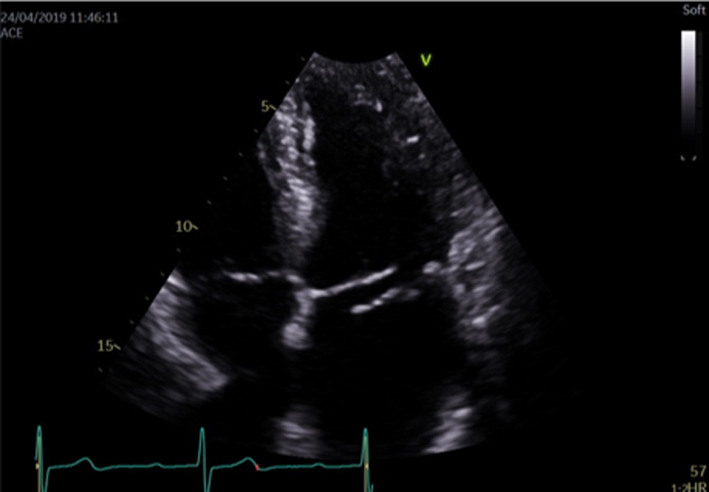
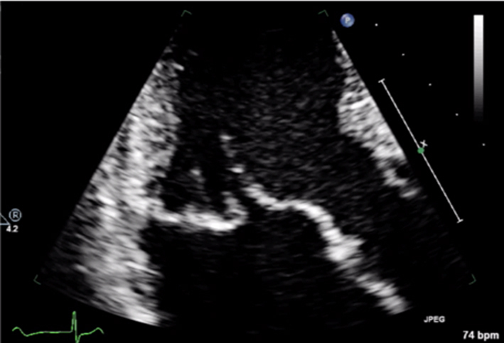
Although MR severity cannot be quantified by the appearance of anatomy alone, certain anatomical characteristics are associated with severe MR. A flail leaflet segment (eversion of the leaflet tip into the LA) identifies a major coaptation defect and is associated with severe regurgitation (1). Similarly, frank loss of leaflet coaptation (also referred to as coaptation gap) denotes a large regurgitant orifice and the presence of severe MR (Table 5, images 1, 2, 3).
Table 5.
Guide to 2D image acquisition in mitral regurgitation
| View | Measure or image | Explanatory note | Image |
|---|---|---|---|
| All views |
Image 1
2D anatomy that is suggestive of severe MR |
Report a flail leaflet, scallop or leaflet tip if part of the leaflet points towards the upper left atrium in systole (eversion). | 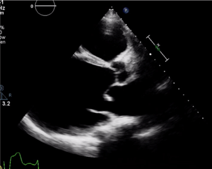 |
|
Image 2 Coaptation defect |
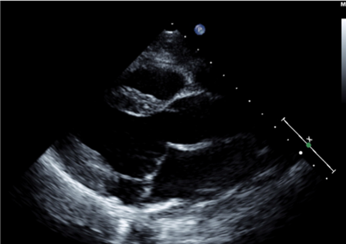
Describe clear coaptation defects and the location. Comment on which leaflet is affected, how extensive and which scallop. There will be severe regurgitation. Assess both papillary muscles and chordae for ruptures. To review the subvalvular apparatus, use all views available Report related findings according to suspected clinical aetiology, for example, regional wall motion abnormalities and left ventricle function in myocardial infarction, vegetations in endocarditis. Report MAD when seen. |
 |
|
|
Image 3 Coaptation defect |
 |
||
|
Image 4 Mitral annular disjunction |
 |
||
| All views |
Image 5 CFD PLAX |
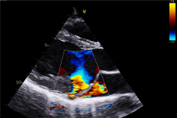
Optimise CFD settings (see BSE Minimum Dataset (7)). Adjust the lateral CFD Region of Interest (ROI) to include 1 cm of the LV on the left lateral border and the roof of the LA on the right lateral border (7). The CFD ROI height should not extend beyond the anterior and posterior LA walls. Simultaneous MV and AV CFD assessment should not be performed. Eccentric jet PISA should be measured in the view that the greatest radius is seen |  |
|
Image 6 PLAX PISA |
 |
||
| PSAX |
Image 7
CFD MV leaflet tips level |
Apply CFD to the short-axis view of the MV to identify the location and extent of the regurgitant orifice along leaflet coaptation | 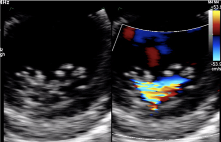 |
| All apical views |
Image 8
CFD assessment of MR |
Ensure that the CFD box is optimised to demonstrate the whole MR jet, but that temporal resolution is maintained by not extending the CFD box beyond what is required to view the regurgitant jet. Describe the jet characteristics: direction, width, how far it extends into the LA. | 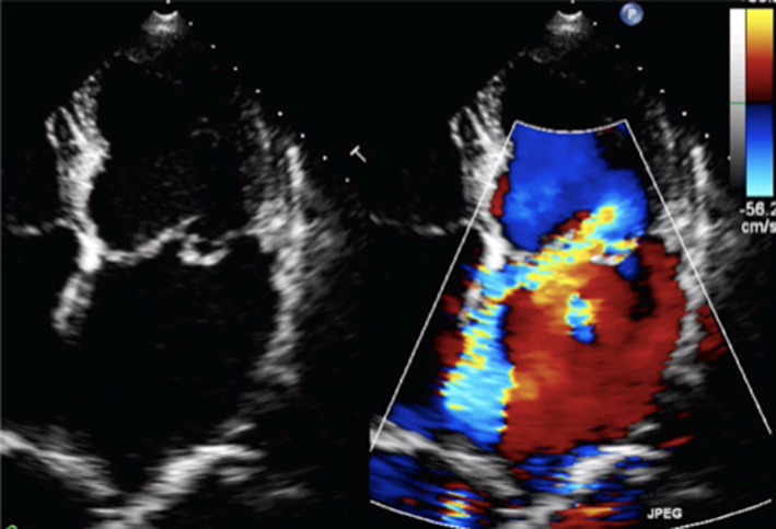 |
|
Image 9
MR CFD |
Calculate jet area by tracing both the MR jet and the LA area. Jet area >50% of LA area suggests severe MR | 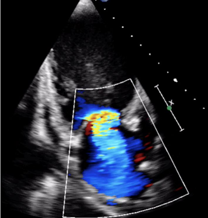 |
|
|
Image 10
MR jet area |
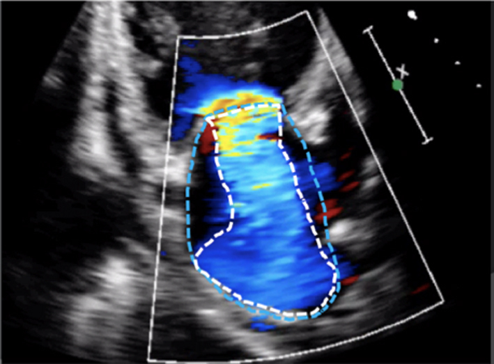 |
||
| All views |
Image 11
MR CW |
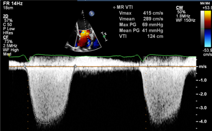
Assess CW density for a qualitative assessment of MR Place the cursor through the PISA and VC. Enter CW mode and optimise, ensuring that the full MR signal is visualised below the baseline and that the forward flow signal is visible above the baseline. A faint CW Doppler signal is suggestive of trace-mild MR; CW signal density increases as MR becomes more severe such that severe MR CW is of similar density to the diastolic forward flow density (33). Limitation: Poor alignment with eccentric jets can lead to incomplete spectral Doppler signals or discrepant signal density for the degree of regurgitation. |
 |
| Image 12 | Report density and signal waveform, including shape (triangular vs parabolar) and pre-systolic components | 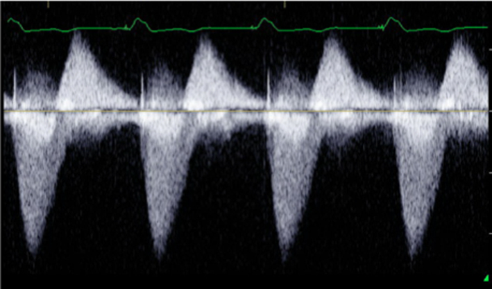 |
|
|
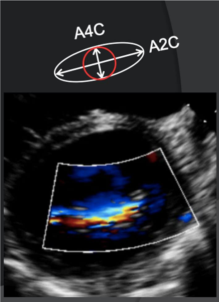
Image 13 How to measure vena contracta |
 |
||
|
Image 14 A4C VC measure |
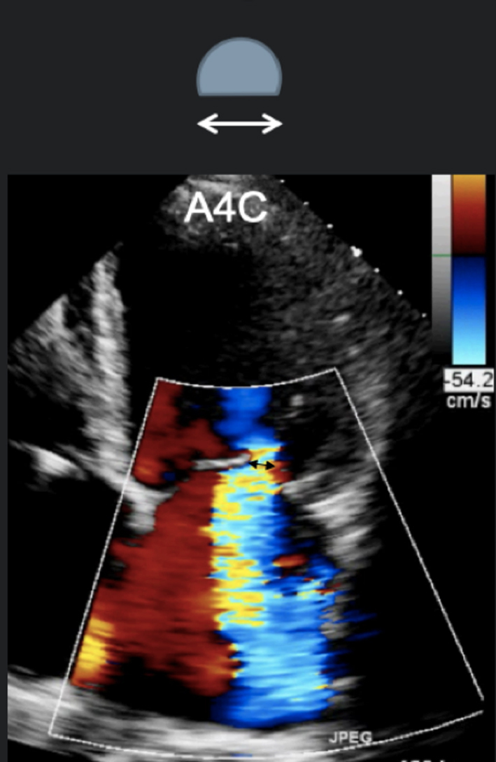
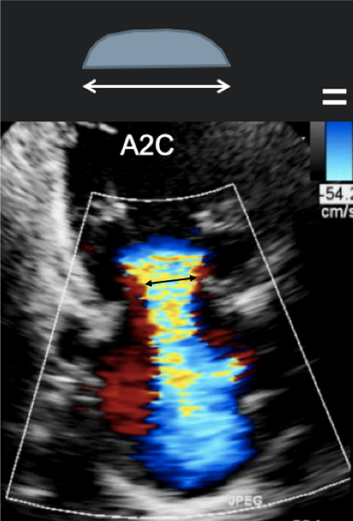
Obtain a clear view of the colour flow through the mitral valve in PLAX, A4C or A2C viewsIf necessary, scan along the commissural line to identify the regurgitant orifice and that the PISA, VC and jet expansion are demonstrated. Zoom in on the colour flow through the mitral valve. Record a loop and scroll through to identify the image with maximal flow through the valve. The VC is the narrowest region of the regurgitant jet (usually just above the valve in the left atrium). Report the average diameter. Single plane diameter ≥0.7 cm or biplane ≥0.8 cm suggests severe MR. Limitations of VC: This method is simple and thought to be independent of haemodynamics, driving pressure, and flow rate. However, low colour gain, poor acoustic windows, and inability to assess multiple jets can underestimate the VC. A high colour gain, irregular shape of jet, or atrial fibrillation can lead to overestimation |
 |
|
|
Image 15
A2C VC |
 |
||
|
Image 16
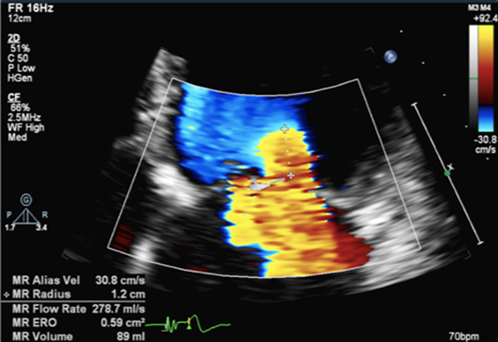
PISA measures for MR |
Zoom on the mitral valve and apply CFD. Reduce the Nyquist limit to between 20 and 40 cm/s (tip: a lower Nyquist limit is more obvious when returning to normal CFD assessment and avoids acquiring the remainder of the study at a lower alias velocity). Once the PISA is clearly seen, gently tilt the probe back and forth to scan through the PISA and identify the greatest radius. Freeze and scroll through the image to the point of the greatest radius, bearing in mind that the PISA radius can be dynamic according to mechanism. |
 |
|
|
Image 17 PISA measure in modified PLAX |
Measure from the leaflet tips to the maximum PISA height (tip: once the height has been measured, supress CFD from the image to ensure that the PISAr measure is from the leaflet surface. Alternatively, utilse colour compare/simultaneous CFD and 2D imaging. | 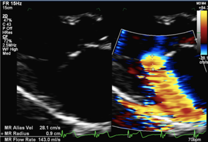 |
|
|
Image 18
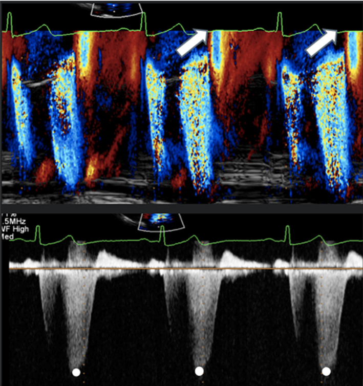
CF M-Mode to identify dynamic PISAr. CW Doppler demonstrating late systolic MR |
Once the radius has been measured, unfreeze the image and place the cursor through the centre of the orifice (tip: place the cursor through the highest PISA radius and VC). Enter CW mode and optimise the signal according to the guidance above. |
 |
|
|
Image 19
End systolic CW trace |
Trace the MR signal. Aim to measure the MR CW signal during a similar R-R as that of PISA measure. | 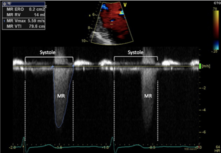 |
|
|
Image 20
CFD M-Mode late systolic MR |
Early or late systolic MR jets should be traced accordingly. Estimate of EROA alone, by measuring just MR Vmax, is not recommended in this scenario and can lead to overestimation of MR severity | 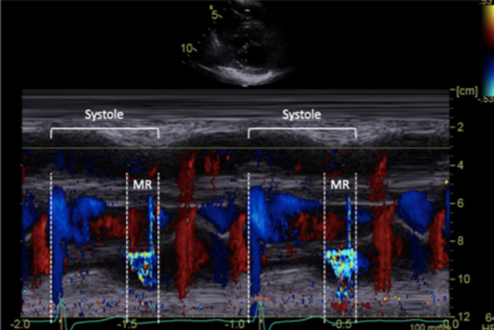 |
|
|
Image 21
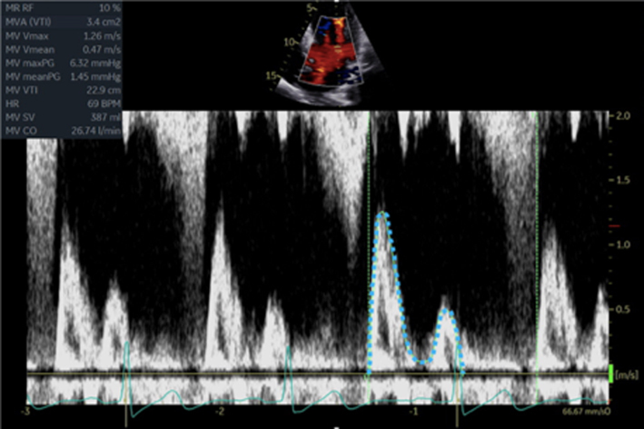
Continuity for MR |
Calculate the LV SV at the level of the LVOT according to the guidance above. Zoom on the MV in the A4C view and apply CFD. Place the cursor at the leaflet tips and enter PW mode. Optimise the PW signal. Freeze the image and trace the Doppler signal. |
 |
|
| Image 22 | Zoom on the MV in the A4C view, ensure that the full annular diameter is included in the image. Freeze the image. Scroll to a point in early- to mid-diastole, measure the annular diameter. |
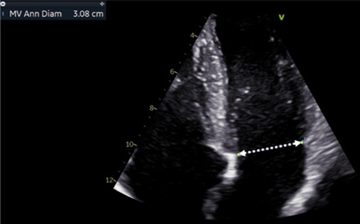 |
|
| Image 23 | Perform the continuity assessment of calculating SV at both sites. Subtract the LVOT SV from the MV SV, the difference is the estimation of regurgitant volume (limitations apply, see the ‘Continuity equation’ section) |
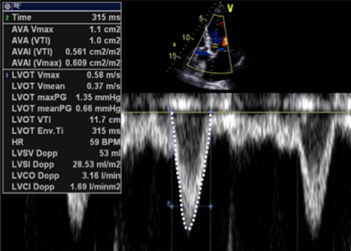 |
|
|
Image 24
Transmitral flow velocity |
Place sample volume (1–3 mm) at level of the MV leaflet tips in diastole. Use of CFD can help to align with the centre of trans-mitral flow. Measure at end expiration Emax: peak velocity in early diastole Amax: peak velocity in late diastole (after P wave) DT: Flow deceleration time from peak E wave to end of E wave signal (25). E wave > 1.5 m/s is suggestive of severe MR in the absence of high-flow states and MS. An E/A ratio < 1 is nearly certainly indicative of non-severe MR. |
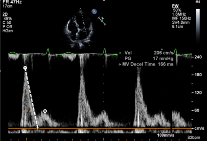 |
|
|
Image 25
PV flow reversal |
Superior angulation of transducer and use of CFD can help locate the pulmonary veins. The right lower pulmonary vein (RLPV) is most likely adjacent to the atrial septum in the A4C view, with the right upper pulmonary vein likely to be visualised in the A5C view (39). | 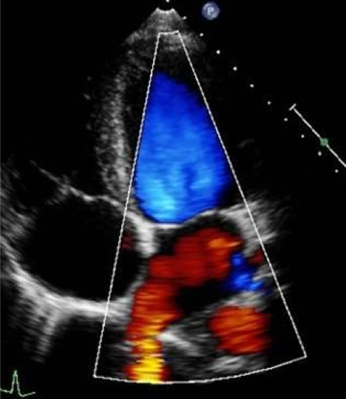 |
|
|
Image 26
Pulmonary vein flow |
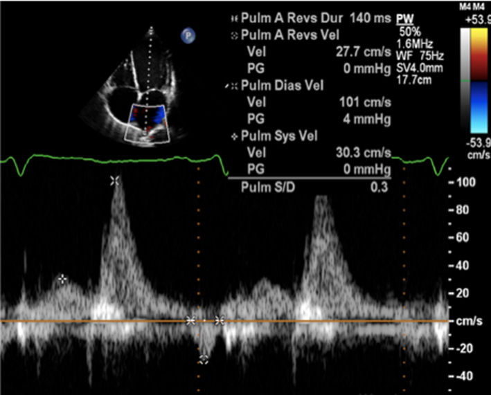
Place sample volume (1–3 mm) 1–2 cm into the vein. Use fast sweep speed (50–100 mm/s). Measure at end expiration. PulV S: peak velocity in early systole (after QRS) PulV D: Peak velocity in early diastole. |
 |
|
|
Image 27
Flow reversal in pulmonary vein |
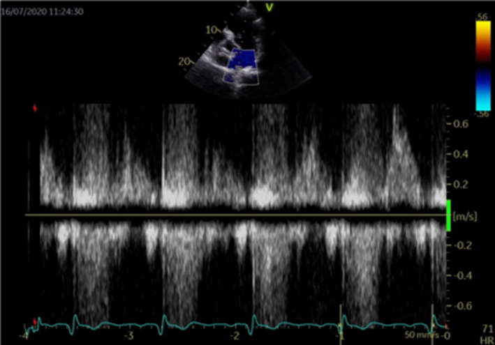
Report systolic flow reversal or blunted S wave. Limitations: any pathology that increases left atrial pressure can blunt PulV flow, LV diastolic dysfunction should be excluded before PV flow is reported. Because PulV S flow reversal has low sensitivity for identifying severe regurgitation, its absence does not exclude severe MR. |
 |
|
|
Image 28A LV size and systolic function |
Simpsons biplane method of discs should be used routinely to assess LV size and LVEF. | 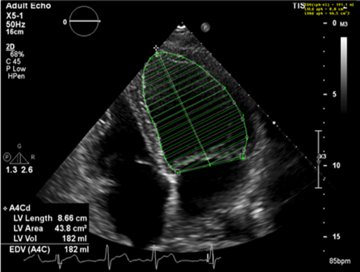 |
|
| Image 28B | 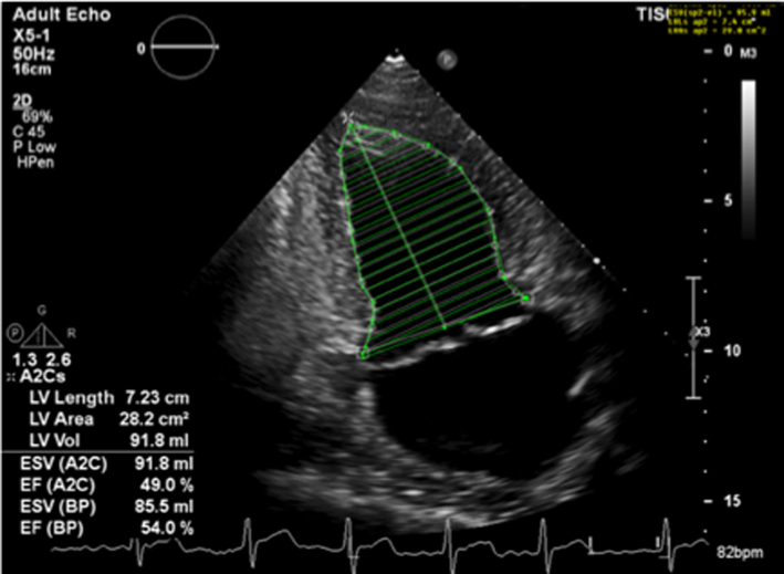 |
||
| Image 29 | Due to the superior accuracy of volume estimation, 3D LV volume and EF is recommended for serial assessment of MR. | 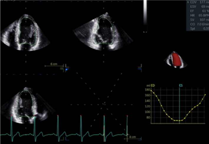 |
|
| Image 30 | Strain may be helpful in identifying subclinical LV dysfunction in the setting of serial echocardiograms and may help determine appropriate follow-up intervals or timing for intervention. | 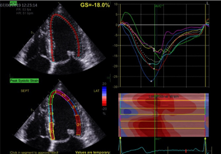 |
|
| A4C and A2C |
Image 31
LA volume |
Biplane LA volume should be estimated using 2D imaging from the A4C and A2C views. As the long-axis dimensions of the LV and LA lie in different imaging planes, the standard apical views optimised for LV assessment do not demonstrate the maximal LA volume. The A4C and A2C images acquired for LA measurement should therefore be optimised to demonstrate the maximal LA length and volume at end-systole. Measurement is made using Simpson’s biplane method and according to the BSE Minimum Dataset (7). However, due to the superior reproducibility and without the need for geometric assumptions, 3D volume measures of the LA are recommended where possible. | 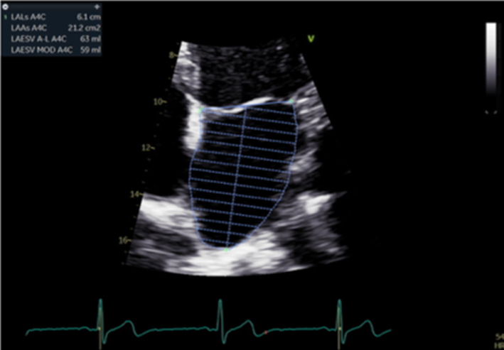 |
| Image 32 | 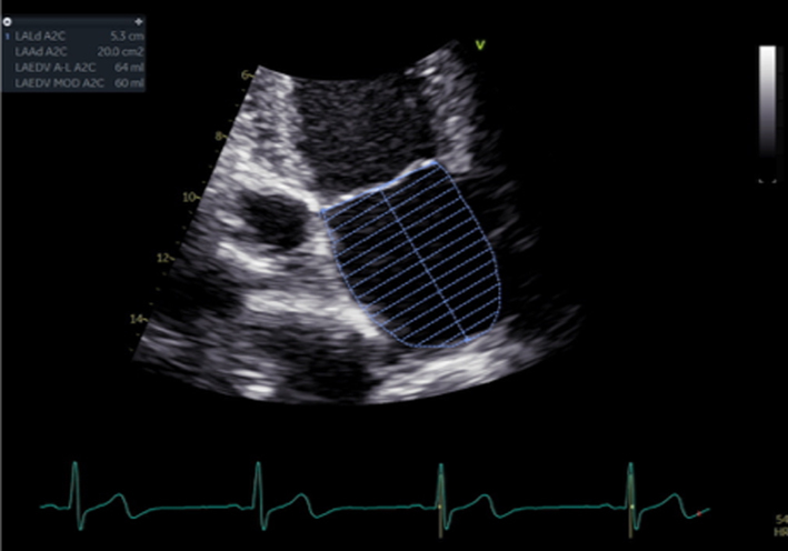 |
||
|
Image 33
Peak TR velocity |
Estimates of SPAP are important for timing MV intervention. | 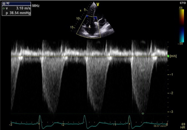 |
Qualitative parameters
Colour flow Doppler (jet area and direction as indicator of mechanism)
Colour flow Doppler (CFD) allows both qualitative and quantitative assessment of the MR severity and helps identify the regurgitant mechanism. When investigating MR by CFD, the regurgitant jet should be assessed in all available views, both on-axis and off-axis, to gain a full appreciation of jet origin, size and PISA (Table 5, images 5, 6, 7, 8, 9, 10). It is recommended that multiple acquisitions are made by slowly rotating between the A4C view and the A3C view while keeping the MR jet in focus.In doing so, it is possible to identify the three regions of the regurgitant jet (Fig. 4): flow convergence on the ventricular surface of the leaflets (PISA), the narrower portion/neck of the jet as it transverses the regurgitant orifice (vena contracta) and the jet expansion within the LA.
Figure 4.
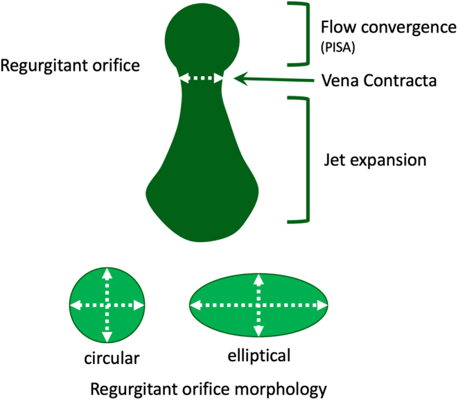
Diagrammatic illustration of regurgitant jet morphology. The three jet components are shown: flow convergence, vena contracta (narrowest portion of the jet as it enters the regurgitant orifice and is just distal to the true anatomic orifice), jet expansion into the receiving chamber (1).
The initial identification of MR and basic evaluation of severity is based on the visual interpretation of jet size by colour flow Doppler (21); the principle being that greater MR severity results in a larger jet within the LA (Table 5, images 5, 6, 7, 8, 9, 10). However, this method requires a qualitative interpretation of MR appearance and is therefore subject to intra and inter-observer variation. A semi-quantitative analysis of MR CFD can be performed by tracing the CFD signal within the LA (jet area) and can be used as a stand-alone indicator of MR severity. When combined with LA size measurement, the percentage of LA area the MR jet fills can also be calculated (21). A value > 50% is suggestive of severe MR (21) (Table 5, image 10). It is important to note that the Nyquist limit should be set to a range of 50–60 cm/s and colour gain optimised when assessing blood flow.
However, these methods are limited by a number of technical and haemodynamic factors that influence the CFD jet appearance and size (22). For a given MR severity, unoptimised scan settings (Nyquist limit outside of the 50–60 cm/s range or unadjusted colour gain) will lead to over or underestimation of MR severity. Low driving force (low SBP) and therefore reduced MR volume, increases in LA pressure (LAP) through mitral stenosis (MS) or LV diastolic dysfunction, increases in LA size, and jets that adhere to the LA wall due to Coanda effect will all result in varying degrees of underestimation of MR severity (22). Therefore, although CFD should be used to identify the presence of MR, it should not be used in isolation to quantify severity (1, 22). However, by identifying the origin and direction of MR, CFD is crucial in distinguishing the mechanism of regurgitation (Table 3).
3D TTE provides an instantaneous assessment of all segments of each leaflet, the commissures and the annulus. The MV can be viewed in real-time from the surgeon’s perspective (‘surgeon's view’) within the LA (Table 1, image 9). The location of lesion(s), site of regurgitation (3D colour) and extent of disease can be rapidly appreciated. 3D colour flow Doppler mapping of mitral regurgitation allows the regurgitant jet to be assessed in all planes and is particularly useful in the analysis of eccentric mitral regurgitation or the visualisation of multiple jets (23). In addition, because 3D echocardiography provides a live assessment of the whole MV anatomy and function from the atrial perspective, a great advantage of 3DE, compared to either the anatomist or the surgeon’s view, is the ability to assess in real-time the functional anatomy of the valve within the beating heart, this is particularly useful in the assessment of primary MR.
Continuous wave Doppler (waveform density and late systolic MR)
The density and velocity of the CW Doppler signal can also be used as a qualitative guide to MR severity. Because CW signal density is proportional to the number of blood cells within the region of sampling, dense signals are suggestive of more severe MR, while faint signals are suggestive of mild regurgitation (24). Additionally, because of rapid pressure equalisation, a triangular waveform with peaking in early systole is suggestive of very severe or torrential, often acute MR (1, 12) (Table 5, images 11, 12).
Under normal circumstances and with normal systolic blood pressure, MR velocity is high, usually reaching 5–6 m/s. Low MR velocity is therefore suggestive of reduced SBP (potentially a sign of decompensation in severe MR) or high left atrial pressure and a reduced pressure difference between the LV and LA, often indicative of severe MR (25).
Quantitative assessment of MR
Vena contracta
As MR flows from the area of convergence within the LV (PISA), through the valve and into the LA, it narrows at a point within the LA immediately superior to the regurgitant orifice; this region is described as the vena contracta (VC) (Fig. 4). The VC is reflective of the regurgitant orifice area and can be measured as an indicator of MR severity. When performed during TTE, it should be measured in any view where the three components of the regurgitant jet are seen (Fig. 4; Table 5, image 14). The principle of VC measurement assumes that the regurgitant orifice is of circular geometry with a similar diameter in orthogonal planes (1). However, the regurgitant orifice geometry in secondary MR is typically elliptical (12), the profile being narrower in the A4C view and wider in the A2C view due to the orientation of the leaflet coaptation plane (Table 5, images 14, 15). Measurement should therefore be averaged from near-orthogonal planes, usually the A4C and A2C views, and should be averaged over two to three beats. As a direct measure of effective regurgitant orifice geometry, the assessment of VC is particularly useful for the assessment of eccentric MR jets when other methods of grading severity are less accurate. An average VC < 3 mm suggests mild MR while a VC > 8 mm is consistent with severe MR irrespective of aetiology (15); > 7 mm is suggestive of severe MR when VC is measured in a single plane. Because of the near-orthogonal measurement planes, accurate depiction and careful measurement of the vena contracta (both 2D and 3D) will avoid the risk of MR underestimation when the regurgitant orifice is non-circular. Therefore, the routine use of VC (averaged between A4C and A2C) is encouraged in secondary MR quantification (15).
However, limitations of VC exist. When measured in the PLAX, imaging must be optimised to ensure perpendicular alignment with the regurgitant orifice to allow accurate measure of the VC. Furthermore, since multiple measurements cannot be combined to estimate overall MR severity, the VC estimation is limited when multiple jets are present. As described previously, overall severity is overestimated when MR occurs in late systole only. If available, the use of 3D echo formats such as biplane imaging to assess the VC in simultaneous orthogonal or semi-orthogonal views or 3D zoom CFD can aid in identifying the regurgitant orifice morphology (15).
While prognostic data is lacking, the 3D vena contracta area is increasingly utilised and, when combined with Doppler parameters, may better define the EROA and regurgitant volume, avoiding underestimation. The threshold for severe MR has been defined as > 40mm2 (20).
PISA (regurgitant volume and effective regurgitant orifice area)
The PISA method is the recommended quantitative approach to identifying MR severity whenever feasible (22). Although PISA measures are usually made in the A4C view, the PLAX view may provide better alignment with the regurgitant flow in cases of posteriorly directed eccentric MR (ischaemic MR, anterior leaflet prolapse) (Table 5, image 17). As previously described, the flow convergence hemispheres are identified by reducing the Nyquist limit in the direction of flow to between 20 and 40 cm/s, PISA radius is then measured at it’s maximum height, and the calculation for regurgitant orifice area (EROA) performed (Table 5, image 16). Once the EROA has been calculated and the MR CW signal traced to measure VTI, the continuity equation is applied to calculate regurgitant volume (Table 3).
The PISA method assumes a circular regurgitant orifice with flow convergence volumes of hemispherical geometry. Although this is more likely with primary regurgitation, the elliptical EROA typically associated with secondary MR produces a hemi-ellipsoid PISA geometry (Fig. 4). This results in a secondary MR PISA dimension that is greater in the horizontal plane vs the vertical; true regurgitant severity is underestimated when secondary MR assessment is based on PISA height alone. To account for this underestimation, the threshold for identifying severe secondary MR based on the EROA may be lower than that of primary MR.
It is important to note the limitations of PISA calculations in differing aetiologies of MR and where the MR jet duration may vary. Firstly, the PISA radius can be dynamic and vary throughout systole. Although it is usually constant throughout systole in those with rheumatic MR (where the valve orifice is relatively fixed), PISA increases progressively through systole in those with leaflet prolapse and demonstrates early and late systolic peaking in those with secondary MR (26). Secondly, for a given EROA, the associated MR volume will vary according to the duration of regurgitant flow, such that brief jets are of less volume than pan-systolic MR (Table 5, image 19, 20). Since leaflet prolapse is a dynamic process and may be associated with late or end-systolic MR, the volume of resultant regurgitation, and therefore MR severity, is less than the CFD appearance and EROA suggest (1, 15). It is therefore recommended that the severity of end-systolic MR is based on PISA estimated regurgitant volume rather than EROA. Colour M-Mode can be used to determine the point at which PISA is at its greatest and help identify the correct timing of CW peak velocity for EROA estimation (Table 5, image 18).
Continuity equation (regurgitant volume and regurgitant fraction)
By estimating the SV at the level of the MV and at the LVOT, the continuity equation can be applied to perform a simple estimate of MR volume (15). By subtracting the SV estimate at the level of the LVOT from SV estimate at the level of the MV, the volume of MR is calculated as the difference between the two sites.
However, the accuracy of this method is limited by the multiple measures involved and by the assumption that both LVOT and MV orifice cross-sectional area (CSA) are perfectly circular (1). As both are usually more elliptical than circular, estimating CSA (πr2) based on a single two-point diameter measure will, depending on whether the major or minor axis of the anatomy has been measured, result in under or overestimation of the true CSA (12). When image quality permits, Simpsons biplane or, more accurately, 3D estimates of LV total SV can be substituted for trans-mitral Doppler estimates of LV SV, that is (EDV-ESV) – LVOT SV = MR volume. However, this method performs a direct comparison of SV and assumes the difference between the two represents the MR volume. Accuracy is significantly reduced in the scenarios when a SV mismatch exists for reasons other than MR, for instance:
Underestimated MR volume
increasing degrees of aortic regurgitation (AR) will increase LVOT SV and therefore decrease the difference between MV and LVOT SV, leading to an underestimation of true MR volume (15)
when LVOT velocities are increased due to outflow obstruction (secondary to systolic anterior motion of the AMVL or basal septal hypertrophy) or due to flow acceleration prior to a stenotic aortic valve, the LVOT VTI increases in accordance with the increased LVOT velocities. The increased VTI leads to an overestimate of SV, and therefore an underestimate of the MR volume.
Overestimated MR volume
the estimate of MV SV is calculated by multiplying the estimated MV annular area, not the true MV orifice, by the trans-mitral VTI. Any degree of mitral stenosis results in an increasing trans-mitral VTI and will therefore lead to an overestimation of the MV SV. This increases the difference between MV and LVOT SV and consequently overestimates the degree of MR (15)
any degree of shunting across a ventricular septal defect will reduce the trans-aortic SV and will lead to a greater difference between LVOT and MV SV, thereby overestimating MR volume.
AF
beat-to-beat variation of the R-R interval with AF will result in differences in SV at both sites and, therefore, variable estimates of regurgitant volume that will not reflect the true degree of MR.
Regurgitant fraction
As a ratio of regurgitant flow to total ejected volume, MR is considered severe when the regurgitant volume exceeds half of the total LV SV. Therefore, when expressed as a percentage, a regurgitant fraction (RF) of > 50% indicates severe MR (27) (equation 7).
 |
However, given that the calculation of regurgitant fraction is derived from the calculations of MR volume and LVOT SV, its accuracy is limited by the same haemodynamic factors mentioned previously.
As already discussed, with normal valvular function, the SV through the MV and LVOT are equal. Therefore, because MR leads to a greater SV through the MV relative to the LVOT, a simple ratio of MV and LVOT VTI, the regurgitant index, can be calculated to estimate MR severity; the ratio increasing as MR volume increases, a ratio > 1.4 being consistent with severe MR. However, as with all measures of VTI, the value is influenced not only by blood volume but also:
anatomy, such that a larger or smaller mitral orifice or LVOT CSA will alter the ratio of VTIs, irrespective of MR severity;
any degree of AR will reduce the ratio secondary to an increase in LVOT SV;
the PW position for trans-mitral Doppler will influence the VTI such that a sample position within the ventricle or atrium, rather than at the leaflet tips, will result in a lower VTI for the same volume of blood.
As previously described, because the regurgitant orifice in secondary MR is elliptical, PISA estimations of ROA and MR volume are underestimated when the orifice is assumed to be circular. Additionally, severely impaired LV systolic function, often coexistent with secondary MR, often fails to generate a total SV great enough for the standard parameters of MR to reach the threshold for severe (27). Therefore it is important to highlight that the threshold for diagnosing severe secondary MR is less than for primary MR (Table 6).
Table 6.
Criteria for severe secondary MR.
| Secondary MR can be considered severe if: | And three specific criteria for severe MR |
| EROA 0.3–0.39 cm2
Regurgitant volume 45–59 mL RF 40–49% |
Flail leaflet VC (single plane ≥0.7 cm, biplane ≥0.8 cm) PISA radius ≥1.0 cm at Nyquist 30–40 cm/s Central large jet >50% of LA area Pulmonary vein systolic flow reversal Enlarged LV with normal function |
Data from the ASE table for grading the severity of chronic MR by echocardiography (15).
Previous BSE guidance for the assessment of secondary mitral regurgitation recommended that an EROA > 0.2 cm2 and regurgitant volume > 30 mL was consistent with severe MR. This recommendation was based on evidence that demonstrated an EROA of > 0.2 cm2 was associated with a worse prognosis in those with secondary MR (17). International society guidance for the management of valve disease recommends that a cut-off of 0.2 cm2 provides greater sensitivity for the detection of severe secondary MR and that a cut-off of 0.4 cm2 provides greater specificity. However, the BSE decision to adopt a cut-off of 0.3 cm2 when accompanied by other specific criteria for severe MR recognises:
that EROA and MR volume by PISA method are underestimated when the mechanism results in an elliptical regurgitant orifice;
that surgical repair of ischaemic MR with EROA 0.2–0.39 cm2 alone was not associated with improved outcomes but was associated with greater risk of neurological events and supra-ventricular tachycardia;
incorporates recent published randomised trial data (ref COAPT MITR-FR) with sub-analysis (27).
Supportive parameters of haemodynamically severe MR
Volume and pressure overload of the LA secondary to severe MR is associated with a number of haemodynamic consequences. TTE can help distinguish moderate and severe regurgitation by identifying these haemodynamic alterations, these include:
Mitral inflow (E velocity and E/A ratio)
As regurgitation becomes more severe, the amount of blood ejected into the left atrium during systole increases, leading to raised left atrial pressure (1). Therefore, mitral valve opening in early diastole results in a higher early diastolic flow velocity (E wave velocity > 1.5 m/s) and an increasingly higher E/A ratio (15) (Table 5, image 24). However, it is important to note hyperdynamic circulation, mitral stenosis (even minor degrees) and LV diastolic dysfunction can also increase E wave amplitude. Conversely, if the A wave is dominant (E/A ratio <1), severe mitral regurgitation is virtually ruled out. Thus, the interpretation of E/A ratio for the assessment of MR severity has the greatest sensitivity when a reversed E/A ratio is expected as normal LV filling for age (elderly population).
Pulmonary vein flow
Under normal circumstances, blood flows from the pulmonary veins (PV) into the left atrium throughout most of the cardiac cycle, with the exception of the atrial contraction period when a small volume of blood is ejected back into the PV (1) (PVa). As mitral regurgitation becomes more severe, the associated rise in left atrial pressure increases the resistance to forward blood flow from the pulmonary veins during systole, leading to reduced (blunted) systolic pulmonary vein flow. With severe regurgitation, LAP is high and blood is forced back into the veins during systole (reversed systolic pulmonary flow) (28) (Table 5, image 27).
Assessment in atrial fibrillation
The increasing prevalence of AF and its close association with valve disease, particularly MV disease, has resulted in a growing number of patients in AF undergoing TTE. However, due to the persistent variation in cardiac cycle length, measures of ventricular systolic and diastolic function may have limited reliability if appropriate measurement guidelines are not followed. Although previous versions of the BSE Minimum Dataset guidelines have recommended that measures are averaged over 5–10 beats when the heart rate is between 60 and 80 bpm (29), more recent findings suggest that when preceding and pre-preceding RR intervals are within 60 ms of each other and both exceed 500 ms, measures of systolic function on a single beat are similar to those averaged over 15 cycles of varying durations (30). These findings suggest that selection of beats with similar RR intervals is more important for reproducibility than the total number of measures made. It is, therefore, recommended that the same methodology is applied when performing measures of cardiac size and function and of MR and MS severity.
Considerations for mitral valve intervention
Surgical intervention
In primary MR, no specific medical therapy has been shown to alter its natural history. Once MR becomes severe, the onset of symptoms or signs of LV impairment is a class I indication for surgical intervention (repair or replacement) to improve outcome (6). However, if surgical repair can be performed prior to symptom or LV dysfunction onset, the surgical outcomes have been shown to potentially restore normal life expectancy. Therefore, the timing of intervention prior to this deterioration, but where the balance of surgical risk and likelihood of a durable valve repair (the preferred option since it preserves ventricular function and carries a lower long-term risk of complications when compared to MV replacement (6)) is considered favourable, and early surgery may be considered (17). Consequently, a number of key echocardiographic findings are essential for determining the appropriate timing of intervention in primary severe mitral regurgitation. These should be routinely highlighted in the conclusion of all echocardiogram reports when performing an assessment of severe primary MR (Table 7).
Table 7.
Echocardiographic indications for MV surgery (17).
| Left ventricle – primary MR | LV dilatation by Simpson’s biplane volume LVESD ≥40 mm LVEF ≤60% |
| Systolic pulmonary artery pressure | SPAP >50 mmHg |
| Left atrium | Simpson’s biplane MOD ≥60 mL/m2 (in SR) |
| Valve anatomy | Flail leaflet |
In mitral valve prolapse, the likelihood of repair decreases as valve lesion complexity increases (17). Although surgical repair has demonstrated good long-term durability with more straightforward lesions such as isolated P2 prolapse (15), increasingly complex lesions (ranging from P1 or P3 involvement, isolated anterior leaflet prolapse, commissural involvement and bileaflet disease) requires greater surgical expertise and may be less durable. The presence of extensive leaflet or annular calcification may preclude a surgical repair. Extension of annular calcification into the basal LV myocardium increases the surgical complexity and should be described within the report.
Below are listed key primary MR echo descriptors and measures that are useful when describing the mechanism of mitral regurgitation and assessing MV reparability:
Leaflet coaptation: the point where the anterior and posterior leaflets meet to form a competent valve.
Leaflet coaptation zone: the degree of leaflet overlap at the point of coaptation should be > 5mm for a competent valve.
Leaflet prolapse: where there is excessive leaflet motion and displacement of the tip of one or more segments of the mitral valve by 2 mm relative to the hinge points of the leaflets.
Flail leaflet segment: where the free edge (tip) of the leaflet has lost its support through rupture of a primary chord(s), resulting in the eversion of the leaflet tip into the LA.
Leaflet thickness: normal thickness is < 5 mm, measured in diastole. Increasing leaflet thickness correlates with less durable valve repairs.
Leaflet length: the anterior leaflet length is normally greater than the posterior in the normal MV. When the posterior leaflet length is similar or greater than the anterior leaflet length, there is an increased risk of LVOT obstruction from systolic anterior leaflet motion into the LVOT.
-
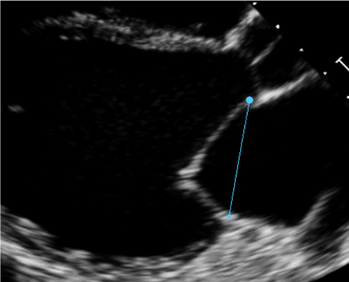
Mitral annulus: normal size at end-systole bi-commissural diameter (in TTE apical two chamber or TOE 50°) and antero-posterior (A-P) diameter (TTE parasternal long-axis view (Table 1, image 3) or TOE 135° (Fig. 5).
A-P diameter men <38 mm; women <36 mm; indexed <20.3 mm/m2
IC diameter men <46 mm; women <42 mm; indexed <24.4 mm/m2
Aorto-mitral angle: the angle between the AV and MV annular planes has been shown to correlate with the risk of systolic anterior leaflet motion (SAM) with LVOT obstruction post-MV repair. An angle <135° and typically below 120° has the potential risk of this complication. This is often exacerbated by a long posterior leaflet, which, if not addressed at the time of repair, can result in displacement of the coaptation line towards the LVOT and resultant SAM.
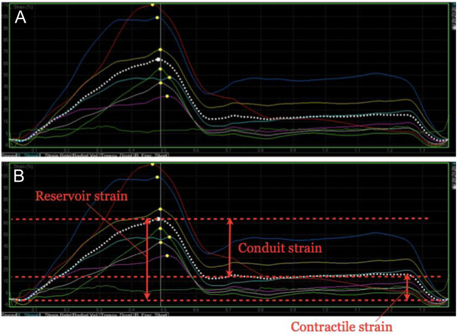
Figure 5.
LA strain imaging from the LA-focussed apical windows. The zero-reference point should be marked as mitral valve opening, which usually corresponds to the onset of the QRS on the ECG. A typical time–deformation curve is displayed in (A), with the coloured traces representing the six individual segments of the LA, and the dotted white trace the average value (or global strain). Reservoir, conduit and contractile strain are annotated in image (B). This process should be repeated from both the four- and two-chamber windows and the average values reported.
Mitral valve surgery (repair or replacement) has not been shown to confer survival benefits in secondary MR, although it may improve symptoms and quality of life (15). Surgery is therefore usually reserved for those who are undergoing concomitant revascularisation and have severe secondary MR or have symptomatic severe secondary MR, despite optimal medical therapy (± cardiac resynchronisation therapy if indicated) and who are considered low risk for surgery (15).
Anatomical characteristics identifying unfavorable outcome to surgical repair in secondary MR (Table 8) (22):
Table 8.
Characteristics that identify unfavourable outcome to MV repair surgery
| View | Measure or image | Explanatory note | Image |
|---|---|---|---|
| PLAX |
Image 1
Annular diameter |
Measure A-P annular diameter in systole |
|
| All views |
Image 2
Extent of calcification |
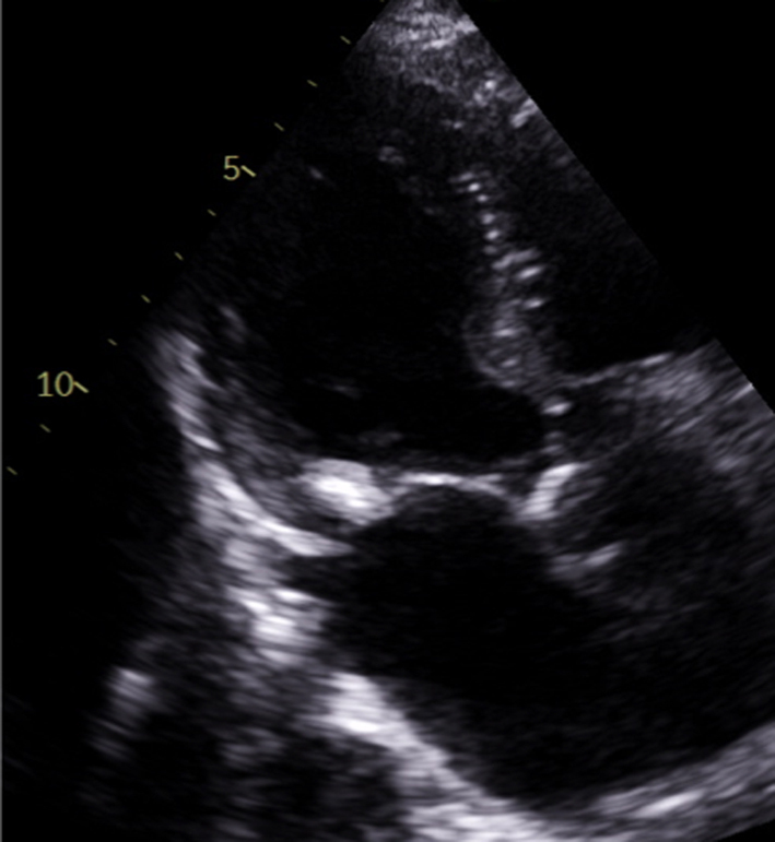
Describe the location and extent of calcification in the annulus, leaflets and subvalvar apparatus |
|
| PLAX |
Image 3
Coaptations height |
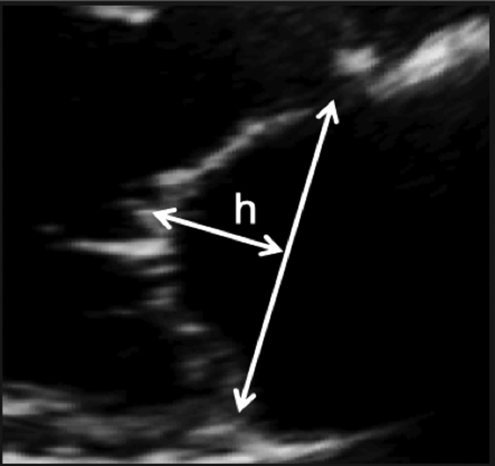
Zoom on the mitral valve in the parasternal long-axis view. Freeze the image and scroll through to mid-systole. Draw a line between the anterior and posterior annular points. Measure the coaptation height perpendicular to the plane of the annular line. |
|
| PLAX |
Image 4
Coaptation area |
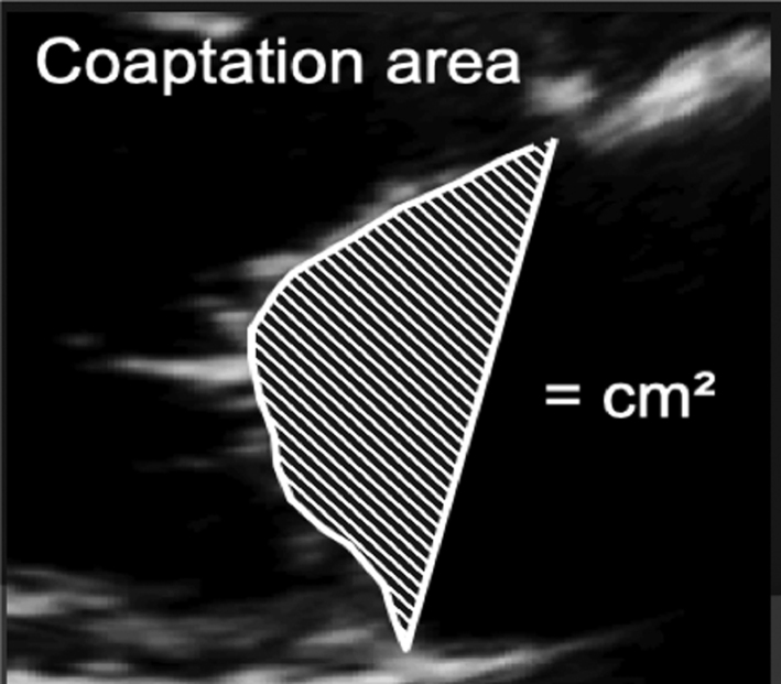
Once coaptation height has been measured, the area between the annular plane and the atrial surface of the leaflets can be measured. |
|
| PSAX – PM |
Image 5
Inter-papillary distance |
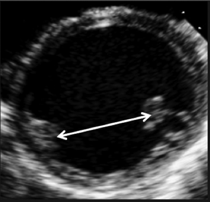
Freeze the image and scroll to end-systole. Measure the inter-papillary distance. |
|
| A4C |
Image 6
Systolic sphericity index |
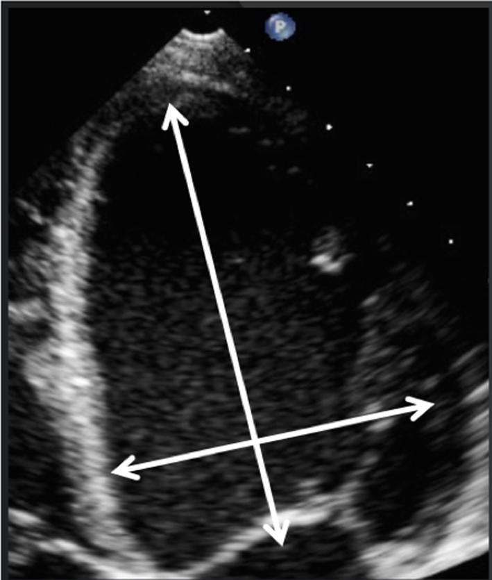
Adjust the depth of the image to focus on the LV. Freeze the image and scroll to peak systole. Measure the diameter and longitudinal dimension at the longest/widest. Divide the basal diameter by the longitudinal dimension, a value >0.7 Indicates adverse LV remodelling. |
|
leaflet coaptation height >10 mm;
leaflet coaptation area >2.5–3 cm2 ;
interpapillary muscle distance >20 mm;
global LV remodelling LVEDD 65 mm, LVESD 51 mm, ESV >140 mL;
systolic sphericity index >0.7.
Transcatheter intervention
For those where surgical intervention is contra-indicated or too high risk despite optimal medical therapy, transcatheter approaches such as MitraClip may improve symptoms (27). However, certain anatomical parameters may preclude MitraClip on the basis of poor outcome or the development of MS. In the case of primary MR, unfavourable parameters include a large flail gap, large flail width or small MV orifice < 4 cm2. In secondary MR, additional emphasis is given to the degree of LV dilatation and adverse remodelling along with adequate posterior leaflet length (Table 9).
Table 9.
Unfavourable parameters for percutaneous MV repair.
| Unfavourable parameters for MitraClip: primary MR | Unfavourable parameters for MitraClip: secondary MR |
| Large flail gap: separation of prolapsing segment from opposing leaflet >10 mm | LV end diastolic (18) (LVED) dimensions >70 mm |
| Flail width (size of prolapsing segment) >15 mm | LVED volume >200 mL |
| Small MV orifice <4 cm2 | LVED volume index >96 mL/m2 |
| Posterior leaflet length: Ideally >10 mm Can be considered >6 mm |
Haemodynamic consequences
Effect on left heart chambers
LA volume
The assessment of LA size is an important element in the investigation of mitral regurgitation (1, 15). LA dilatation secondary to volume overload is an expected finding in those with chronic severe MR. Normal LA volume, therefore, rules out chronic severe MR with near certainty (31). However, LA dilatation is a common finding in a number of other disease states and therefore cannot confirm severe MR. Estimation of LA volume by Simpson’s biplane method is recommended (Table 5, images 31, 32). Given the rapid onset, acute severe MR may be associated with little or no chamber dilation or adverse remodelling.
LV size and function
Severe chronic primary mitral regurgitation increases LV preload and will eventually lead to chamber dilation, eccentric hypertrophy and ultimately impaired function (2), all of which identify a suboptimal prognosis (17). Assessment of LV size and systolic function helps identify the optimum timing of intervention. Simpson’s biplane method provides an estimate of both diastolic volume (with indexing to BSA) and systolic contractile function (LVEF) and is crucial for the effective surveillance of patients with mitral regurgitation, these parameters should therefore be performed in all cases where image quality permits (7) (Table 5, images 28A,B). However, regional variations in chamber geometry and regional wall motion abnormalities limit the accuracy of this two-plane measure of a 3D structure. Given its improved accuracy, 3D estimates of chamber volume and function are recommended for the assessment and surveillance of chamber size, function and adverse remodelling (Table 5, image 29). In those with primary severe MR, an LVEF <60% is suggestive of impaired systolic function (17).
The assessment of diastolic function can be extremely challenging in patients with coexistent severe MR. It is likely that routine measures of diastolic function will suggest moderate or worse diastolic impairment due to increases in LA pressure secondary to severe MR. It is recommended that non-standard measures are performed when an assessment of diastolic function is necessary (32).
Effects on right heart chambers
Pulmonary artery pressure and right heart assessment
Increases in left atrial pressure secondary to severe mitral regurgitation translate to increased pulmonary artery capillary wedge pressure and, therefore, raised systolic pulmonary artery pressure (SPAP) (33). Estimating SPAP by echocardiography is important in patients with severe MR to ensure the appropriate timing of intervention. Secondary effects on right ventricular (RV) function and progressive secondary tricuspid regurgitation (TR) can also be seen. Concomitant primary tricuspid valve disease, while less common, may occur with degenerative or rheumatic valve lesions (34). Hence it is essential to note RV size, function, TR severity, mechanism and aetiology in addition to PAP estimation (1, 34).
Acute severe mitral regurgitation
Acute severe MR can result from either primary or secondary causes. Primary causes include leaflet perforation or destruction secondary to endocarditis, leaflet prolapse secondary to chordal rupture (because of either myxomatous valve degeneration or trauma) and papillary muscle rupture due to myocardial ischaemia (Table 2). Secondary acute MR is usually caused by ischaemia of the infero-lateral wall leading to regional wall motion abnormality with papillary muscle dysfunction and restricted MV closure (tethering) of the posterior leaflet. Since the onset of MR is acute, the sudden increase in volume results in a rapid and significant increase in LAP with no immediate change in the chamber size (non-compliant). Hence acute severe MR may be associated with a normal size LA. The significant increase in LAP will result in a rapid rise in pulmonary venous pressure, may result in acute pulmonary oedema and may progress to cardiogenic shock.
Special patient group
Barlow’s MV disease is characterised by excessive myxomatous leaflet tissue, along with annular dilation, leaflet thickening, bileaflet prolapse and chordal lengthening (35). Due to the dynamic process of prolapse through systole, the MV remains competent until the point at which prolapse causes loss of apposition, typically in mid- to late-systole. Therefore, when non-holosystolic MR is present, the regurgitant volume is lower than the single-frame CF Doppler appearance or EROA suggest (1). Furthermore, significant prolapse of the MV leaflets results in traction via the chordae of the papillary muscle. Papillary muscle wall stress is increased as a consequence of systolic traction and has been proposed as the cause of papillary muscle fibrosis (and additionally basal infero-lateral wall) in such patients (35).
Mitral annular disjunction (MAD) has been proposed as a potential risk factor for sudden cardiac death (SCD) in patients with mitral valve prolapse. It is identified as a separation between the posterior mitral valve leaflet hinge-point and the ventricular myocardium, ensuring that the distance of the ‘muralised’ posterior leaflet base at end-systole is not interpreted as the distance of MAD (Table 5, image 4). This is often accompanied by late systolic peaking of the lateral wall S’ signal with systolic curling motion of the basal myocardium. However, recently published data suggests that this observed phenomenon is not unique to MVP; indeed it has been described in patients with ventricular arrhythmias but without MV disease (36). Furthermore, a very recent publication has described MAD in a series of normal hearts using computerised tomography (37). At the current time, it appears MAD is likely to be a normal finding, where it is the extent of disjunction rather than its presence which may be important (38). Further studies are needed.
Due to the association with ventricular arrhythmias and SCD, the presence of Barlow’s MV should be described in the report conclusion.
Novel imaging techniques in the assessment and surveillance of MR
While not advocated for routine clinical practice or recommended within international guidance for the timing of mitral valve intervention, the emerging and novel parameters described below are of growing interest in the assessment of mitral valve disease and may, when considered in the clinical context, prompt more careful consideration of surveillance frequency.
Global longitudinal LV strain
The application of strain imaging is becoming more widespread and has increasing clinical utility in echocardiographic practice, speckle-tracking derived strain being the most commonly utilised method (7) (Table 5, image 30). Unfortunately, there remains significant inter-vendor variability, such that a single reference interval would not suffice for all practitioners. Additionally, it is not clear whether different versions of strain software provide comparable results. Individual vendors currently provide reference intervals for specific platforms and software versions. However, strain tools are of value when used sequentially on a single individual in order to help identify subclinical interval changes in LV performance (7). Therefore, GLS may be helpful in identifying subclinical LV dysfunction in the setting of serial echocardiograms and may help determine appropriate follow-up intervals or timing for intervention (39).
LA function analysis
Normal left atrial function is a key contributor towards normal cardiac output. LA function is divided into three phases, each of which is characterised by specific functional capabilities. The reservoir phase reflects LA expansion during ventricular systole, and describes the ability of the atrium to ‘absorb’ pulmonary venous return. The conduit phase occurs immediately after mitral valve opening, and describes early diastolic atrial emptying (corresponding with the E wave on the mitral Doppler waveform), combined with diastolic pulmonary venous return. Although frequently considered a passive phenomenon, early diastolic emptying of the LA is contributed to by elastic recoil of the normal LA. Finally, the contractile phase represents active atrial emptying or contraction and corresponds with the MV Doppler A wave and the p-wave on the ECG. When sinus rhythm is lost, there is no contractile phase, and reservoir and conduit phases are of equal magnitude.
There are two main methodologies by which atrial function can be assessed. The volumetric method involves the measurement of LA volume at different time points of the cardiac cycle, from which the three phases of atrial function can be derived. This approach is somewhat time-consuming and is not practical for busy echo departments, although the assessment of the ‘total left atrial emptying fraction’ (TLAEF), which is synonymous with the reservoir phase, can be obtained relatively easily from the maximal and minimal LA volume using the following formula (40):
 |
The second method utilises speckle strain imaging. All three phases of LA function can be obtained from focussed 2D images of the LA. The BSE recommended technique for obtaining LA strain indices is demonstrated in Fig. 5, and has a large published evidence-base (40, 41, 42). It is important to appreciate that although a negative strain value is conventionally assigned to phases in which myocardial fibres reduce in length (i.e. during contraction), the overwhelming majority of studies of atrial strain, including recently published normative reference intervals from the NORRE dataset, describe all three phases of LA function as a positive value (41, 42, 43).
LA function indices are particularly useful when assessing patients with chronic MR secondary to primary mitral valve disease. LA strain reflects the severity of mitral regurgitation, alterations in LV systolic and diastolic function, increases in PA pressure and the presence of cardiovascular symptoms (44, 45). As such, in moderate and severe MR there are only minor reductions in reservoir and contractile strain, but in patients with a guideline indication for MV surgery, LA function is markedly reduced, almost certainly as a consequence of interstitial fibrosis developing within the LA myocardium (44, 46, 47). In prospective studies, reductions in reservoir strain are associated with poor cardiovascular survival, increased likelihood of AF during follow-up, or the development of a guideline indication for cardiac surgery (46, 48, 49, 50).
In asymptomatic patients with moderate to severe MR and no guideline indication for mitral valve surgery, a TLAEF < 51%, or reservoir strain < 29% may be useful in identifying those patients in whom early surgical intervention may be indicated, or at least identifying those patients who may benefit from increased frequency of follow-up (49).
Proportionality of MR
Unlike chronic severe primary MR where adverse LV remodelling may be caused by the MR, secondary MR typically develops as a consequence of LV disease and dysfunction (27). Therefore, treatment strategies are directed towards the underlying LV disease process (15). However, difficulties have arisen when attempting to decipher which group of patients may or may not benefit from mitral valve intervention (18). The degree of MR (EROA) in the context of the degree of adverse LV remodelling may therefore provide useful insight into the haemodynamic significance of MR and its contribution to LV dilatation (50). When the LV is severely dilated, and with severely impaired systolic function, a large EROA and RF reflect a degree of secondary MR that is proportionate to the degree of LV dilation. However, less severe LV dilatation with a similarly large EROA and RF may indicate a degree of MR that is disproportionate to the degree of LV dilatation alone (18). This latter group have been shown to benefit from MR reduction via transcatheter intervention (Fig. 6) (51). Therefore, parameters quantifying LV size to the proportion of MR may identify those who will benefit most from such therapies. Although not yet established in routine clinical practice, an EROA:LVEDV ratio of 0.14 (mm2/mL) may differentiate between those in whom medical therapy should be optimised and those who may be considered for transcatheter therapy.
Figure 6.
Proportionate vs disproportionate MR.
Key points for the assessment of MR
Consider the anatomical findings that are consistent with severe MR.
PISA estimates of MR parameters assume perfect hemispherical PISA geometry. As this is rarely the case, especially in the setting of secondary MR, PISA estimations should always be considered alongside other indicators of MR severity.
The assessment of MR volume and MVA by the continuity method is limited through: multiple measures required to perform calculations of valve area and regurgitant volume, the assumptions of anatomical geometry necessary when making calculations and the presence of other valvular or congenital pathology that alter LV and/or MV SV.
VC measured by CFD is an effective measure of regurgitant orifice area and therefore MR severity, with particular strength in eccentric jets.
Consider the haemodynamic indicators that suggest MR is severe or non-severe.
Novel indicators of MR severity may provide useful insight in the surveillance of patients with MR.
Mitral stenosis
Despite the declining incidence of rheumatic fever in industrialised countries over the past 40 years, the most common cause of mitral stenosis (MS) remains rheumatic disease (15). Although other aetiologies of MS exist, including post-inflammatory processes such as systemic lupus erythematosus (SLE) or rheumatoid arthritis; radiation-induced valve disease; significant annular calcification; congenital abnormalities and mechanical obstruction by tumour or thrombus, these aetiologies and mechanisms are rare and constitute a very small percentage of those presenting with clinically significant mitral stenosis. Commissural fusion (with thickened rolled free edges) is the hallmark of rheumatic valve disease. With the ageing population, the incidence of calcific (degenerative) MS is increasing and poses challenges to assessment; the stenotic orifice is more planar (rather than funnel-shaped, as in rheumatic MS), and complicates the assessment by planimetry. Additionally, the haemodynamic assessment and symptoms may be discrepant with Doppler measures (1).
When MS is suspected, transthoracic echocardiography remains the primary imaging modality for the evaluation of probable aetiology, lesion severity and to help determine the appropriate interventional plan. Consequently, a complete assessment of the stenotic MV does not focus solely on mitral valve area and transvalvular gradients but also considers sequelae, including MR, valve anatomy and chordal involvement, concomitant aortic valve disease, LA size and pressure, pulmonary pressures and right heart size and function (15).
Aetiology and mechanism
The initial assessment of the valve is a visual examination of the degree and distribution of thickening, fibrosis and/or calcification, along with the extent and appearance of leaflet excursion. Although the valve should be assessed in both the parasternal and apical windows, valve anatomy and degree of leaflet restriction are best appreciated in the long- and short-axis parasternal windows.
Characteristic 2D features in those with rheumatic mitral stenosis include:
Leaflet fibrosis and thickening that is predominantly confined to the tips and commissures (mitral valve calcification tends to spare the leaflet tips). Thickening comes first with calcification later (Table 10, images 1 and 6).
Chordal thickening, fusion and shortening.
Relative mobility of the leaflet base in comparison to leaflet tips. In rheumatic disease, the tips and commissures tend to be fused and restricted so that the valve appears to ‘dome’, this is also referred to as a ‘hockey stick’ or ‘elbowing’ appearance.
Evidence of commissural fusion demonstrated in the PSAX or 3D views (Table 10, image 6).
Table 10.
Guide to image acquisition in mitral stenosis
| View | Measure or image | Explanatory note | Image |
|---|---|---|---|
| PLAX |
Image 1
Visual assessment of annular calcification, leaflet thickness and excursion |
Measure leaflet tip thickness in mid-diastole and describe the degree of leaflet restriction Describe the extent of annular calcification and how far this extends into the posterior leaflet Report features suggestive of aetiology |
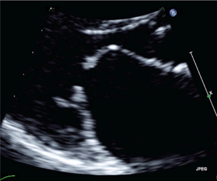
|
| A4C |
Image 2
Mean pressure gradient |
Zoom on the MV in the A4C view. Apply CFD to identify the centre of the MV orifice and direction of flow. |
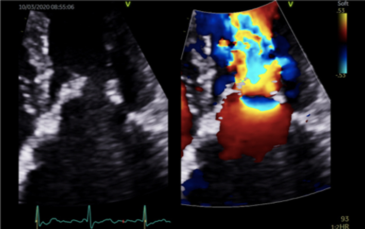
|
| Image 3 | Place the cursor through the centre of the orifice and aligned with the flow (tip: place the cursor through the highest PISA seen within the LA |
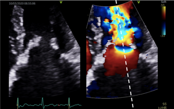
|
|
| Image 4 | Enter CW Doppler mode, optimise and record several beats. Trace the MV signal. |
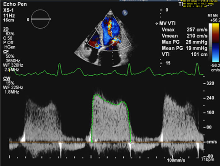
|
|
| Image 5 | Poorly optimised images can lead to overestimation of the Doppler signal and, therefore, overestimation of the mean pressure gradient |
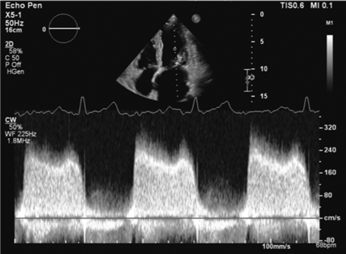
|
|
|
Image 6
2D Planimetry |
In the PSAX view at the level of the MV, find the plane of the leaflet tips by scanning back and forth through the valve. Once in the correct plane, zoom on the valve and freeze. Scroll through the loop to find the point in diastole when the leaflet excursion is at its greatest. Trace along the blood-tissue interface of the leaflet tips (tip: although it is not recommended to trace around CFD overlaid onto the MV orifice, applying CFD can help identify orifice geometry and therefore guide more accurate measurement). |
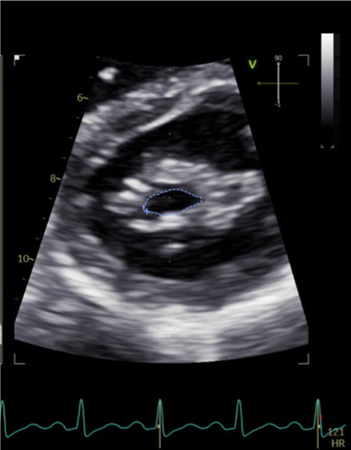
|
|
| Parasternal window |
Image 7
3D – orthogonal plane imaging |
Orthogonal plane imaging can help ensure that orifice planimetry is performed at the leaflet tips. Place the cursor at the level of the MV tips and enter orthogonal plane imaging to demonstrate the MV orifice; the MVA can then be traced. Limitation: Off axis imaging in the PLAX plane will lead to an oblique image of the MV and overestimation of the MVA in the orthogonal view. |
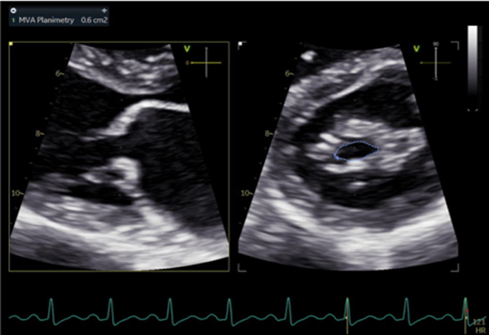
|
| PLAX |
Image 8/9
3D volume imaging |
In the PSAX view at the level of the MV, acquire a 3D zoom dataset; this should be optimised to include the entire mitral annulus but no more than a few millimetres above leaflet height. Acquire the 3D volume dataset. Using multi-plane reconstruction, crop the dataset to identify three planes of the valve. Scroll through the loop to find the point in diastole when the leaflet excursion is at its greatest. Adjust the plane of view that is en-face with the valve to achieve parallel alignment with the orifice. Trace along the blood-tissue interface of the leaflet tips to measure MVA. |
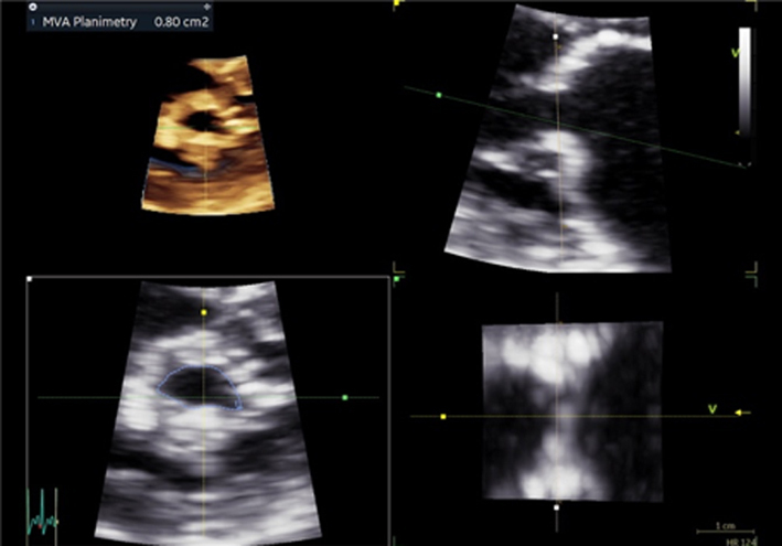
|
| A4C |
Image 10
P½t |
Apply CFD to the A4C to identify the MV orifice. Place the cursor through the centre of the orifice (tip: when a PISA is seen within the LA, ensure the cursor is positioned through its highest point). Enter CW mode, the signal can be optimised by: ensuring parallel alignment with the trans-mitral flow, adjusting the velocity scale to maximise the Doppler signal size. Optimising signal gain and reject to reduce transit-time artefact. Measure the deceleration slope from the peak of the signal to the baseline of 0 cm/s. If the E signal is bi-modal, ignore the initial descent and measure the slope from mid-diastole onwards When the patient is in AF, measure according to the described guidance. |
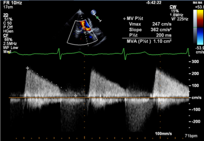
|
| PLAX and apical views |
Image 11 Continuity estimates |
LV SV is calculated at the level of the LVOT by multiplying the CSA by LVOT PW VTI (tip: assuming circular geometry of the LVOT often leads to underestimation of SV and consequently MVA. SV can also be estimated by 2D biplane and 3D estimates of LV EDV and ESV, similar limitations of AR and MR apply however) Apply CFD to the A4C to identify the MV orifice. |
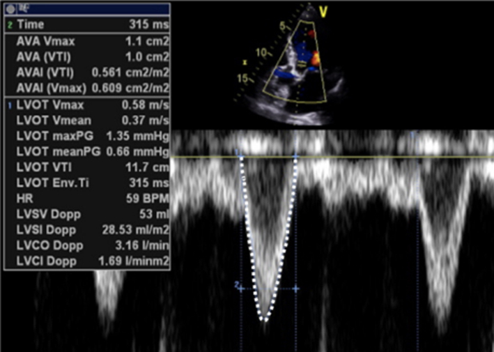
|
|
Image 12 Continuity estimates |
Place the cursor through the centre of the orifice and align with flow (tip: when a PISA is seen within the LA, ensure the cursor is positioned through its highest point). Enter CW Doppler mode and optimise the signal. Trace the MV signal. |
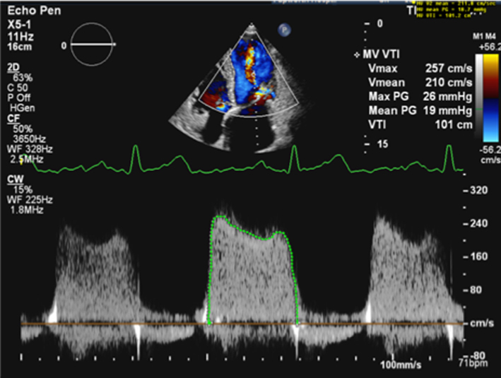
|
|
| A4C |
Image 13
PISA estimates of MVA |
Zoom on the MV in the A4C view. Apply CFD and adjust the baseline in the direction of flow (tip: a lower Nyquist limit is more obvious when returning to normal CFD assessment and avoids acquiring the remainder of the study at a lower alias velocity). Freeze the image and scroll through to mid-diastole. Measure the PISAr from the point of the leaflet tips to the greatest radius. |
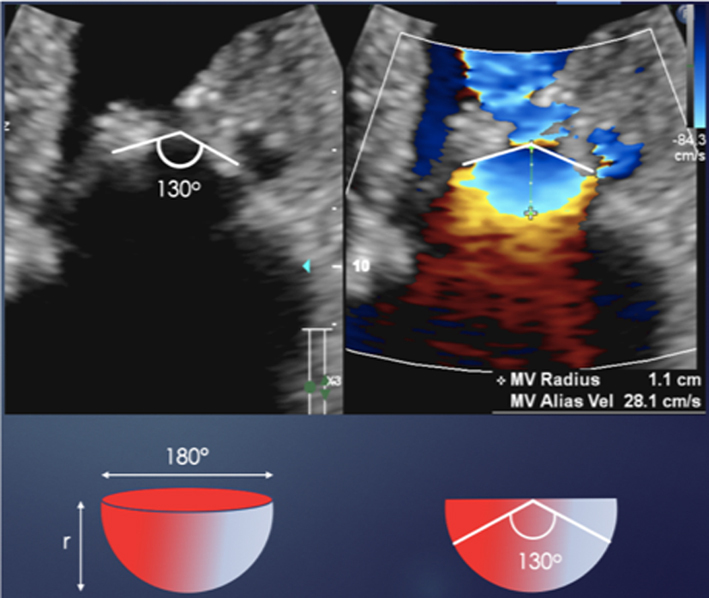
|
| Image 14 | Supress CFD and measure the angle of the atrial surface of the MV. This measure requires appropriate software. Unfreeze the image and place the cursor through the centre of the orifice (tip: place the cursor through the highest PISA radius) Enter CW mode and optimise the signal according to the guidance above. Trace the MV signal. |
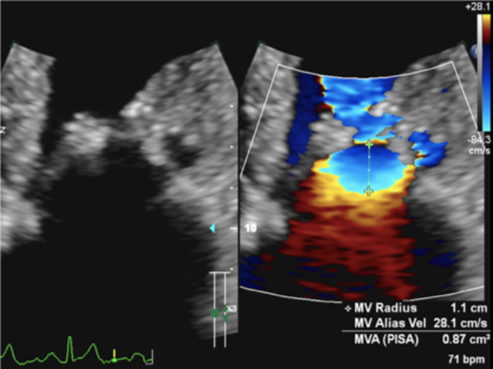
|
Grading mitral stenosis severity
MS severity is described by the mitral valve area (MVA) and the mean MV gradient (MG). Indirect estimates of MVA are based on measures of transvalvular Doppler profiles and are therefore influenced by both loading conditions and coexistent valvular disease (Table 11) (1).
Table 11.
Grading MS severity.
| Mild | Moderate | Severe | |
| Specific finding | |||
| Mitral valve area | >1.5 cm2 | 1.0–1.5 cm2 | <1 cm2 |
| Supportive finding | |||
| Mean gradient (mmHg) | < 5 | 5–10 | >10 |
| SPAP (mmHg) | <30 | 30–50 | >50 |
Data from the EAE/ASE table for grading the severity of MS by echocardiography (53).
Heart rate (HR) and rhythm
Since all Doppler-based estimates of MVA and MG are influenced by HR and rhythm, these should be routinely reported. For the surveillance of MVA and MG, variations in HR and rhythm should be excluded as the cause of any interval changes in these parameters. When the patient is in AF, estimation of MVA and MG should be avoided during extremes of HR and R-R interval. It is recommended that parameters are calculated on the basis of averaged measures from five beats or from measures made on R-R interval matched beats (see BSE Minimum Dataset (7)).
Trans-mitral pressure gradient
Reduced MV opening secondary to intrinsic leaflet restriction prevents complete LA diastolic emptying and eventually leads to increased LA volume and consequently pressure overload (1). The relationship between LA pressure and MVA is therefore inverse, where a decrease in MVA increases LAP. Thus, when cardiac loading conditions and both LA and LV compliance are normal, the LA-LV pressure difference is proportional to the degree of valvular stenosis and can be considered a good indicator of MS severity (1). In this setting, MS is considered mild when the mean transvalvular gradient is less than 5 mmHg and severe when exceeding 10 mmHg (15). However, the mean transvalvular pressure gradient is significantly influenced by alterations in loading conditions, including changes in LA and LV diastolic pressures. Due to load and flow dependency, mean transvalvular pressure gradient is not a good indicator of MS severity where cardiac disease coexists, particularly in the presence of AF. Increases in LV diastolic pressure in the presence of aortic regurgitation (typically moderate or more) and/or LV diastolic dysfunction reduces the LA-LV pressure difference. This results in a reduction in the mean pressure difference and therefore measured gradient (1). Conversely, moderate or more MR will increase LA pressure and further increase the LA-LV pressure difference, thereby increasing the mean pressure gradient (1).
Mitral valve area methods and limitations
The essential measurement for the diagnosis of MS severity is the estimation of MVA. It can be measured directly by tracing the anatomical orifice area using 2D or 3D imaging (direct planimetry) or indirectly through measures of transvalvular Doppler profiles (P½t, continuity and PISA) (1, 15). Since planimetry is a direct measurement of the stenotic orifice, it is less influenced by loading conditions compared to other estimates of MVA. Hence it is considered the reference standard for area measurement and grading of MS severity (12).
Planimetry
2D planimetry
2D planimetry of the MV orifice is performed in the PSAX view of the MV with careful angulation and tilting of the beam to ensure imaging of the leaflet tips (Table 10, image 6). The image is frozen and scrolled through until the point of maximal valve opening. Image optimisation is achieved by reducing sector width and scan depth to increase temporal resolution, or applying 2D zoom to increase both temporal resolution and image size (1, 15). Image gain and compression are optimised to avoid ‘flaring’ of the leaflet tips and ensure a distinct definition of the blood-tissue interface. If not optimised and the image over-gained, there is a risk of underestimating MVA and therefore overestimating the degree of MS severity. Conversely, the MVA may be overestimated if the scanning plane is not aligned en-face with the orifice and bisects through the body of the leaflets. For this reason, 2D planimetry tends to overestimate MVA. Although tracing the CFD contour overlaid onto MV orifice is not recommended to estimate MVA, CFD is extremely helpful in identifying the position and geometry of the orifice and assist with MVA measurement on the 2D image.
3D planimetry
Imaging of the MV can be performed using two modes of 3D imaging formats – biplane imaging and 3D volume imaging.
Biplane imaging provides simultaneous images from a second scanning plane. Although the second imaging plane is usually orthogonal to the primary image, any degree of rotation can be applied. When scanning in the long-axis view of the MV, orthogonal imaging in a plane at the level of the MV tips can provide an on-axis view of the MV orifice (Table 10, image 7). However, for accurate planimetry of the valve area, biplane imaging relies on the MV orifice lying parallel to the orthogonal imaging plane.
The advantage of 3D volume imaging is the ability to view anatomy from any perspective within the dataset. Cropping the dataset using multi-plane reconstruction software allows accurate alignment of the imaging plane at the level of the leaflet tips (narrowest point of the orifice), providing a truly en-face view of the orifice (15) (Table 10, image 8). This method avoids the risk of overestimating MVA and, therefore, underestimating MS severity that is associated with 2D planimetry.
Pressure half-time
As previously described, when left atrial pressure (LAP) is raised secondary to mitral stenosis, the time taken for early trans-mitral velocity to fall by half its starting value can provide an estimate of MVA (1). The high-pressure difference between the LV and LA caused by MS results in maintained trans-mitral velocities throughout diastole and is reflected by an extended time for pressure to fall by half and consequently shallower deceleration of the MV E wave (Table 10, image 10). MVA is then calculated by dividing an LV relaxation constant value of 220 by the P½t (equation 5).
However, the rate of pressure decay and the time taken for pressure to fall by half is not solely determined by the mitral orifice size and is also influenced by a number of physiological and patho-physiological loading conditions that affect intra-cardiac flow and pressure (15). As these naturally affect the rate of pressure fall, they also alter the P½t and, therefore, the estimate of MVA. For instance, for a given MV stroke volume and MVA, both severe aortic regurgitation and reduced LV compliance will increase LV pressure throughout diastole, resulting in more rapid equalisation of LV-LA pressure difference and a shorter time for pressure to fall by half; the outcome is an overestimated MVA (1). Conversely, when LAP is raised further by moderate or severe mitral regurgitation, the half-time for pressure equalisation is extended and the MVA underestimated. The P½t is additionally influenced by LA compliance (LAC), where the rate of pressure decay decreases as LAC decreases. P½t estimate of valve area is therefore considered the least accurate of the indirect Doppler estimates available during TTE.
The rate of E wave deceleration is often more rapid in the early descent than it is in later diastole. This results in a bi-modal E waveform where the initial E deceleration slope is steep before becoming shallower for the remainder of diastole. In this scenario, the P½t estimate of MVA should be measured on the shallower second phase of the deceleration slope. In the rare scenario of the deceleration slope being curvilinear, measurement may not be possible.
When the patient is in AF, adequate rate control permits uninterrupted measurement of the E deceleration and estimation of MVA by P½t. However, when the patient is in SR, elevated HR (>100 bpm) or first-degree AV block results in E/A fusion and truncation of the E deceleration slope, therefore preventing accurate measurement of the P½t. In these scenarios, estimation of MVA by other methods is recommended.
Continuity equation
Although a recognised method of assessing valve area, continuity estimates of MVA are limited by the assumption that SV is equal at both the LVOT and mitral valve sites. Given that MVA is calculated as LVOT SV divided by MV VTI, the presence of aortic regurgitation increases LVOT SV and therefore results in an overestimated (15) MVA. Conversely, when mitral regurgitation is present, the SV at the MV level is greater and the MVA consequently underestimated and MS severity overestimated. In patients with AF, SV varies significantly from beat-to-beat. If a continuity estimate is going to be made in the setting of AF, measures should be made during similar R–R intervals. Additionally, because of the number of measurements required to estimate MVA by continuity equation, measurement error and suboptimal Doppler alignment can lead to inaccurate estimates of MVA (1).
PISA
Although more commonly used to calculate regurgitant orifice area and volume for mitral regurgitation, the PISA method can also be utilised to calculate MVA in those with MS (Table 10, image 13). However, the geometry of the MR PISA is different to that of the stenotic MV PISA. Because the atrial surface of the MV is not planar in those with rheumatic valve disease, typically being funnel shaped, the PISA geometry is more conical than hemispherical (Table 10, image 13) and a correction factor must be applied to account for the overestimation (Table 12, image 13) (1). This correction factor is determined by measuring the angle of the atrial surface of the leaflets in diastole. Given that the PISA equation assumes a flow rate and MVA based on a planar orifice with a hemispherical shell of 180°, multiplying the flow rate by the angle of the atrial surface of the leaflets divided by 180 corrects for the non-planar geometry and provides a more accurate estimate of MVA (52) (equation 9).
Table 12.
Wilkins score.
| Score | Leaflet mobility | Valve thickness | Subvalvular thickening | Valvular calcification |
| 1 | Highly mobile with little restriction | Normal thickness (4–5 mm) | Minimal chordal thickening | A single area of calcification |
| 2 | Decreased mobility in mid-portion and base of leaflets | Mid-leaflet/marginal thickening | Chordal thickening 1/3 of chordal length | Confined to the leaflet margins |
| 3 | Forward movement of the valve leaflets in diastole | Total leaflet thickening (5–8 mm) | Chordal thickening 2/3 of chordal length | Extending to mid-leaflet |
| 4 | No or minimal forward movement of leaflets in diastole | Severe thickening (>8 mm) | Complete chordal thickening to papillary muscle | Throughout most of the valve leaflets |
 |
This method is of particular value when other Doppler-based methods of estimating MVA are rendered inaccurate by variable SV (AR, MR and AF) or when LA or LV pressures are increased for reasons other than MS (MR and LV diastolic dysfunction). However, the wider application of this method is limited by the inability to measure the angle of the MV leaflets on many echo machines (52).
LA volume
As already discussed, chronic pressure loading of the LA results in adverse remodelling to increased LA chamber size. However, increased LA volume may be seen in a number of disease processes and does not confirm severe MS in isolation, although normal LA volume almost certainly excludes severe MS (Table 5, images 31, 32).
Pulmonary artery pressure
Similar to the haemodynamics seen in MR, increased LA pressure secondary to severe MS translates to increased pulmonary artery capillary wedge pressure and therefore systolic pulmonary artery pressure (Table 5, image 33). Estimating systolic PAP by echocardiography is important in patients with severe MS to ensure the appropriate timing of intervention (12).
Considerations for intervention and the role of echocardiography
When clinically significant MS is present, appropriate patient selection for intervention is determined by the aetiology of mitral stenosis and the associated valve anatomy (1, 17). When the underlying cause is post-rheumatic valve disease, percutaneous balloon mitral valvuloplasty (PBMV) can be considered. The procedure aims to split the fused commissures, thereby increasing valve opening. However, when the aetiology is post-radiation/non-rheumatic post-inflammatory fibrosis or there is diffuse leaflet calcification present, the outcome to PBMV may be unfavourable and surgery is preferred. To aid risk stratification, a number of scoring systems exist. The most commonly applied is the Wilkins score, which assesses MV anatomy in terms of leaflet mobility, thickness, calcification and sub-valve characteristics (Table 12). The minimum score is 4, and the maximum 16 (1). A score < 8 suggests anatomy that is favourable for PBMV with good long-term outcomes and prolonged freedom from reoperation (15–20 years) and restenosis rates.
Contraindications to percutaneous mitral commissurotomy:
MVA >1.5 cm2
LA thrombus
more than mild MR
severe bi-commissural calcification
absence of commissural fusion
severe concomitant aortic valve disease, or severe combined tricuspid stenosis and regurgitation requiring surgery.
Key points
2D planimetry overestimates the MVA when the imaging plane is not parallel with the plane of the orifice.
3D imaging overcomes the limitations of non-parallel 2D imaging and allows the operator to view and planimeter the MV orifice at the leaflet tips.
Continuity estimates of the MVA are limited by the multiple measures required for the calculation and by coexistent valvular and congenital pathologies that result in a SV mismatch between the LVOT and MV.
Estimates of MVA by P½t are heavily affected by variations in LA and LV compliance, MR (with worsening accuracy as MR severity increases) and increases in LV diastolic pressure secondary to either LV diastolic dysfunction or AR.
Mean trans-mitral pressure gradient is increased or decreased by other pathologies that increase or decrease the LA-LV pressure difference (MR, AR and diastolic dysfunction).
Advanced echocardiographic assessment
Stress echocardiography
The clinical indications for stress echo in patients with mitral valve disease can be divided into two categories: severe valve disease without symptoms and non-severe disease with symptoms (53). In both scenarios, the aims of the test are to determine whether the patient is symptomatic or if valve disease is truly severe and therefore requires intervention.
Exercise can be performed by either upright-treadmill or semi-supine bike. When stress is performed by treadmill, images are acquired at baseline and immediately post-stress (within 90 s of exercise cessation) in the left lateral decubitus position (1, 53). When performed by semi-supine bike, images are acquired at baseline, low workload and peak stress (53). The protocol chosen should reflect the patient’s physical capability and should allow them to achieve their maximum exercise capacity. For those who are physically able and are not significantly limited by symptoms, the Bruce protocol can be undertaken on the treadmill or the WHO protocol (2 min increments of 25 or 50W increments) on the semi-supine bike. However, for those who are significantly limited by symptoms or who have limited physical capability, a modified-Bruce or Naughton protocol may enable greater exercise on the treadmill, or a protocol of 10W increments at 2 min on the bike.
Although the primary investigation is to clarify the severity of MR or MS, coexistent heart disease that may contribute to or account for symptoms should also be excluded. Assessment of coronary artery disease and regional wall motion abnormalities should be performed at peak stress while an assessment of diastolic function and filling pressures should be made at lower HR in those with no more than moderate MR or MS at rest (1).
Primary mitral regurgitation
When primary MR is at least moderate and the patient is symptomatic, stress echo can help identify the following haemodynamic and functional responses to exercise that are known to be associated with poor long-term outcomes:
increase in MR severity by >1 grade
dynamic PH (> 60 mmHg)
limited LV contractile reserve (LVEF augmentation < 5% or GLS < 2%)
limited RV contractile reserve (TAPSE < 18 mm) (53).
When resting MR is not severe, the stress echo image acquisition sequence should include and be in the order of:
CFD for post-processing of PISA and VC
MR CW for PISA quantification
TR velocity to assess SPAP
Standard LV views to assess for regional/global impairment (51).
Assessment of TR velocity should also be made early during exercise since early increases in SPAP are indicators of more significant disease (53).
Secondary mitral regurgitation
When MR is secondary, stress echo is indicated to compare exertional symptoms with baseline parameters and dynamic changes with exercise. Current guidelines recommend that stress echo for the assessment of secondary MR is indicated in the following scenarios (53):
When resting LV systolic function and the degree of MR are disproportionate to the degree of symptoms.
Following recurrent and unexplained episodes of pulmonary oedema.
To assess moderate MR prior to already planned coronary artery bypass grafting to identify those who would benefit from dual CABG and MV surgery.
Persistent PH following MV repair surgery.
The following findings are associated with a worse prognosis:
increase in severity as identified by increase in EROA by > 13 mm2, and
dynamic PH (> 60 mmHg).
Mitral stenosis
Stress echo is useful for assessing the haemodynamic significance of mitral stenosis and is recommended in both severe asymptomatic and non-severe symptomatic settings. Although exercise echo is primarily for the assessment of symptom development, the echo measures acquired during exercise stress echo are:
-
CW MV for mean pressure gradient
MVG > 15 mmHg with exercise
-
CW TR for estimate of SPAP
SPAP > 60 mmHg.
When the MVA is < 1.5 cm2 but > 1 cm2, stress echo is indicated for the planning of pregnancy or major non-cardiac surgery irrespective of suitability of PBMV.
Severe asymptomatic MS
When the MVA is < 1 cm2 but the patient remains asymptomatic, exercise stress echo is recommended to assess for the development of symptoms. When MVA is < 1.5 cm2 and BMV is feasible, exercise stress echo is recommended to unmask exertional symptoms or assess for indicators of haemodynamically significant MS.
Symptomatic non-severe MS
The primary indication for exercise stress echocardiography in those with symptoms and non-severe MS is the assessment of exertional symptoms in the context of the simultaneous haemodynamic findings. MS is severe when the markers above are satisfied. A significant SPAP raise during exercise is typically seen early and is associated with the development of exertional symptoms. Therefore, this parameter should be carefully assessed in the early stages of exercise (53).
Transoesophageal echocardiography (TOE)
TTE is the first line in the assessment of MV disease. Where echo windows are limited, or further clarification in aetiology, mechanism and reparability of the valve lesion is needed, TOE offers high-resolution imaging (since the probe lies closer to the MV, without interference from lung or chest wall). TOE allows comprehensive assessment of the valve anatomy and both regurgitant jet and stenotic orifice characteristics (9). When interventions such as MV repair or percutaneous mitral commissurotomy are contemplated, TOE provides essential morphological data to guide patient selection. It is essential to be aware of the potential haemodynamic changes in the fluid depleted and sedated patient, and the consequences on mitral valve assessment. This is particularly relevant in MR where its severity can be underestimated. Blood pressure and heart rate are therefore essential considerations when investigating MR, and should always be recorded and their effect considered.
TOE protocol
A systematic approach is encouraged. The key imaging planes include oesophageal views at 0°, 50°, 90° and 135° and trans-gastric views at 0° and 90°. However, careful observation throughout the changing probe angles ensures all pathology is correctly identified. Probe angles given are guidance only and the anatomical structures are the focus when optimising each view. Landmarks are essential in identifying structures (aortic valve adjacent to anterior leaflet, left atrial appendage identifies lateral portion of valve P1/A1/ALC, inter-atrial septum (IAS) identifies medial portion of MV, typically P3/A3) (9). Each view is performed with and without colour Doppler, simultaneous 2D only and 2D with CF Doppler imaging is recommended to gain a full appreciation of anatomy and flow. Additionally, and where appropriate, PWD and CWD (TTE section for further details) can provide further information. 3D echo imaging provides additional functional anatomy. 3D colour helps to locate the regurgitant jet and describe the precise location and extent of underlying lesion(s).
Views and corresponding anatomy (Fig. 7):
0°: five chamber mid-oesophageal (ME) view: may require slight flexion of the probe to open the LVOT, the LV is foreshortened in this view. This view is an oblique plane across the MV; segments viewed A2 and P2-1.
0°: four chamber ME view: the probe is retroflexed to visualise the true LV apex, the LVOT is closed off and the image is centred on the MV. This is an oblique plane through the MV; segments viewed are typically A2-1 and P1. A sweep of the MV segments can be performed by advancing the probe slightly to view A2-P2 and further still A3-P3 (high/mid/low oesophageal views). However, note the views are oblique planes through the valve and not perpendicular to the coaptation line. These views give a useful overview of lesions and their location. Further confirmation is then required through rotation of the plane angles as described below.
50°: ME commissural view. This is a plane through the entire coaptation line with P3, A2, P1 segments usually in view. The LAA is usually partially in view and adjacent to P1. Rotation of the probe right/left will identify the extremes of the valve, the commissures (towards LAA-ALC is seen).
90°: ME view usually allows an image plane through P3 and all three segments of the anterior leaflet, A3-2-1. The LAA locates the lateral aspect of the valve (A1).
135°: ME long-axis view is optimised to open the LVOT and transect the AV/aorta. The central portion of the MV is seen A2 (nearest AV) and P2.
0°: Trans-gastric (TG) view. By advancing into the stomach, the probe is flexed (may also require slight rotation of the probe itself), and the LV in short axis is viewed. The MV is brought into view by further flexion of the probe. All six segments and commissures can be viewed with this en-face view of the valve seen from the LV surface. The probe can be gradually retroflexed, sweeping through the LV in short axis from base (MV level) through to PMs and apex. The subvalvular apparatus can be studied.
90°: TG view. From the 0° TG view, the probe angle can be rotated and the long axis of the LV with inferior wall nearest and anterior wall furthest from the transducer. To optimise the view and bring both PMs and chordal structures/MV into view probe may require slight rotation. The LA lies to the right of the screen.
3D transoesophageal echocardiography
3D echo is particularly useful for elucidation of aetiology and mechanism. 3D echo provides a clear depiction of the functional anatomy giving an en-face ‘surgical view’. All segments of each leaflet, commissures and annulus can be viewed in real-time, immediately locating the lesion(s), site of regurgitation (3D colour) and extent of disease (Fig. 8). Dedicated software allows detailed analysis of leaflets and annulus, particularly useful in mitral valve repair planning. The standardised method of viewing the MV is from the LA. This perspective is similar to that seen by the surgeon during MV surgery, hence the term ‘surgical view’ (Fig. 7).
Figure 8.
3D CFD assessment of the MV.
Figure 7.
TOE imaging planes.
In mitral regurgitation, the TOE study should define the underlying mechanism to assist in planning mitral valve intervention, see the 'Aetiology and mechanism' section for echo descriptors. TOE is particularly useful in accurately visualising the regurgitant jet and its components. Higher transducer frequencies and integration of multiple views result in more reliable measurements of both vena contracta and PISA. However, the different transducer frequency, pulse repetition frequency, and gain may cause these parameters to appear slightly larger on transoesophageal images than transthoracic images.
In mitral stenosis, the TOE study should assess not only the orifice area using methods described in the TTE section, but also assess for the presence and severity of concomitant MR. 2D Planimetry, performed in the trans-gastric 0° view, provides a short axis view of the mitral valve. The probe level is optimised to ensure alignment with the leaflet tips, identifying the maximum opening in diastole. 3D TOE assessment of the stenotic orifice has become the reference modality for MVA quantification. Planimetry of the mitral valve orifice can be performed using 3D imaging whereby multi-plane reconstruction software can align precisely with the narrowest portion of the MV orifice (usually at the leaflet tips), Table 10. Multi-plane reconstruction software allows accurate identification of the stenotic orifice, which can then be traced to describe the valve area. For details of TOE assessment for percutaneous MV commissurotomy, see mitral stenosis section ‘considerations for intervention’.
Conclusion
The role of echocardiography in mitral valve disease assessment has expanded rapidly over recent years, including advances in standard 2D image quality and the development of newer techniques, such as 3D echocardiography, strain imaging and stress echocardiography. As interventional techniques, both surgical and transcatheter, continue to evolve, echocardiography will continue to play a critical role in the diagnosis, patient selection and guidance during interventions, as well as post-intervention follow-up. Therefore, a precise understanding of mitral valve disease necessitates a systematic approach and should encompass a description of aetiology, mechanism, severity and haemodynamic consequences. Detailed guidance on how to acquire, describe and quantify relevant parameters has been summarised in this document.
Appendix 1.
Abbreviations.
| 2D | Two-dimensional echocardiography |
| 3D | Three-dimensional echocardiography |
| A2C | Apical two chamber |
| A3C | Apical three chamber |
| A4C | Apical four chamber |
| A5C | Apical five chamber view |
| AF | Atrial fibrillation |
| ALC | Antero-lateral commissure |
| A-L | Antero-lateral |
| A-P | Anterior-posterior |
| AR | Aortic regurgitation |
| BMV | Balloon mitral valvuloplasty |
| BSA | Body surface area |
| BSE | British Society of Echocardiography |
| CABG | Coronary artery bypass grafting |
| CFD | Colour flow Doppler |
| CSA | Cross-sectional area |
| CW | Continuous wave Doppler |
| DCM | Dilated cardiomyopathy |
| DT | Deceleration time |
| ECG | Electrocardiogram |
| EROA | Effective regurgitant orifice area |
| ESV | End-systolic volume |
| GLS | Global longitudinal strain |
| HFpEF | Heart failure with preserved ejection fraction |
| HR | Heart rate |
| IAS | Inter atrial septum |
| IC | Inter-commissural distance |
| LAA | Left atrial appendage |
| LA | Left atrium |
| LAP | Left atrial pressure |
| LVEDV | Left ventricular end-diastolic volume |
| LVEDD | Left ventricular end-diastolic diameter |
| LVEF | Left ventricular ejection fraction |
| LVESD | Left ventricular end-systolic diameter |
| LV | Left ventricle |
| LVOT | Left ventricular outflow tract |
| MAD | Mitral annular disjunction |
| mLAP | Mean left atrial pressure |
| mL | Millilitre |
| MR | Mitral regurgitation |
| MS | Mitral stenosis |
| MVA | Mitral valve area |
| MVG | Mitral valve gradient |
| MVP | Mitral valve prolapse |
| MV | Mitral valve |
| P½t | Pressure half-time |
| PA | Pulmonary artery |
| PH | Pulmonary hypertension |
| PISA | Proximal isovelocity surface area |
| PLAX | Parasternal long axis |
| PMC | Percutaneous mitral commissurotomy |
| PSAX | Parasternal short axis |
| PulV D | Pulmonary vein diastolic velocity |
| PulV S | Pulmonary vein systolic velocity |
| PW | Pulsed-wave Doppler |
| PM | Papillary muscle |
| P-M | Postero-medial |
| PV | Pulmonary veins |
| RF | Regurgitant fraction |
| RLPV | Right lower pulmonary vein |
| ROI | Region of interest |
| RV | Right ventricle |
| SBP | Systolic blood pressure |
| SCD | Sudden cardiac death |
| SLE | Systemic lupus erythematosus |
| SPAP | Systolic pulmonary artery pressure |
| SV | Stroke volume |
| TAPSE | Tricuspid annular plane systolic excursion |
| TLAEF | Total left atrial emptying fraction |
| TOE | Transoesophageal echocardiography |
| TTE | Transthoracic echocardiography |
| TV | Tricuspid valve |
| VC | Vena contracta |
| VR | Volume rate |
| VTI | Velocity time integral |
| WHO | World Health Organisation |
Declaration of interest
Daniel X Augustine and Shaun Robinson are the current co-chairs of the Education Committee of the British Society of Echocardiography. Liam Ring is a current member of the Education Committee, Dave Oxborough is a current member of the Education Committee and the current co-chair of the Research and Audit sub-committee. Allan Harkness is a current member of the Education Committee. Bushra Rana is a past chair of the Education Committee.
Funding
This work did not receive any specific grant from any funding agency in the public, commercial, or not-for-profit sector.
Author contribution statement
SR is the lead author and wrote the paper. BR is the senior author and contributed to the development of all sections of the article. LR contributed to the whole article with particular contributions to the sections on LA strain and MR proportionality. S Rek contributed to the development of the whole article with multiple contributions to the TOE and stress sections. DO contributed to the whole article, with particular contributions to the LA strain and stress sections. DA contributed to the development of the guideline structure and the content of whole article. PL contributed to the whole article with particular contributions to the sections on grading MR severity.
Acknowledgements
The authors would like to thank Andrew Martin BSc, Anita Girvan BSc, Nicola Baxter, Michâel Purdon BSc, Karen Parker, Nikki Kaye BSc, Anna Williamson BSc, Laura Money BSc, Kerry Ladds BSc, Roy Sanders BSc, Louise Hutchinson BSc, Claire Lambert BSc, Louise Swallow, Jocelyn Deguzman BSc, Beverley Symonds BSc and Cara Ainsworth BSc for their contributions in the development of this guideline and for providing images.
References
- 1.Rana B, Robinson S. Transthoracic anatomy and pathology: valves. In Oxford Specialist Handbooks in Cardiology: Echcardiography, 3rd ed, pp 287–324. Eds Leeson P, Monteiro C, Augustin D, Becher H. Oxford, UK: Oxford University Press, 2020. [Google Scholar]
- 2.Hung J.Mitral valve anatomy, quantification of mitral regurgitation, and timing of surgical intervention for mitral regurgitation. In The Practice of Clinical Echocardiography, 4th ed, pp 330–350. Ed Otto C. Philadelphia, PA, USA: Elsevier Saunders, 2012. [Google Scholar]
- 3.McCarthy KP, Ring L, Rana BS. Anatomy of the mitral valve: understanding the mitral valve complex in mitral regurgitation. European Journal of Echocardiography 201011i3–i9. ( 10.1093/ejechocard/jeq153) [DOI] [PubMed] [Google Scholar]
- 4.Angelini A, Ho SY, Thiene G, Anderson RH. Anatomy of the mitral valve. In Mitral Valve: Floppy Mitral Valve, Mitral Valve Prolapse, Mitral Valve Regurgitation, 2nd ed., pp 5–29. Eds Boudoulas H, Wooley CF. New York, NY, USA: Futura Publishing Company, 2000. [Google Scholar]
- 5.Ho SY.Anatomy of the mitral valve. Heart 200288(Supplement 4) iv5–i10. ( 10.1136/heart.88.suppl_4.iv5) [DOI] [PMC free article] [PubMed] [Google Scholar]
- 6.Moorjani N, Rana B, Wells FC.Operative Mitral and Tricuspid Surgery, 1st ed, pp 17. London, UK: Springer, 2018. [Google Scholar]
- 7.Robinson S, Rana B, Oxborough D, Steeds R, Monaghan M, Stout M, Pearce K, Harkness A, Ring L, Paton M, et al. A practical guideline for performing a comprehensive transthoracic echocardiogram in adults: the British Society of Echocardiography minimum dataset. Echo Research and Practice 20207G59–G93. ( 10.1530/ERP-20-0026) [DOI] [PMC free article] [PubMed] [Google Scholar]
- 8.Edwards WD.Embryology and pathologic features of Ebstein's anomaly. Progress in Pediatric Cardiology 199325–15. ( 10.1016/1058-9813(9390042-X) [DOI] [Google Scholar]
- 9.Haddad F, Mampuya W, Guenther C, Munt B, Bowering J. Transducers. In Transoesophageal Echocardiography Multimedia Manual, 2nd ed, pp 50–64. Eds Denault AY, Couture P, Vegas A, Buithieu J, Tardif J-C. London, UK: Informa Healthcare, 2011. [Google Scholar]
- 10.Feigunbaum H, Armstrong WF, Ryan T.Feigunbaum’s Echocardiography, 6th ed, pp 237. Philidelphia, PA, USA: Lippincott, Williams and Wilkins, 2005. [Google Scholar]
- 11.Harris P, Kuppurao L. ‘Quantitative Doppler echocardiography’. BJA Education 20161646–52. ( 10.1093/bjaceaccp/mkv015) [DOI] [Google Scholar]
- 12.Otto CM.Evaluation of valvular heart disease by echocardiography. In Valvular Heart Disease: A Companion to Braunwald’s Heart Disease, 3rd ed, pp 62–84. Eds Otto CM, Bonow RO. Philidelphia, PA, USA: Saunders Elsevier, 2009. [Google Scholar]
- 13.Libanoff AJ, Rodbard SR. Atrioventricular pressure half-time: measure of mitral valve orifice area. Circulation 196838144–150. ( 10.1161/01.cir.38.1.144) [DOI] [PubMed] [Google Scholar]
- 14.Hatle L, Brubakk A, Tromsdal A, Angelsen B. Non-invasive assessment of pressure drop in mitral stenosis by Doppler ultrasound. British Heart Journal 197840131–140. ( 10.1136/hrt.40.2.131) [DOI] [PMC free article] [PubMed] [Google Scholar]
- 15.Zoghbi WA, Adams D, Bonow R, Enriquez-Sarano M, Foster E, Grayburn P, Hahn R, Han Y, Hung J, Lang RM, et al. Recommendations for non-invasive evaluation of native valvular regurgitation: a report from the American Society of Echocardiography – developed in collaboration with the Society of Cardiovascular Magnetic Resonance. Journal of the American Society of Echocardiography 201730303–371. ( 10.1016/j.echo.2017.01.007) [DOI] [PubMed] [Google Scholar]
- 16.Baumgartner H, Schima H, Kuhn P. Value and limitations of proximal jet dimensions for the quantitation of valvular regurgitation: an in vitro study using Doppler flow imaging. Journal of the American Society of Echocardiography 1991457–66. ( 10.1016/s0894-7317(1480161-2) [DOI] [PubMed] [Google Scholar]
- 17.Baumgartner H, Falk V, Bax J, De Bonis M, Hamm C, Holm P-J, Iung B, Lancelloitti P, Lansac E, Munoz D, et al. 2017ESC/EACTS guidelines for the management of valvular heart disease. The Task Force for the Management of Valvular Heart Disease of the European Society of Cardiology (ESC) and the European Association for Cardio-Thoracic Surgery (EACTS). European Heart Journal 2017382739–2791. ( 10.1093/eurheartj/ehx391) [DOI] [PubMed] [Google Scholar]
- 18.Pibarot P, Delgado V, Bax JJ. MITRA FR vs. COAPT: lessons from two trials with diametrically opposed results. European Heart Journal: Cardiovascular Imaging 201920620–624. ( 10.1093/ehjci/jez073) [DOI] [PMC free article] [PubMed] [Google Scholar]
- 19.Carpentier AF, Lessana A, Relland JY, Bell E, Mihaileanu S, Berrebi AJ, Palsky E, Loulmet DF. The ‘physio-ring’: an advanced concept in mitral annuloplasty. Annals of Thoracic Surgery 1995601177–1186. [DOI] [PubMed] [Google Scholar]
- 20.Grayburn PA, Weissman NJ, Zomorano JL. Quantitation of mitral regurgitation. Circulation 20121262005–2017. ( 10.1161/CIRCULATIONAHA.112.121590). [DOI] [PubMed] [Google Scholar]
- 21.Thomas JD.Doppler echocardiographic assessment of valvar regurgitation. Heart 200288651–657. ( 10.1136/heart.88.6.651) [DOI] [PMC free article] [PubMed] [Google Scholar]
- 22.Lancellotti P, Tribouilloy C, Hagendorff A, Popescu BA, Edvardsen T, Pierard LA, Badano L, Zamorano JL. & Scientific Document Committee of the European Association of Cardiovascular Imaging. Recommendations for the echocardiographic assessment of native valvular regurgitation: an executive summary from the European Association of Cardiovascular Imaging. European Heart Journal: Cardiovascular Imaging 201314611–644. ( 10.1093/ehjci/jet105) [DOI] [PubMed] [Google Scholar]
- 23.Valocik G, Kamp O, Visser CA. Three-dimensional echocardiography in mitral valve disease. European Journal of Echocardiography 20056443–454. ( 10.1016/j.euje.2005.02.007) [DOI] [PubMed] [Google Scholar]
- 24.Zagzebski JA.Essentials of Ultrasound Physics, pp 93: St Louis, MI, USA: Mosby Inc., 1996. [Google Scholar]
- 25.Grayburn PA, Carabello B, Hung J, Gillam LD, Liang D, Mack MJ, McCarthy PM, Miller DC, Trento A, Siegel RJ. Defining “severe” secondary mitral regurgitaton: emphasising an integarted approach. Journal of the American College of Cardiology 2014642792–2801. ( 10.1016/j.jacc.2014.10.016) [DOI] [PubMed] [Google Scholar]
- 26.Buck T, Plicht B, Kahlert P, Schenk IM, Hunold P, Erbel R. Effect of dynamic flow rate and orifice area on mitral regurgitation stroke volume quantification using the proximal isovelocity surface area method. Journal of the American College of Cardiology. 200852767–778. ( 10.1016/j.jacc.2008.05.028) [DOI] [PubMed] [Google Scholar]
- 27.Gaasch WH, Meyer TE. Secondary mitral regurgitation (Part 1): volumetric quantification and analysis. Heart 2018104634–638. ( 10.1136/heartjnl-2017-312001) [DOI] [PubMed] [Google Scholar]
- 28.Seiler C, Aeschbacher BC, Meier B. Quantitation of mitral regurgitation using the systolic/diastolic pulmonary venous flow ratio. Journal of the American College of Cardiology 1998311383–1390. ( 10.1016/s0735-1097(9800090-4) [DOI] [PubMed] [Google Scholar]
- 29.Wharton G, Steed R, Allen J, Phillips H, et al. A minimum dataset for a standard adult transthoracic echocardiogram: a guideline protocol from the British Society of Echocardiography. Echo Research and Practice 20152G9–G24. ( 10.1530/ERP-14-0079) [DOI] [PMC free article] [PubMed] [Google Scholar]
- 30.Kotecha D, Mohamed M, Shantsila E, Popescu BA, Steeds RP. Is echocardiography valid and reproducible in patients with atrial fibrillation? A systematic review. Europace 2017191427–1438. ( 10.1093/europace/eux027) [DOI] [PMC free article] [PubMed] [Google Scholar]
- 31.Cameli M, Incampo E, Mondilo S. Left atrial deformation: useful index for arly detection of cardiac damage in chronic mitral regurgitation. International Journal of Cardiology: Heart and Vasculature 20171717–22. ( 10.1016/j.ijcha.2017.08.003) [DOI] [PMC free article] [PubMed] [Google Scholar]
- 32.Nagueh SF, Smiseth OA, Appleton CP, Byrd BF, Dokainish H, Edvardsen T, Flachskampf FA, Gillebert TC, Klein AL, Lancellotti P, et al. Recommendations for the evaluation of left ventricular diastolic function by echocardiography: an update from the American Society of Echocardiography and the European Association of Cardiovascular Imaging. Journal of the American Society of Echocardiography 201629277–314. ( 10.1016/j.echo.2016.01.011) [DOI] [PubMed] [Google Scholar]
- 33.Augustine DX, Coates-Bradshaw LD, Willis J, Harkness A, Ring L, Grapsa J, Coghlan G, Kaye N, Oxborough D, Robinson S, et al. Echocardiographic assessment of pulmonary hypertension: a guideline protocol from the British Society of Echocardiography. Echo Research and Practice 20185 G11–G24. ( 10.1530/ERP-17-0071) [DOI] [PMC free article] [PubMed] [Google Scholar]
- 34.Rana BS, Robinson S, Francis R, Toshner M, Swaans MJ, Agarwal S, de Silva R, Rana AA, Nihoyannopoulos P. Tricuspid regurgitation and the right ventricle in risk stratification and timing of intervention. Echo Research and Practice 20196R25–R39. ( 10.1530/ERP-18-0051) [DOI] [PMC free article] [PubMed] [Google Scholar]
- 35.Garbi M, Lancellotti P, Sheppard MN. Mitral valve and left ventricular features in malignant mitral valve prolapse. Open Heart 20185 e000925. ( 10.1136/openhrt-2018-000925) [DOI] [PMC free article] [PubMed] [Google Scholar]
- 36.Dejagaard LA, Skjølsvik ET, Lie ØH, Ribe M, Stokke MK, Hegbom F, Scheirlynck ES, Gjertsen E, Andresen K, Helle-Valle TM, et al. The mitral annulus disjunction arrhythmic syndrome. Journal of the American College of Cardiology 2018721600–1609. ( 10.1016/j.jacc.2018.07.070) [DOI] [PubMed] [Google Scholar]
- 37.Toh H, Mori S, Izawa Y, Fujita H, Miwa K, Suzuki M, Takahashi Y, Toba T, Watanabe Y, Kono AK, et al. Prevalence and extent of mitral annular disjunction in structurally normal hearts: comprehensive 3D analysis using cardiac computed tomography. European Heart Journal: Cardiovascular Imaging 202122614–622. ( 10.1093/ehjci/jeab022) [DOI] [PubMed] [Google Scholar]
- 38.Prakash PP, Rana BS. Mitral annular disjunction: is MAD ‘normal’. European Heart Journal: Cardiovascular Imaging 202122623–625. ( 10.1093/ehjci/jeab050) [DOI] [PubMed] [Google Scholar]
- 39.Hiemstra Y, Tomsic A, van Wijngaarden SE, Palmen P, Klautz RJM, Bax JJ, et al. Prognostic value of global longitudinal strain and etiology after surgery for primary mitral regurgitation. JACC Cardiovascular Imaging 202013577–585. ( 10.1016/j.jcmg.2019.03.024) [DOI] [PubMed] [Google Scholar]
- 40.Voigt JU, Malaescu GG, Haugaa K, Badano L. How to do LA strain. European Heart Journal: Cardiovascular Imaging 202021715–717. ( 10.1093/ehjci/jeaa091) [DOI] [PubMed] [Google Scholar]
- 41.Pathan F, D'Elia N, Nolan MT, Marwick TH, Negishi K. Normal ranges of left atrial strain by speckle-tracking echocardiography: a systematic review and meta-analysis. Journal of the American Society of Echocardiography 201730 59.e8–70.e8. ( 10.1016/j.echo.2016.09.007) [DOI] [PubMed] [Google Scholar]
- 42.Badano LP, Kolias TJ, Muraru D, Abraham TP, Aurigemma G, Edvardsen T, D’Hooge J, Donal E, Fraser AG, Marwick T.EACVI Scientific Documents Committee, et al. Standardization of left atrial, right ventricular, and right atrial deformation imaging using two-dimensional speckle tracking echocardiography: a consensus document of the EACVI/ASE/Industry Task Force to standardize deformation imaging. European Heart Journal: Cardiovascular Imaging 201819591–600. ( 10.1093/ehjci/jey042) [DOI] [PubMed] [Google Scholar]
- 43.Sugimoto T, Robinet S, Dulgheru R, Bernard A, Ilardi F, Contu L, Addetia K, Caballero L, Kacharava G, Athanassopoulos GD, et al. Echocardiographic reference ranges for normal left atrial function parameters: results from the EACVI NORRE study. European Heart Journal: Cardiovascular Imaging 201819630–638. ( 10.1093/ehjci/jey018) [DOI] [PubMed] [Google Scholar]
- 44.Ring L, Rana BS, Wells FC, Kydd AC, Dutka DP. Atrial function as a guide to timing of intervention in mitral valve prolapse with mitral regurgitation. JACC: Cardiovascular Imaging 20147225–232. ( 10.1016/j.jcmg.2013.12.009) [DOI] [PubMed] [Google Scholar]
- 45.Kurt M, Wang J, Torre-Amione G, Nagueh SF. Left atrial function in diastolic heart failure. Circulation: Cardiovascular Imaging 2009210–15. ( 10.1161/CIRCIMAGING.108.813071) [DOI] [PubMed] [Google Scholar]
- 46.Debonnaire P, Leong DP, Witkowski TG, Amri Al I, Joyce E, Katsanos S, Schalij MJ, Bax JJ, Delgado V, Marsan NA. Left atrial function by two-dimensional speckle-tracking echocardiography in patients with severe organic mitral regurgitation: association with guidelines-based surgical indication and postoperative (long-term) survival. Journal of the American Society of Echocardiography 2013261053–1062. ( 10.1016/j.echo.2013.05.019) [DOI] [PubMed] [Google Scholar]
- 47.Cameli M, Lisi M, Righini FM, Massoni A, Natali BM, Focardi M, Tacchini D, Geyer A, Curci V, Di Tommaso C, et al. Usefulness of atrial deformation analysis to predict left atrial fibrosis and endocardial thickness in patients undergoing mitral valve operations for severe mitral regurgitation secondary to mitral valve prolapse. American Journal of Cardiology 2013111595 –601. ( 10.1016/j.amjcard.2012.10.049) [DOI] [PubMed] [Google Scholar]
- 48.Kamijima R, Suzuki K, Izumo M, Kuwata S, Mizukoshi K, Takai M, Kou S, Hayashi A, Kida K, Harada T, et al. Predictors of exercise-induced pulmonary hypertension in patients with asymptomatic degenerative mitral regurgitation: mechanistic insights from 2D speckle-tracking echocardiography. Scientific Reports 20177 40008. ( 10.1038/srep40008) [DOI] [PMC free article] [PubMed] [Google Scholar]
- 49.Ring L, Abu-Omar Y, Kaye N, Rana BS, Watson W, Dutka DP, Vassiliou VS. Left atrial function is associated with earlier need for cardiac surgery in moderate to severe mitral regurgitation: usefulness in targeting for early surgery. Journal of the American Society of Echocardiography 201831983–991. ( 10.1016/j.echo.2018.03.011) [DOI] [PubMed] [Google Scholar]
- 50.Grayburn PA, Sannino A, Packer M. Proportionate and disproportionate functional mitral regurgitation: a new conceptual framework that reconciles the results of the MITRA-FR and COAPT trials. JACC: Cardiovascular Imaging 201912353–362. ( 10.1016/j.jcmg.2018.11.006) [DOI] [PubMed] [Google Scholar]
- 51.Packer M& Grayburn PA.. New evidence supporting a novel conceptual framework for distinguishing proportionate and disproportionate functional mitral regurgitation. JAMA Cardiology 20205469–475. ( 10.1001/jamacardio.2019.5971) [DOI] [PubMed] [Google Scholar]
- 52.Messika-Zeitoun D, Cachier A, Brochet E, Cormier B, Iung B, Vahanian A. Evaluation of mitral valve area by the proximal isovelocity surface area method in mitral stenosis: could it be simplified? European Journal of Echocardiography 20078116–121. ( 10.1016/j.euje.2006.02.007) [DOI] [PubMed] [Google Scholar]
- 53.Baumgartner H, Hung J, Bermejo J, Chambers JB, Evangelista A, Griffin BP, Iung B, Otto CM, Pellikka PA, Quiñones M. & American Society of Echocardiography; European Association of Echocardiography. Echocardiographic assessment of valve stenosis: EAE/ASE recommendations for clinical practice [Erratum in: Journal of the American Society of Echocardiography 2009 22 442. Journal of the American Society of Echocardiography 2009221–23 ; quiz 101–102. ( 10.1016/j.echo.2008.11.029) [DOI] [PubMed] [Google Scholar]
- 54.Lancellotti P, Pellikka PA, Budts W, Chaudhry FA, Donal E, Dulgheru R, Edvardsen T, Garbi M, Ha JW, Kane GC, et al. The clinical use of stress echocardiography in non-ischaemic heart disease: recommendations from the European Association of Cardiovascular Imaging and the American Society of Echocardiography. Journal of the American Society of Echocardiography 201730101–138. ( 10.1016/j.echo.2016.10.016) [DOI] [PubMed] [Google Scholar]


 This work is licensed under a