

Abstract
目的
基于骨盆 CT 三维重建,建立骨盆三维立体坐标系,分析骨盆骨折的三轴移位方式并建立复位原则。
方法
纳入 2015 年 6 月-2016 年 5 月正常骨盆 CT 数据 21 例,建立均值骨盆三维模型,以髂前下棘中点为原点建立骨盆三维立体坐标轴,并基于此坐标系统建立一种骨盆骨折三轴移位方式分类。对临床中 2012 年 1 月—2016 年 5 月收治的 55 例骨盆骨折患者(男 29 例,女 26 例;年龄 11~66 岁,平均 35.6 岁),根据上述三轴移位方式分类方法,按逆向复位原则行闭合或切开复位,运用空心螺钉、钢板或外固定支架固定治疗,评估骨盆骨折三轴移位方式分类的临床指导价值。
结果
根据三轴原理,将骨盆骨折移位分为 x 轴正移位/负移位、旋正/旋负移位,y 轴正移位/负移位、旋正/旋负移位,z 轴正移位/负移位、旋正/旋负移位。纳入骨盆骨折患者的手术切口平均 7.1 cm;复位时间平均 12.2 min;受辐射时间平均 55.3 s;螺钉植入时间平均 27.2 min,术后骨盆 X 线片或三维 CT 显示所有骨盆骨折复位良好,螺钉钢板植入无误;术中失血量平均 96.5 mL;手术时间平均 2.1 h;住院时间平均 18.7 d。患者均获随访,随访时间 6~53 个月,平均 16.7 个月。末次随访时根据 Matta 评分标准,获优 39 例,良 13 例,可 3 例,优良率 94.55%。
结论
基于骨盆三轴立体坐标轴的骨盆骨折三轴移位方式分类,能简便、精确表示患者骨折的移位方式,并可为患者术中复位进行精确指导。
Keywords: 骨盆骨折, CT 三维重建, 三轴移位, 复位
Abstract
Objective
Based on images of pelvic CT three-dimensional reconstruction, to establish three-dimensional coordinate system of pelvis and investigate the three-axis displacement classification of pelvic fracture and its reduction principles.
Methods
Between June 2015 and May 2016, 21 cases of normal pelvic CT data were included in the study, and the mean pelvic three-dimensional model was established. The pelvic three-dimensional axis was established by defining the origin as the midpoint of the anterior superior iliac spine. Based on this coordinate system, a three-axis displacement classification of pelvic fracture were built. To assess the clinical guidance value of the three-axis classification, 55 cases (29 males and 26 females, aged 11-66 years with an average of 35.6 years) of pelvic fractures were analyzed by this classification, and replaced and fixed according to the principles of the reverse reduction.
Results
According to the theory of three-axis, pelvic fractures were divided into x-axis positive displacement/negative displacement, positive rotation/negative rotation; y-axis positive displacement/negative displacement, positive rotation/negative rotation; z-axis positive displacement/negative displacement, positive rotation/negative rotation. The average incision of included patients with pelvic fractures was 7.1 cm. The average reduction time was 12.2 minutes and the average radiation time was 55.3 s. The average time of screw implantation was 27.2 minutes. Postoperative pelvic X-ray films or three-dimensional CT showed all pelvic fracture was reducted well and the screw or plate was implanted correctly. The average intraoperative blood loss was 96.5 mL, the average operation time was 2.1 hours, and the average hospitalization time was 18.7 days. All patients were followed up 6-53 months (mean, 16.7 months). At last follow-up, according to Matta standard by pelvic radiography evaluation, there were excellent in 39 cases, good in 13 cases, and fair in 3 cases, the excellent and good rate was 94.55%.
Conclusion
Based on three-dimensional coordinate system, three-axis displacement classification of pelvic fracture can illustrate the displacement mode of patient simply and accurately, and can also guide the intraoperative reduction precisely.
Keywords: Pelvis fracture, CT three-dimensional reconstruction, three-axis displacement, reduction
随着现代工业的进步和机械、交通运输行业的快速发展,因各种创伤引起的骨盆骨折人数日益增多,据报道已占全身骨折的 2%~8%,占多发性创伤的 25% 以上[1-3]。骨盆骨折是创伤骨科临床中最复杂的骨折,其位置深在,移位方式多种多样,而且往往伴随着神经、血管甚至泌尿生殖及肠道系统损伤,其诊断和治疗一直是骨科医师工作的重点和难点。
近年来,由于生物力学、电子导航设备、内固定系统以及骨科手术技术的进步,骨盆骨折的治疗逐渐向微创化手术转变,掌握骨盆骨折的移位方式及复位原则是手术复位成功和获得良好预后的关键。但由于骨盆解剖结构的复杂性和特殊性,不稳定骨盆骨折后其移位方式多种多样,采用闭合复位甚至是有限切开复位都异常困难。对骨盆骨折在三维空间内各个方向的移位方式都诊断、分析明确,才能够根据逆移位方向原则进行快速准确复位。为了更好地了解骨盆骨折在三维空间中的移位方式,我们基于骨盆 CT 三维重建,确定骨盆坐标原点,建立骨盆三维坐标系,分析骨盆骨折的三轴精确移位方式,并以此作为参考来指导骨盆骨折术中复位。
1. 研究方法
1.1. 研究对象
1.1.1 正常骨盆 纳入我院 2015 年 6 月—2016 年 5 月同一台 CT 机保存的骨盆 CT 数据进行筛选,获取明确诊断为正常骨盆的健康成人骨盆 CT 原始资料 21 例,以建立标准骨盆,通过计算确定骨盆重心位置。其中男 11 例,女 10 例;年龄 20~50 岁,平均 37 岁。
1.1.2 骨折骨盆 纳入标准:① 2012 年 1 月—2016 年 5 月于我院骨科创伤中心明确诊断为骨盆骨折的患者;② 患者有手术指征并可耐受手术;③ 患者及家属同意手术治疗方案。排除标准:① 病程>3 周的陈旧性骨盆骨折;② 严重骨质疏松患者;③ 一般情况极差,手术风险大,无法耐受手术治疗。本研究共 55 例患者符合选择标准纳入研究。
1.2. 建立正常骨盆三维重建模型并确定骨盆重心
将所有正常骨盆 CT 原始图像分别导入至 Mimics16.01 软件(Materialise 公司,瑞士)行三维重建,构建出骨盆三维实体模型,分离出骨盆蒙版,经模型装配、拟合对齐、位置配准、获取轮廓线、构建平面网格、获取均值点云及逆向重建等图像后处理后,构建均值骨盆三维模型,对其求解模型重心。结果显示,在均值骨盆三维模型中,骨盆的重心 C 位于骨盆上口与骨盆下口内,骶正中嵴上方平第 4 骶前孔(图 1a),在初始坐标系的坐标为(–2.74 mm,–140.69 mm,–626.49 mm)。
图 1.
Sketch map of the pelvis origin and pelvis coordinate system
确定的骨盆原点和骨盆坐标系示意图
a. 医学建模软件中显示的均值骨盆重心 C;b. 医学建模软件中显示的均值骨盆重心 C 及髂前下棘中点 O;c~f. 骨盆三维重建图片上建立的骨盆三轴坐标系,分别为骨盆正面观、后面观、入口位、出口位
a. The mean pelvic gravity center C in the medical modeling software; b. The mean pelvic gravity center C and the anterior superior iliac spine point O in the medical modeling software; c-f. The pelvis three-axis coordinate system established on the pelvic three-dimensional reconstruction images; for the front view, back view, inlet view, and exit view respectively

1.3. 确定骨盆坐标系原点并构建骨盆三轴坐标系
测量髂前上棘、髂前下棘、髂后上棘、髂后下棘、髋臼中心及耻骨联合上缘各标志点左右侧及连线中点的坐标,并计算各连线中点至骨盆重心 C 的距离,将最接近重心的点确定为三维坐标系原点,以简化移位分析系统。结果显示,髂前下棘连线中点 O 与骨盆重心 C 的距离最近,故以 O 点作为三维坐标系的原点(0,0,0)(图 1b)。见表 1。建立骨盆三轴坐标系:即水平面上经过原点向右为 x 轴,经过原点垂直于 x 轴指向骶骨为 y 轴,经过原点垂直于水平面为 z 轴。见图 1c~f。
表 1.
The coordinate of each mark and its distance to the gravity center C of pelvis (mm)
各标志点左右侧及连线中点的坐标及其到骨盆重心 C 的距离(mm)
| 标志点
Mark point |
左侧坐标
Left coordinate |
右侧坐标
Right coordinate |
连线中点坐标
Midpoint coordinate of the connection |
中点到骨盆重心 C 的距离
Distance between midpoint and gravity center C |
| 髂前上棘
Anterior superior iliac spine |
(117.95,–184.80,–603.77) | (–119.86,–180.03,–601.28) | (–0.96,–182.42,–602.53) | 48.15 |
| 髂前下棘
Anterior inferior iliac spine |
(97.40,–165.85,–627.53) | (–103.66,–164.57,–625.27) | (–3.13,–165.21,–626.40) | 24.53 |
| 髂后上棘
Posterior superior iliac spine |
(36.83,–56.13,–580.10) | (–40.67,–52.50,–577.22) | (–1.92,–54.32,–578.66) | 98.73 |
| 髂后下棘
Posterior inferior iliac spine |
(52.33,–69.06,–609.86) | (–51.23,–64.44,–609.17) | (0.55,–66.75,–609.52) | 75.93 |
| 耻骨联合上缘
Pubic symphysis |
(–2.59,–166.51,–695.93) | (–7.27,–167.66,–696.33) | (–4.93,–167.09,–696.13 ) | 74.51 |
| 髋臼中心
Acetabular center |
(60.82,–125.39,–668.29) | (–68.47,–119.83,–669.11) | (–3.83,–122.61,–668.70) | 45.93 |
1.4. 移位方法及标准
在骨折骨盆三维重建图片内,以髂前下棘连线中点为原点(0,0,0)建立骨折骨盆三轴立体坐标系。基于骨折骨盆坐标系,可将骨盆骨折移位方式分为两类:距离移位和旋转移位。每类移位方式均包括 x 轴移位、y 轴移位、z 轴移位。各个方向轴移位均含有正距离移位、负距离移位、旋正移位和旋负移位。定义骨盆位点为骨折骨盆上的移位骨块与骨盆原点之间的距离,正距离移位可表示为+移位,是沿 x、y、z 轴向离开原点的移位,表现为骨盆位点在 x、y、z 轴上的绝对值增大;负距离移位可表示为–移位,是沿 x、y、z 轴向靠近原点的移位,表现为骨盆位点在 x、y、z 轴上的绝对值减小。
在旋转移位方面,x 轴左右骨盆的旋转移位均采用右手法则,旋正(x 旋+)为骨盆旋后,旋负(x 旋–)为骨盆旋前。y 轴和 z 轴旋转移位需分左右半侧骨盆,左侧骨盆用左手法则,右侧骨盆用右手法则。因此,y 轴旋正(y 旋+)为耻骨向外上旋转,旋负(y 旋–)为耻骨向内旋转;z 轴旋正(z 旋+)具体表现为骨盆内翻,即“关书样”骨折,旋负(z 旋–)为骨盆外翻,即“开书样”骨折。见图 2、3。
图 2.
Schematic diagram of three-axis displacement mode classification
三轴移位方式分类示意图
O 表示原点位置,图示手表示使用的法则,箭头方向为旋转移位的正方向 a. 距离移位 x+;b. x 轴旋转移位(右手法则 x 旋–);c. y 轴旋转移位(左手法则 y 旋+);d. y 轴旋转移位(右手法则 y 旋–);e. z 轴旋转移位(左手法则 z 旋+);f. z 轴旋转移位(右手法则 z 旋–)
O indicated the origin position, the hand indicated the rule, the direction of the arrow indicated the forward direction of rotation displacement a. The distance displacement, x+; b. x-axis rotation displacement (right hand rule, x rotation –); c. y-axis rotation displacement (left hand rule, y rotation +); d. y-axis rotation displacement (right hand rule, y rotation –); e. z-axis rotation displacement (left hand rule, z rotation +); f. z-axis rotation displacement (right hand rule, z rotation –)

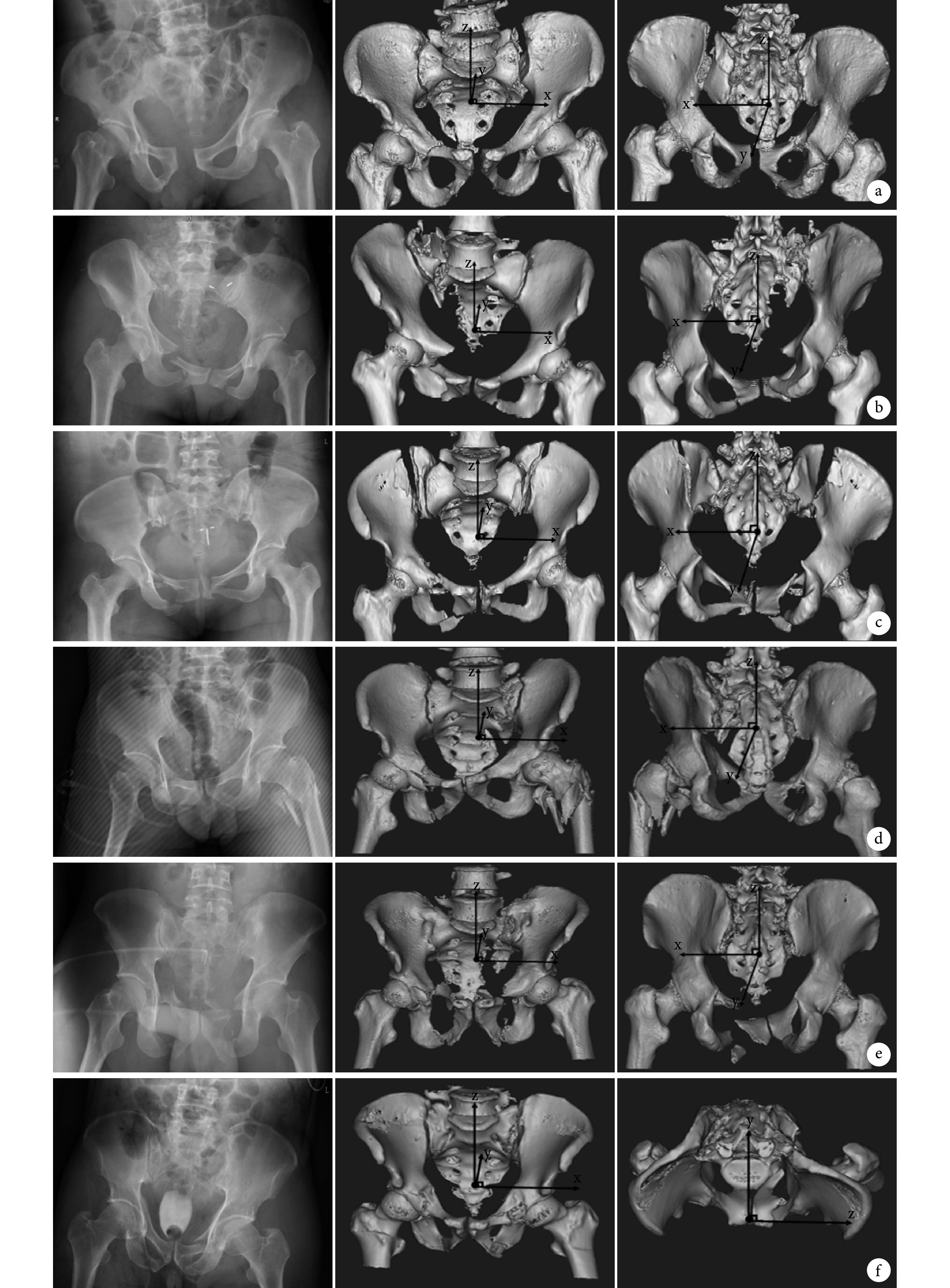
图 3.
Typical cases of three-dimensional displacement of pelvic fractures based on three-axis coordinate system
基于骨盆三轴坐标系的临床骨盆骨折三维移位方式
从左至右依次为骨盆正位 X 线片、三轴坐标系骨盆三维重建前面观、三轴坐标系骨盆三维重建后面观或上面观 a. x+移位;b. z+移位;c. z 旋–移位;d. y 旋+移位;e. x+、z+移位;f. y–、z 旋–移位
From left to right for anteroposterior X-ray film of pelvic, the front view of three-dimensional reconstruction pelvic of three-axis coordinate system, the back view or top view of three-dimensional reconstruction pelvic of three-axis coordinate system a. x+ displacement; b. z+ displacement; c. z rotation –; d. y rotation +; e. x+ z+ displacement; f. y– displacement, z rotation –
1.5. 骨盆骨折复位基本原则
根据确定的三轴移位方式分类,沿骨盆骨折移位方向的反方向进行复位,是我们确定的骨盆骨折复位基本原则。复位过程中可加以拔伸、牵引、撬拨等骨科常规复位手法,辅以 Schantz 钉、钉棒、骨钩等器械辅助进行复位。
1.6. 临床应用
1.6.1 一般资料 本组男 29 例,女 26 例;年龄 11~66 岁,平均 35.6 岁。致伤原因:交通事故伤 23 例,高处坠落伤 19 例,重物砸伤 11 例,地震伤 1 例,摔伤 1 例。Tile 分型:B2 型 3 例,B3 型 6 例,C1 型 30 例,C2 型 5 例,C3 型 11 例。合并四肢骨折 27 例,胸部损伤 21 例,颅脑损伤 15 例,脊柱骨折 17 例,腹腔脏器损伤 7 例,骶丛神经损伤 7 例,失血性休克 6 例,泌尿系损伤 4 例,四肢烧伤 1 例。根据上述方法,本组骨盆骨折患者 x、y、z 轴距离移位 11 例,旋转移位 21 例,距离合并旋转移位 23 例。
1.6.2 手术方法 根据上述骨盆骨折复位基本原则,本组 44 例在导航下行闭合复位(37 例)或有限切开复位(7 例)经皮空心钉内固定治疗骨盆骨折,其中 3 例同时行骨盆外固定支架固定术,4 例联合前环切开复位钢板螺钉内固定术;其余患者中,9 例单纯行切开复位重建钢板螺钉内固定,1 例切开复位经后路行双侧髂骨后嵴间张力带钢板固定术,1 例闭合复位骨盆外固定支架固定。共植入螺钉 105 枚(骶髂螺钉 58 枚、耻骨螺钉 44 枚、髂骨螺钉 3 枚),放置钢板 34 块(骶髂钢板 6 块、耻骨 14 块、髂骨钢板 14 块)。
1.6.3 评估指标 记录患者手术切口长度、复位时间、受辐射时间、螺钉植入时间及植入准确率、术中失血量、手术时间、住院时间,神经、血管、脏器损伤情况,术后骨折复位情况及术后并发症等。采用 Matta 评分标准(骨折移位≤4 mm 为优,4~10 mm 为良,10~20 mm 为可,>20 mm 为差),根据术后 X 线片评估患者骨折复位质量,评估该三轴移位方式应用于临床的疗效。
2. 结果
本组患者手术切口长度 3~20 cm,平均 7.1 cm;复位时间 1~50 min,平均 12.2 min;受辐射时间 6~120 s,平均 55.3 s;螺钉植入时间 4~117 min,平均 27.2 min,术后骨盆 X 线片或三维 CT 显示所有骨盆骨折复位良好,螺钉钢板植入无误;术中失血量 10~1 500 mL,平均 96.5 mL;手术时间 1~5 h,平均 2.1 h;住院时间 8~49 d,平均 18.7 d。本组患者均获随访,随访时间 6~53 个月,平均 16.7 个月。术后无其他脏器损伤;1 例发生医源性坐骨神经不全性牵伸损伤,术后 6 个月恢复;1 例手术创面感染,经反复换药抗感染后治愈;1 例因双肺挫伤伴肺部感染转入重症监护室,经治疗后顺利出院;2 例术后出现下肢深静脉血栓形成,经药物治疗 3 个月后症状完全消失。末次随访时根据 Matta 评分标准,优 39 例,良 13 例,可 3 例,优良率 94.55%。见图 4。
图 4.
Intraoperative reduction guidance of pelvic fractures according to the three-dimensional displacement classification of pelvic fracture and its reduction principles
根据三维移位方式分析结果术中指导复位
从左至右依次为三轴坐标系骨盆前面观、复位过程、术后骨盆正位 X 线片 a. x+移位;b. z+移位;c. z 旋+移位;d. y 旋+移位;e. y+、z+移位;f. x+、z+移位
From left to right for the front view of pelvic of three-axis coordinate system, reduction process, postoperative anteroposterior X-ray film of pelvic a. x+ displacement; b. z+ displacement; c. z rotation +; d. y rotation +; e. y+ z+ displacement; f. x+ z+ displacement

3. 讨论
骨盆骨折是一种较常见的多发性创伤,多由交通事故、高处坠落、重物压砸或机器事故等高能量损伤导致,病死率可达 5.1%~22.3%[4]。既往骨盆骨折多采用保守治疗,但常因骨盆骨折复位不佳造成骨盆畸形愈合、肢体短缩、慢性腰背痛甚至跛行等并发症。因此,对于骨盆骨折,尤其是不稳定骨盆骨折,了解其移位方式,进而早期精确复位和稳定固定,对维持血流动力学稳定、降低死亡率及改善预后至关重要。
本研究确定的三轴骨盆骨折移位方式分类是为了指导骨盆骨折术中复位,利用骨盆三维重建图片结合三维坐标系,进行骨盆骨折距离和旋转移位的分析。在骨盆三维重建图片中,建立以髂前下棘中点为原点的三维立体坐标系,就可只通过每个方向轴的距离和旋转确定其移位方式,进而按照沿着骨盆骨折移位方向的反方向进行复位,尤其适用于手术导航的引导下微创复位内固定,缩小了复位及辐射时间,便于骨盆骨折的精确复位和固定,本组末次随访时 Matta 评分标准优良率达 94.55%。
目前国内外医生关于骨盆坐标轴,尤其是坐标原点位置的确立争议颇多。陈惟昌等[5]确定的人体坐标系统,将耻骨联合上缘中点定义为坐标系原点,虽然定位容易,标志明显,可将重要结构与器官区分开,但其确定的是整个人体的坐标系,适合应用针对整个人体为对象时的定位定性诊断、手术导航及放射定位。徐青镭等[6]将髋臼的中心为原点建立骨盆正交坐标系,并测定了骨性标志和周围肌肉附着点的坐标,坐标轴适用于研究髋关节的运动及其手术治疗的效果。Zheng[7]则将骶尾关节中心及耻骨联合上缘的连线与两髋臼中心连线的交点定为原点,常用于测量髋关节置换术中髋臼的大小。而 Borhani 等[8]在研究骨盆旋转度及倾斜度时,将骨盆髂前上棘中点确定为原点,并证明方法可重复性强,操作简便。但我们通过建立的均值骨盆三维模型发现,髂前上棘中点在骨盆重心的偏外上方向,距离骨盆重心较远,为 48.15 mm;而髂前下棘中点位置逼近骨盆重心,距离仅为 24.53 mm,在骨盆各标记物中距离重心最近。若将髂前下棘中点设置为骨盆原点,可简化移位分析系统,并可重复、快速地应用于骨盆倾斜度及旋转度的评估,以及临床的定位定量诊断和手术导航。因此我们在骨盆三维重建正位片中将髂前下棘中点确定为原点。
近几年,随着骨盆骨折微创化治疗的发展和对骨盆骨折复位的日趋重视,逐渐有骨科研究者加入到骨盆骨折三维移位方式的研究中来。高金华等[9]的骨盆骨折 3D 分型是基于骨盆骨折 X 线片及三维重建图片,通过对骨盆两侧髂骨和坐骨结节等宽度、高度的对比,利用常规测量来判断移位,将骨盆骨折分为 1D、2D 和 3D 三类共 17 项分型。该分型也是一种空间分型,能够较为准确地表示骨折的各向移位,作者通过尸体解剖标本建立骨盆模型进行验证,Kappa 值显示为中等可信度。石成弟等[10]则根据骨盆 X 线片及 PACS 影像系统来诊断不稳定型骨盆骨折三维空间的移位,利用 PACS 自带工具测量健侧与患侧骨盆髂骨翼宽度、半骨盆上下径、耻骨结节及坐骨结节的移位幅度、闭孔面积等。通过比较分析,将不稳定骨盆骨折分为平面旋转(外翻与内翻)、矢状面旋转(前旋与后旋)和垂直上移。该移位分析简单实用,尤其适用于单侧骨盆骨折,作者通过 43 例临床病例行骨盆前后环空心螺钉内固定术进行验证,证实其可指导术中闭合复位,取得较为满意的复位效果。
因为骨盆解剖的复杂、深在及其骨折构型的多样性,加上各种伪影、遮挡、体位等的相互影响,使得传统根据 X 线片确定其移位及旋转方向非常困难,更无法进行术中指导复位。但随着 CT 及三维重建数字影像的发展,通过三维骨盆模型可以动态、清晰地显示骨盆骨折的位置、损伤时移位及旋转方向,且能模拟骨盆骨折的复位过程。本研究区别于传统的骨盆骨折移位分型,将临床问题与三维坐标系有效结合。通过对 21 例正常骨盆 CT 的点云数据进行均值化,逆向处理后建立了均值骨盆三维模型;为简化移位分析系统,创新性地将逼近骨盆重心的髂前下棘中点确定为骨盆原点,建立骨盆坐标系,在骨盆骨折三维重建图片上进行三轴空间移位方式研究,将复杂的骨盆骨折分解成三个坐标轴的距离移位及旋转移位,将所有骨折都标准化一致化,做到简单、精确、清晰,三维可视性和可重复性强。根据三轴移位分析建立了反移位方向复位的复位原则,并应用于临床骨盆骨折的手术复位,具有手术切口小、操作简便、复位速度快、准确率高、手术时间短、术中辐射时间少、术后并发症少及术后骨盆功能恢复良好等优点,取得了不错的复位及预后效果,具有一定的临床指导价值。
Funding Statement
国家自然科学基金资助项目(31370984、81501879);四川省科技厅国际合作项目(2015HH0049);AO Asia Pacific研究基金会资助项目(AOTAP16-07)
National Natural Science Foundation of China (31370984, 81501879); International Cooperation Project of Sichuan Provincial Science and Technology Department (2015HH0049); AO Asia Pacific Research Grants (AOTAP16-07)
References
- 1.Wong JM, Bucknill A. Fractures of the pelvic ring. Injury, 2017, 48(4): 795-802.
- 2.Pohlemann T, Stengel D, Tosounidis G, et al Survival trends and predictors of mortality in severe pelvic trauma: estimates from the German Pelvic Trauma Registry Initiative. Injury. 2011;42(10):997–1002. doi: 10.1016/j.injury.2011.03.053. [DOI] [PubMed] [Google Scholar]
- 3.Balogh Z, King KL, Mackay P, et al The epidemiology of pelvic ring fractures: a population-based study. J Trauma. 2007;63(5):1066–1073. doi: 10.1097/TA.0b013e3181589fa4. [DOI] [PubMed] [Google Scholar]
- 4.Yoshihara H, Yoneoka D Demographic epidemiology of unstable pelvic fracture in the United States from 2000 to 2009: trends and in-hospital mortality. J Trauma Acute Care Surg. 2014;76(2):380–385. doi: 10.1097/TA.0b013e3182ab0cde. [DOI] [PubMed] [Google Scholar]
- 5.陈惟昌, 陈志华, 赵天德, 等 可视化人体的整体坐标系统. Ct 理论与应用研究. 2004;13(1):1–6. [Google Scholar]
- 6.徐青镭, 倪卫明, 万年宇 人体髋关节周围肌肉三维生物力学模型的建立与应用. 伤残医学杂志. 2003;11(3):13–14. [Google Scholar]
- 7.Zheng G Assessing the accuracy factors in the determination of postoperative acetabular cup orientation using hybrid 2D-3D registration. J Digit Imaging. 2010;23(6):769–779. doi: 10.1007/s10278-009-9226-4. [DOI] [PMC free article] [PubMed] [Google Scholar]
- 8.Borhani M, Mcgregor AH, Bull AM An alternative technical marker set for the pelvis is more repeatable than the standard pelvic marker set. Gait Posture. 2013;38(4):1032–1037. doi: 10.1016/j.gaitpost.2013.05.019. [DOI] [PMC free article] [PubMed] [Google Scholar]
- 9.高金华, 郭晓山, 梁清宇, 等 基于 X 线片与 CT 的不稳定型骨盆骨折 3D 分型研究. 中华创伤骨科杂志. 2013;15(11):961–966. [Google Scholar]
- 10.石成弟, 胡炜, 余可和, 等 不稳定型骨盆骨折三维空间移位的 X 线诊断方法及其在闭合复位术中的初步应用. 中华创伤杂志. 2013;29(8):717–722. [Google Scholar]