Abstract
This paper describes the design, fabrication and testing of a wireless bladder pressure sensing system for chronic, point-of-care applications such as urodynamics or closed-loop neuromodulation. The system consists of a miniature implantable device and an external RF receiver and wireless battery charger. The implant is small enough to be cystoscopically implanted within the bladder wall, where it is securely held and shielded from the urine stream. The implant consists of a custom application-specific integrated circuit (ASIC), a pressure transducer, a rechargeable battery, and wireless telemetry and recharging antennas. The ASIC includes instrumentation, wireless transmission, and power-management circuitry and on average draws less than 9 μA from the 3.6-V battery. The battery charge can be wirelessly replenished with daily 6-hour recharge periods that can occur during periods of sleep. Acute in vivo evaluation of the pressure-sensing system in canine models has demonstrated that the system can accurately capture lumen pressure from a submucosal implant location.
Index Terms—: Bladder pressure, implantable biomedical device, low-power implantable device, micromanometer, wireless implant, wireless recharging
I. Introduction
Clinical disciplines involving the cardiovascular, respiratory, gastrointestinal and urological systems typically require measurement of physiological pressures as an aid to medical diagnosis and monitoring. Besides blood pressure, many physiological pressures are measured invasively with catheters or similar devices which tether the patient to cumbersome external equipment and present risk of infection. Urodynamics is one of the most common urological point-of-care techniques but can be problematic in chronic applications such as neurostimulation in bladder rehabilitation because at present it requires catheterization.
Cather-based urodynamics, used to diagnose urinary incontinence, is considered unreliable because it can be difficult to accurately reproduce symptomatic leakage in a clinical setting [1–3]. Some urologists instead diagnose and treat incontinence based solely on patient reporting of symptoms [4]. Long-term physiological confirmation of patient complaints in an ambulatory environment cannot presently be achieved, but would lead to more precise diagnoses and treatments with higher success rates.
Implantable pulse generators such as the Medtronic InterStim® can effectively treat conditions such as overactive bladder through continuous stimulation of the sacral nerve [5]. This method of stimulation inhibits involuntary bladder contractions but habituation to the continuous stimulation may require occasional modification of the stimulation parameters to maintain efficacy. An implantable bladder pressure monitor could provide closed-loop pressure feedback to a next-generation conditional stimulation device. Conditional neurostimulation applied only at the onset of an involuntary contraction has been shown to be more effective than open-loop continuous stimulation, resulting in greater bladder capacity, and using less power [6].
A wireless, implanted bladder pressure sensor could send pressure telemetry to an external receiver (Fig. 1). Several existing biomedical implants are small enough for this application, but they operate at only a shallow implantation depth [7], or do not support real-time monitoring [8]. Bladder pressure sensors have been developed as described in [9], but are relatively large and are not well-suited for a chronic, ambulatory application. To provide chronic, wireless bladder pressure monitoring in ambulatory patients, a wireless, implantable micro-manometer (WIMM) system was proposed for long-term applications [10], such as to provide feedback for neuromodulation bladder control devices.
Fig. 1.
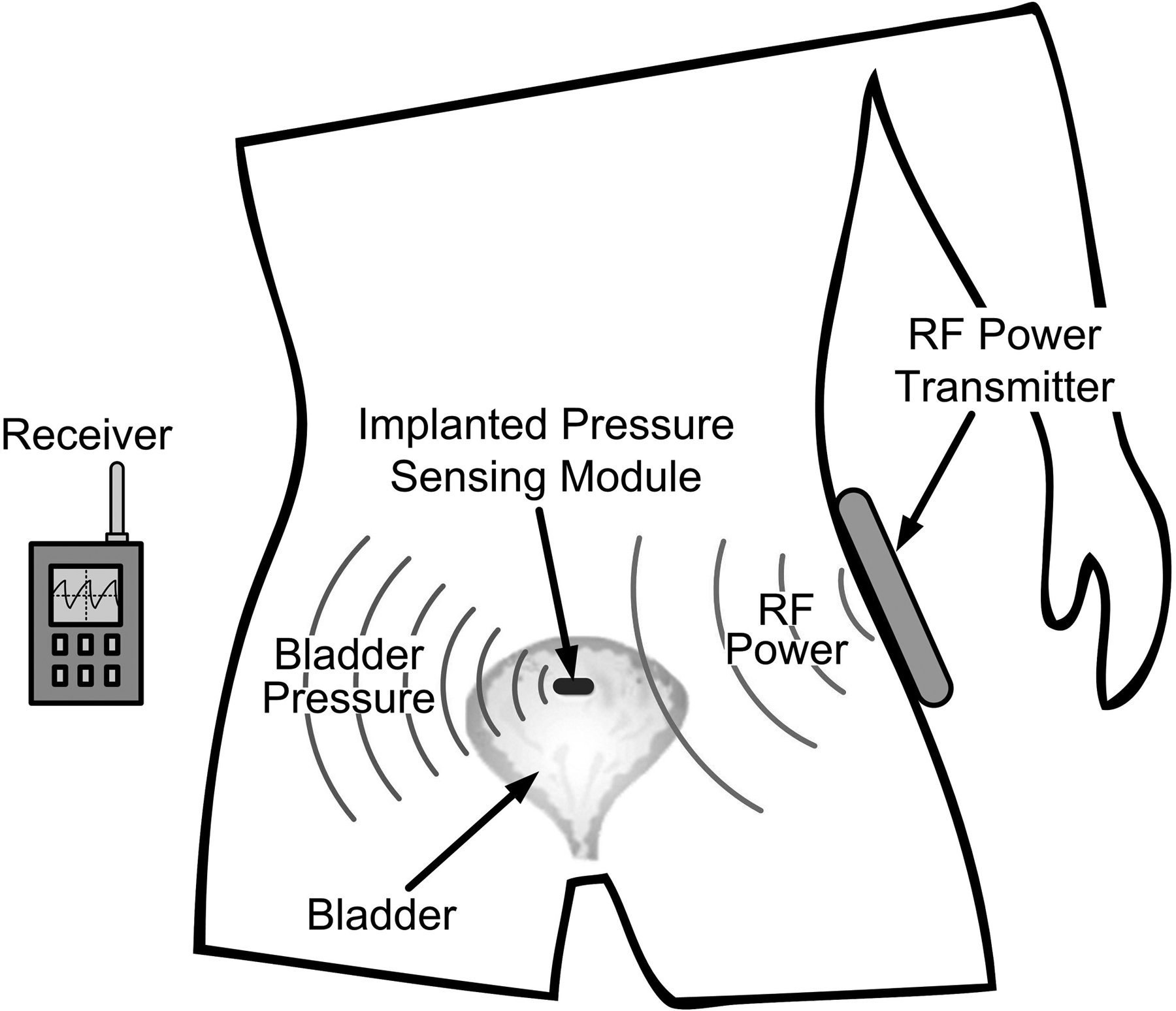
Conceptual drawing of the wireless implantable micro-manometer (WIMM) within the human bladder. Pressure telemetry is wirelessly transmitted to an external receiver, and an external RF recharge unit periodically restores the charge on the implant micro-battery.
II. Wireless Implant System Design
The WIMM implantable component of the system was designed specifically for use in the bladder, and the physical characteristics of the bladder as well as common surgical methods largely determined the implant function and size. The WIMM design initially focused on the implantation site and method, and several surgical consultations confirmed the feasibility of implanting a device within the bladder.
Maintaining a pressure-sensing device within the bladder is not a simple task because foreign objects located chronically within the bladder lumen are subject to mineral encrustation (which can lead to stone formation) and expulsion during urination. An ideal location for a pressure-sensing implant is beneath the bladder mucosa, a self-regenerating, compliant tissue that lines the inner wall of the organ. An implant may be introduced into the bladder using conventional urological tools such as cystoscopes and implanted in a submucosal pocket. After healing, the mucosal layer is strong enough to securely retain the sensor, and lumen pressure can accurately be measured through the urothelium.
Clinical Requirements
Because the mucosa is thin and a minimally invasive cystoscopic surgery is desirable, the WIMM implant was designed according to strict size constraints. A flattened or ovoid form factor facilitates placement beneath the mucosa and the maximum device width is limited by cystoscope dimensions. After discussion with urological surgeons and clinicians it was determined that a capsule measuring 7 mm wide by 4 mm thick by 15 mm long would be sufficiently small for the desired implantation site and method.
Because of the deep location of the bladder and obesity factors, the distance between the implant and the external transmitter could be as large as 30 centimeters. Continuous RF powering is impractical at this distance, as it would require a powerful external transmitter which would likely exceed patient safety limits and certainly reduce patient mobility, negating the positive effects of a catheter-free system.
Implant Architecture
Instead of continuous RF powering, the proposed WIMM implant runs primarily from a micro-battery and RF-recharge would occur during 6-hour periods, e.g. when the user is sleeping. The battery and associated recharge inductor consume more than half of the system volume.
Other components of the WIMM implant must be highly integrated to satisfy volume constraints. A simplified block diagram of the WIMM bladder pressure sensing system consists of an implanted device and an external RF receiver-recharger (Fig. 2). The WIMM implant has three main components: a Quallion micro-battery (QL003I), a MEMS pressure transducer (SiMicro SM5112), and a custom, application-specific integrated circuit (ASIC). The ASIC incorporates circuitry which can broadly be categorized as instrumentation, wireless transmission, and power control. The external receiver-recharger uses inductive antennas to receive pressure telemetry from the implant and to send power and commands to the implanted battery recharge circuits. During normal operation, the receiver is portable and battery powered, but wireless recharging requires AC line power.
Fig. 2.
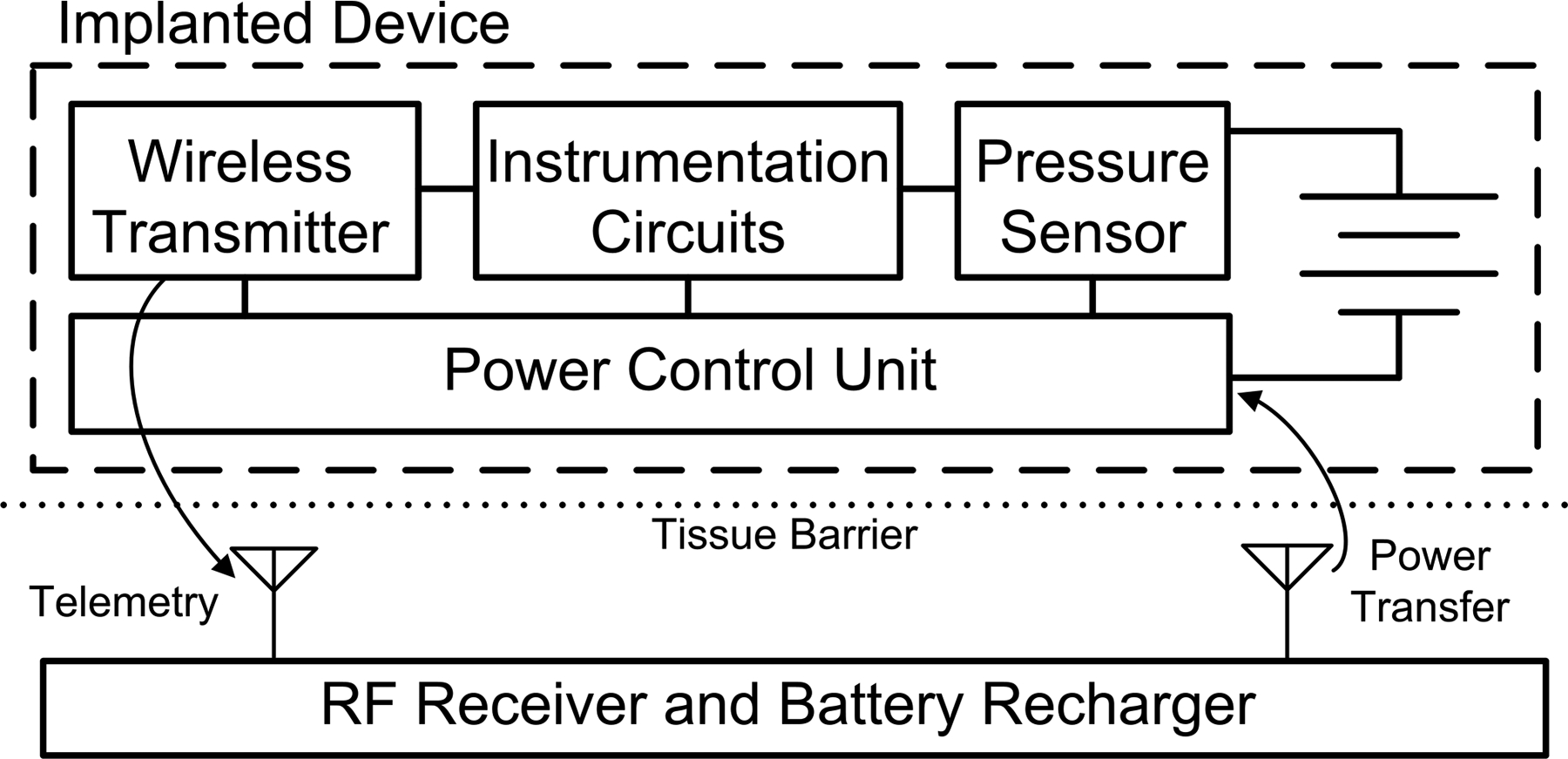
Block diagram of the WIMM system. The implanted device consists of a micro-battery, pressure transducer, and ASIC with instrumentation, telemetry, and power management circuitry. An external RF receiver/recharger receives pressure telemetry and intermittently recharges the implanted micro-battery.
Instrumentation Circuitry
The core of the WIMM implant is an ASIC with instrumentation, telemetry, and power management circuits. The instrumentation circuits use low-noise, low-power CMOS design techniques to amplify the piezoresistive pressure sensor signal and produce digitized samples. The instrumentation circuitry covers a pressure range of 0–250 cm H2O and provides a resolution better than 1 cm H2O. This pressure range is physiologically reasonable within the bladder, and the resolution is sufficient for urological diagnosis and neuromodulation feedback.
Wireless Telemetry
The WIMM ASIC also incorporates a wireless frequency-shift-keyed (FSK) transmitter that sends digital pressure samples to the external receiver-recharger. The transmitter is a cross-coupled LC tank oscillator that operates in the unlicensed 27.12-MHz industrial-scientific-medical (ISM) band. The small off-chip inductor that is part of the tank oscillator also functions as the transmitting antenna for near-field communication.
Power Control Unit
The implanted battery has a capacity of about 3 milliamp-hours (mAh), so power management is critical to the success of the WIMM implant in chronic applications. A 6-hour recharge session can replenish 0.6 mAh of capacity and the WIMM implant is intended to run for at least 48 hours between charges. This implies that the time-averaged current consumption for the WIMM implant must be less than about 12 microamps.
Achieving such a small current draw for a continuously running implantable telemetry system is not feasible, but the ASIC power-control unit (PCU) leverages the speed ratio between bladder pressure changes and the instrumentation capability. Bladder pressure need be sampled at a rate of just 10 Hz, even though instrumentation and telemetry circuits can provide sample rates several thousand times faster. The PCU is a suite of very low power circuits that are always running in the background but sequentially turn on and off the vital instrumentation and telemetry circuits such that ten samples are transmitted each second.
The power distribution is dominated by the piezoresistive transducer, and the implant consumes over 1 mA from the battery (Fig. 3a). With the PCU activated the time-averaged current is less than 9 μA and the power consumption of the transducer and instrumentation and telemetry circuits is greatly reduced (Fig. 3b).
Fig. 3.
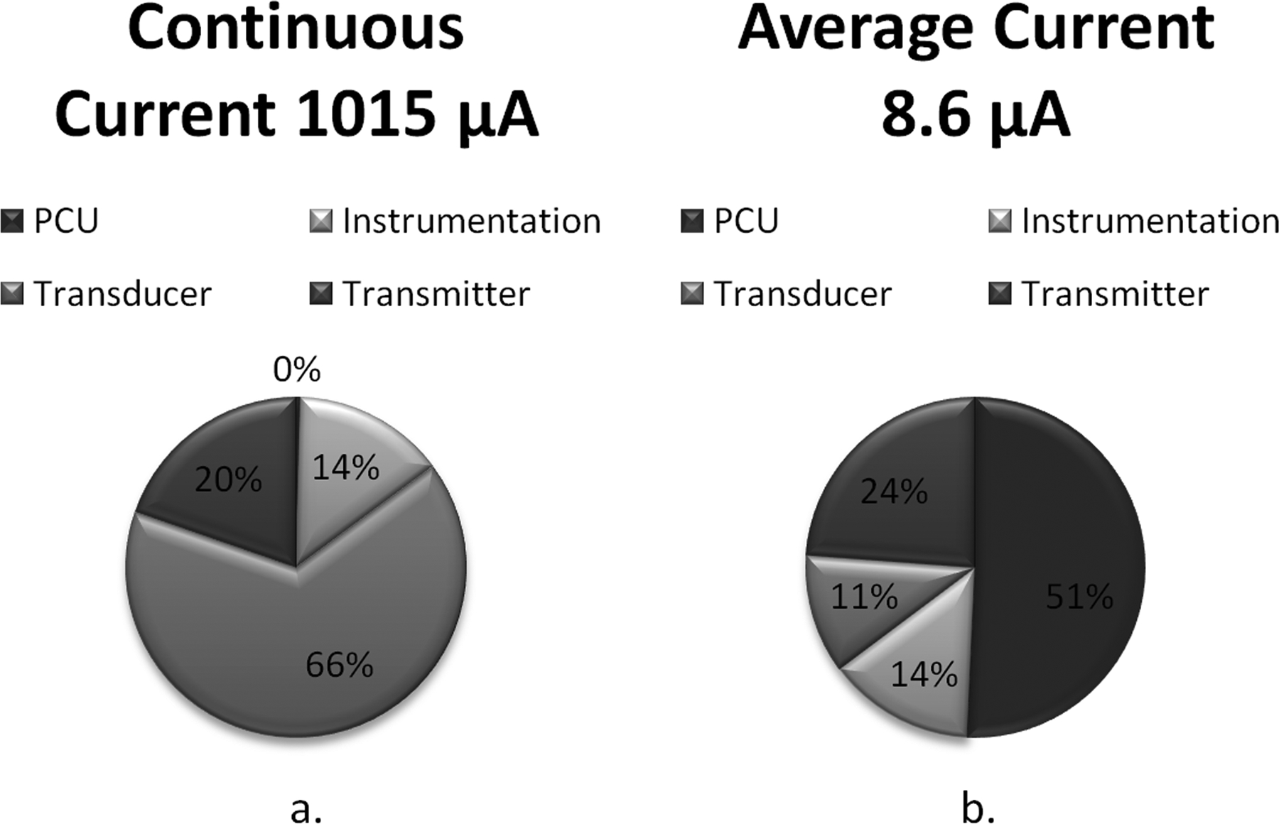
Illustration of calculated WIMM current consumption a) without and b) with the power control unit (PCU). Without the PCU, the peak current draw is over 1 mA. With the PCU, the peak current remains unchanged but the time-averaged current is greatly reduced by the low-duty-cycle operation
External RF Receiver-Recharger
Besides the implantable device, the WIMM bladder pressure sensing system consists of an external wireless receiver and battery recharger. The receiver section is a small and portable 27.12-MHz FSK receiver that uses a complex programmable logic device (CPLD) to recover and reconstruct the telemetry from the implant. The wireless recharger consists of a Class-E resonant amplifier which produces a powerful magnetic field at 3 MHz. The implanted ASIC contains circuits which can harvest DC current from the field and use it to recharge the implanted battery.
III. Implant Fabrication and Packaging
The WIMM ASIC was fabricated in the OnSemi 0.5-μm process and was fully bench tested before being incorporated in a prototype implant suitable for acute animal studies. The prototype implant consisted of the ASIC, an SM5112 pressure transducer, a small printed-circuit board (PCB), and several passive devices. The micro-battery was not included in initial prototypes due to its expense, but was separately packaged and tested as described in [11].
The ASIC and SM5112 sensor were wire-bonded to the PCB and encapsulated using Hysol FP4450 epoxy. Passive devices such as the transmitting inductor were soldered to the PCB, and the entire board was coated in epoxy.
The implantable device was coated in several thin films of silicone to provide watertight protection during acute implantations. Prior to the encapsulation step, a polypropylene ring was secured around the transducer, and the ring cavity was filled with an incompressible silicone gel. Next, a silicone/nylon mesh membrane was glued around the edges of the ring and silicone encapsulant was applied to the rest of the implant except for the membrane, which was left uncoated. This encapsulation method produced a watertight implant with a low-attenuation pressure “window,” as shown in Fig. 4.
Fig. 4.
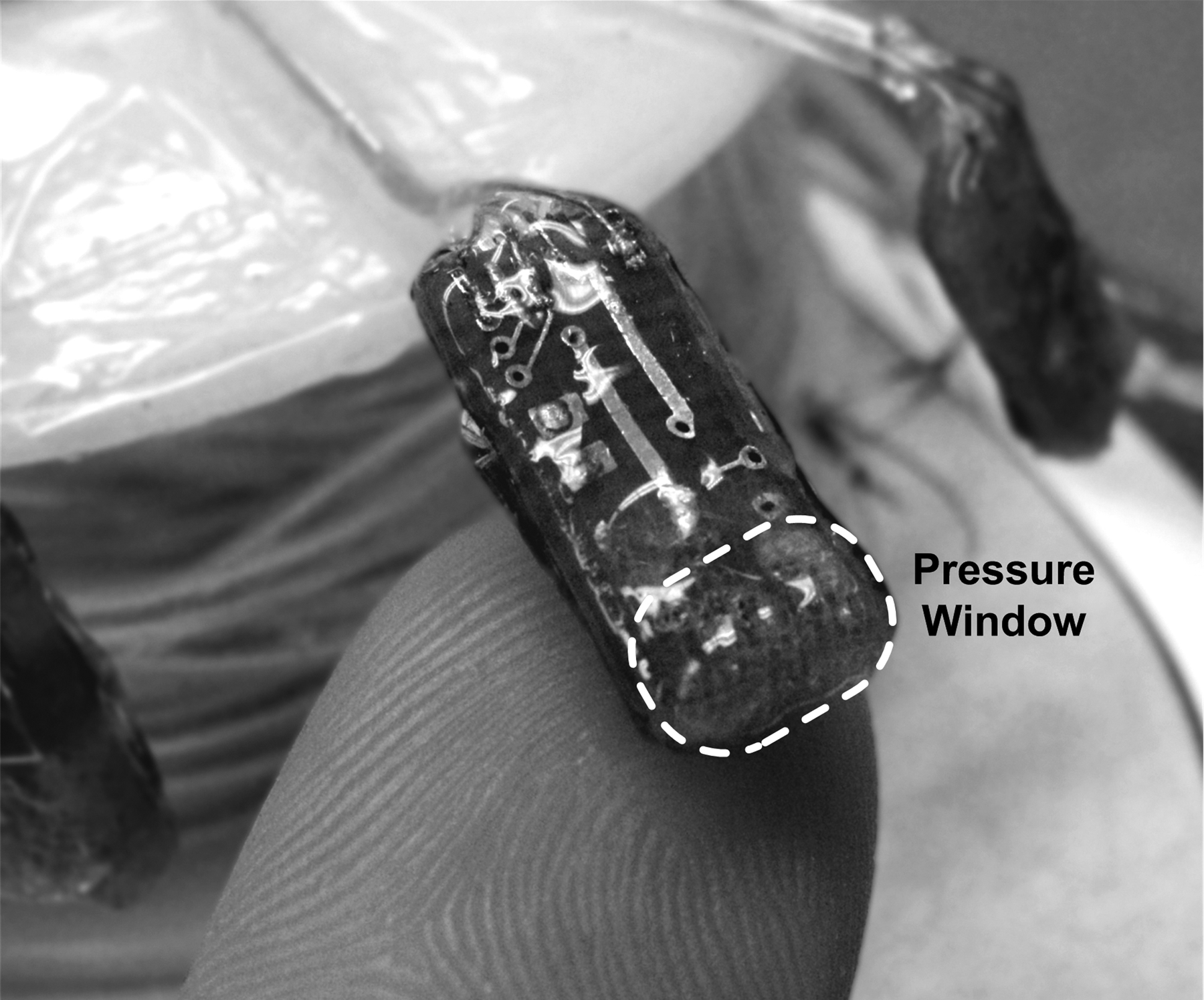
Encapsulated WIMM implant ready for in vivo experimentation (finger shown for size reference). The pressure window formed by a nylon/silicone membrane over silicone gel is highlighted for clarity.
IV. In vivo demonstration and results
The encapsulated WIMM implant was initially characterized in a water-filled pressure chamber and later in several excised pig bladders which were maintained in a bath of Tyrode’s solution. These controlled environments were used to confirm the linearity and sensitivity of the transmitted pressure readings. The pressure port and mucosal lining attenuated the measured pressure and a resulting sensitivity of 2.7 cm H2O was achieved. This resolution is sufficient for urological diagnosis where clinicians typically use pattern recognition to analyze the relative pressure waveforms. After the initial characterization, the WIMM implant was tested in vivo using anesthetized canine models. Dorsal nerve stimulation electrodes were surgically inserted to trigger bladder contractions. The implant surgery was not performed cystoscopically as intended for eventual clinical use due to the animal’s smaller urethra. Instead, an abdominal incision was made to expose the bladder. A shallow incision was made into the bladder wall such that the mucosa lining was left intact, and the WIMM implant was inserted therein (Fig. 5a.) and secured with sutures (Fig. 5b.). This implantation method allowed for wires to protrude from the bladder and the Quallion battery was not implanted.
Fig. 5.

Photographs of the WIMM implant a) being surgically implanted within a canine bladder and b) after implantation within the bladder wall. The incision was sutured shut with power wires protruding from the bladder
Bladder pressure readings from the WIMM implant and a reference microtip catheter in the bladder lumen were simultaneously captured with a data acquisition system. A 10-second sample recording is presented in Fig. 6. This sample recording is a portion of a much larger recording that is several hours long. The lumen reference catheter is the upper trace, and the lower trace is reconstructed from WIMM digital samples. A 1 Hz lowpass filter was applied to both signals and a correlation coefficient of r=0.88 was obtained. The deviation in measured pressure versus the reference is probably due to the device interface with the tissue.
Fig. 6.

Bladder pressure traces obtained from in vivo experiment with canine model. The reference microtip catheter lumen pressure trace (upper graph) correlates well with the submucosal pressures obtained from the WIMM implant (lower graph).
The FSK transmitter signal strength of the WIMM implant was tested at various antenna orientations and spacings during the in vivo studies. A received spectrum is shown in Fig. 7. This spectrum was obtained by holding the receiving antenna 10 cm away from, and on-axis with, the implant. The spectrum has the typical FSK dual-tone signature and the received level is about −85 dBm, which is sufficient for reception by the external receiver.
Fig. 7.
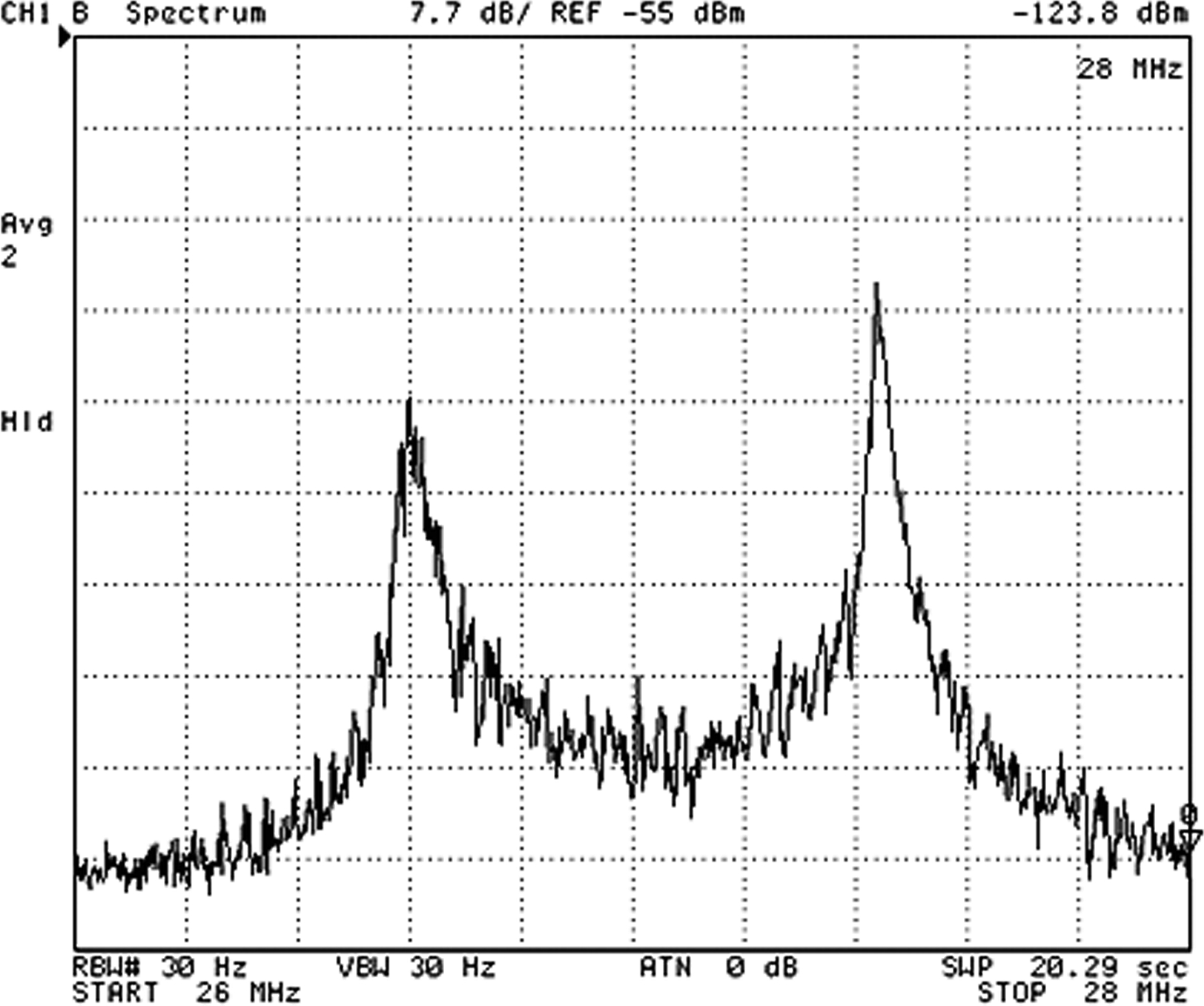
FSK spectrum of the signal received from the WIMM implanted in a canine bladder with antenna separation of 10 cm.
V. Conclusion
The WIMM bladder pressure sensing system has been designed, fabricated, and tested in vivo using a canine model. The submucosal pressure readings correlate well with the simultaneous bladder lumen pressure, indicating the feasibility of the submucosa as a novel sensor implantation site. A wireless pressure sensor implanted thus could facilitate chronic urodynamics studies and provide bladder pressure feedback to enhance neurostimulator device therapies and their outcomes.
VI. Acknowledgment
The authors would like to thank the contributions of Dr. Hui Zhu of the Louis Stokes VA Medical Center and Drs. Kenneth J. Gustafson and Adam Boger of the Dept. of Biomedical Engineering, Case Western Reserve University.
This work was supported by the Rehabilitation Research Service of the U.S. Department of Veterans Affairs.
Contributor Information
Steve J. A. Majerus, Department of EECS, Case Western Reserve University, Cleveland, OH 44106 USA (phone: 216-368-0398; fax: 216-707-6420.
Paul C. Fletter, Advanced Platform Technology (APT) Center, Louis Stokes Cleveland VA Medical Center (LSCVAMC), Cleveland, OH 44106 USA..
Margot S. Damaser, APT Center at the LSCVAMC, Cleveland, OH 44106 and the Cleveland Clinic, Cleveland, OH 44195 USA..
Steven L. Garverick, Department of EECS, Case Western Reserve University, Cleveland, OH 44106 USA. He is currently with the West Wireless Health Institute, La Jolla, CA 92037, USA..
References
- [1].Gupta A, Defreitas G, and Lemack GE, “The reproducibility of urodynamic findings in healthy female volunteers: results of repeated studies in the same setting and after short-term follow-up.” Neurourology & Urodynamics, vol. 23, pp. 311–316, 2004. [DOI] [PubMed] [Google Scholar]
- [2].Rovner ES and Wein AJ, “Evaluation of lower urinary tract symptoms in females.” Current Opinion in Urology, vol. 13, pp.273–278, July. 2003. [DOI] [PubMed] [Google Scholar]
- [3].Scaldazza CV and Morosetti C, “Effect of different sized transurethral catheters on pressure-flow studies in women with lower urinary tract symptoms.” Urologia Internationalis, vol. 75, pp. 21–25, 2005. [DOI] [PubMed] [Google Scholar]
- [4].Chapple CR, “Primer: questionnaires versus urodynamics in the evaluation of lower urinary tract dysfunction- one, both or none?” Nature Clinical Practice Urology, vol. 2, pp. 555–564, November. 2005. [DOI] [PubMed] [Google Scholar]
- [5].Siegel SW et al. “Long-term results of a multicenter study on sacral nerve stimulation for treatment of urinary urge incontinence, urgency-frequency, and retention.” Urology, Vol. 56, No. 6, Sup.1, pp. 87–91, December. 2000. [DOI] [PubMed] [Google Scholar]
- [6].Kirkham AP, Shah NC, Knight SL, Shah PJ, and Craggs MD, “The acute effects of continuous and conditional neuromodulation on the bladder in spinal cord injury.” Spinal Cord, vol.39, pp.420–428, 2001. [DOI] [PubMed] [Google Scholar]
- [7].Cong P, Ko WH, Young DJ, “Wireless batteryless implantable blood pressure monitoring microsystem for small laboratory animals.” IEEE Sensors Journal, Vol. 10, No. 2, pp. 243–254, February 2010. [Google Scholar]
- [8].Chow EY et al. “Implantable wireless telemetry boards for in vivo transocular transmission.” IEEE Transactions on Microwave Theory and Techniques, Vol. 56, No. 12, pp. 3200–3208, 2008. [Google Scholar]
- [9].Wang CC et al. “A mini-invasive long-term bladder urine pressure measurement ASIC and system.” IEEE Transactions on Biomedical Circuits and Systems, vol. 2, No. 1, pp. 44–49, March. 2008. [DOI] [PubMed] [Google Scholar]
- [10].Fletter PC, et al. “Wireless ambulatory system for chronic bladder pressure monitoring.” Proceedings of INSS 2009, Pittsburgh, PA, USA, June 17–19, 2009. [Google Scholar]
- [11].Cong P, Suster MA, Chaimanonart N, Young DJ, “Wireless power recharging for implantable bladder pressure sensor.” IEEE Sensors 2009, Christcurch, New Zealand, pp. 1670–1673, October. 25–28 2009. [Google Scholar]


