Abstract
Purpose
We propose a novel compensator‐based IMRT system designed to provide a simple, reliable, and cost‐effective adjunct technology, with the goal of expanding global access to advanced radiotherapy techniques. The system would employ easily reusable tungsten bead compensators that operate independent of a gantry (e.g., mounted in a ring around the patient). Thereby the system can be retrofitted to existing linac and cobalt teletherapy units. This study explores the quality of treatment plans from the proposed system and the dependence on associated design parameters.
Methods
We considered 60Co‐based plans as the most challenging scenario for dosimetry and benchmarked them against clinical MLC‐based plans delivered on a linac. Treatment planning was performed in the Pinnacle treatment planning system with commissioning based on Monte Carlo simulations of compensated beams. 60Co‐compensator IMRT plans were generated for five patients with head‐and‐neck cancer and five with gynecological cancer and compared to respective IMRT plans using a 6 MV linac beam with an MLC. The dependence of dosimetric endpoints on compensator resolution, thickness, position, and number of beams was assessed. Dosimetric accuracy was validated by Monte Carlo simulations of dose distribution in a water phantom from beams with the IMRT plan compensators.
Results
The 60Co‐compensator plans had on average equivalent PTV coverage and somewhat inferior OAR sparing compared to the 6 MV‐MLC plans, but the differences in dosimetric endpoints were clinically acceptable. Calculated treatment times for head‐and‐neck plans were 7.6 ± 2.0 min vs 3.9 ± 0.8 min (6 MV‐MLC vs 60Co‐compensator) and for gynecological plans were 8.7 ± 3.1 min vs 4.3 ± 0.4 min. Plan quality was insensitive to most design parameters over much of the ranges studied, with no degradation found when the compensator resolution was finer than 6 mm, maximum thickness at least 2 tenth‐value‐layers, and more than five beams were used. Source‐to‐compensator distances of 53 and 63 cm resulted in very similar plan quality. Monte Carlo simulations suggest no increase in surface dose for the geometries considered here. Simulated dosimetric validation tests had median gamma pass rates of 97.6% for criteria of 3% (global)/3 mm with a 10% threshold.
Conclusions
The novel ring‐compensator IMRT system can produce plans of comparable quality to standard 6 MV‐MLC systems. Even when 60Co beams are used the plan quality is acceptable and treatment times are substantially reduced. 60Co‐compensator IMRT plans are adequately modeled in an existing commercial treatment planning system. These results motivate further development of this low‐cost adaptable technology with translation through clinical trials and deployment to expand the reach of IMRT in low‐ and middle‐income countries.
Keywords: 60‐cobalt, compensator, global oncology, IMRT
1. Introduction
Cancer is a major healthcare concern worldwide with 14.1 million cases in 20121 and 20 million new cases per year expected by 2025.2 Recent reports have suggested 5 of the 7 million cancer deaths yearly occur in low‐ and middle‐income countries (LMICs)3 and this number is expected to grow in part because of insufficient access to care.
One essential tool for managing cancer is radiation therapy (RT). RT is estimated to be indicated for 50% of cancer patients, either for curative or palliative purposes.4 A report from the International Atomic Energy Agency suggested that 60% of patients in the LMIC setting will require RT.5 In some disease sites which are over‐represented in LMICs, such as head‐and‐neck cancers, the ideal RT utilization rate may be nearly 80% of patients.4
The Global Task Force on Radiotherapy for Cancer Control has reported that in addition to the health benefits there are important economic benefits from RT in LMICs because of its cost‐effectiveness6 and its reduced risk of morbidity and mortality compared with available surgical and chemotherapy alternatives. Because of the challenges in managing such treatment toxicities in the LMIC setting, the impact of state‐of‐the art RT is expected to be high. These benefits have driven an urgent need for the availability of state‐of‐art IMRT capable radiotherapy technologies in LMICs.7
Achieving these health and economic benefits depends on the ability to limit the toxicities in normal tissues when delivering RT. A key to this is delivering highly conformal radiation dose distributions to the targets while simultaneously sparing normal tissues. The dose distributions enabled by IMRT can increase the quality of life of cancer patients by sparing more normal tissue and reduce costs associated with managing toxicities8. In head‐and‐neck cancer treatments, for example, IMRT can deliver high doses to the target region while protecting the parotid glands thus limiting the serious and costly toxicity of xerostomia (dry mouth) and dental caries.9
While IMRT is available in essentially every radiotherapy clinic in high‐income countries,10 such capabilities are largely absent due to the lacking technology in vast regions of LMICs. The current most widely used technology relies on multi‐leaf collimators (MLCs) composed of hundreds of moving parts, which need to be maintained to stringent mechanical tolerances. Such systems are often difficult to acquire and maintain in the LMIC environment. There can be substantial losses in efficiency especially when underlying infrastructure is not reliable.11
Here, we present a design for a novel IMRT system which obviates many of these problems and can be adapted to the RT delivery units already available in LMICs. The system relies on physical compensators in the beam path to modulate the intensity of the radiation beams instead of moving machine‐inherent MLCs. Compensators offer the following advantages: increased reliability, less downtime and repair, reduced requirements of quality assurance (QA) procedures, shorter treatment times compared to step‐and‐shoot IMRT, and less influence of patient motion during treatment. While physical compensators for IMRT are not new,12, 13, 14 the system proposed here has several novel features: (a) Patient‐specific compensators are not required to be manually exchanged between beams because unlike traditional compensators which are mounted sequentially on the treatment head, these are simultaneously mounted before treatment such as on a ring structure around the patient. This minimizes treatment time. (b) A ring may also be retrofitted to existing isocentric teletherapy units, allowing the addition of IMRT to a clinic without having to purchase a new treatment unit. (c) The compensators are plastic molds which are filled with metal before each treatment. This allows for the re‐use of attenuating material, reduces the cost and complexity of production, and enables local or regional production of molds.
The goal of this study is to assess the feasibility of the proposed device by studying the quality of radiation therapy plans and delivery times. We benchmark the device by comparing plan quality against existing MLC‐based devices. We also explore several key design parameters and their potential impact on plan quality. This serves as support for further development and for a future clinical trial to investigate the safety and efficacy of this compensator‐based IMRT system.
2. Materials and methods
2.A. Description of proposed system
An illustration of the ring concept is shown in Fig. 1. Compensators are mounted around the patient on a ring structure which is independent of the gantry. They are placed at evenly spaced beam angles, which are common among all patients. The gantry will move from compensator to compensator and deliver its rectangular fields through them. Design alternatives to the ring concept which accomplish the same objectives may be possible.
Figure 1.
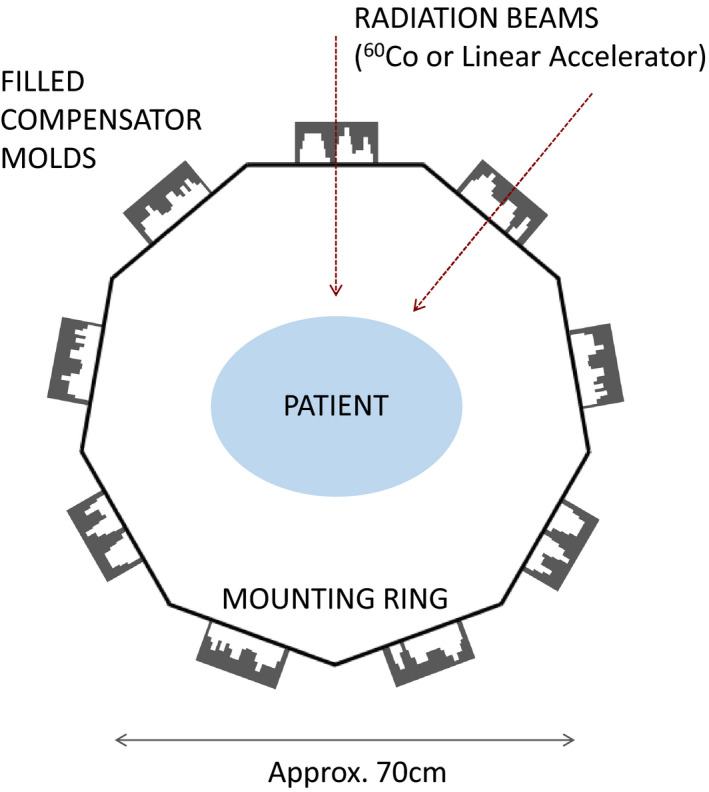
A ring‐based design of the proposed compensator system. Here nine compensators are placed in a ring 35 cm from the isocenter, for example. The gantry rotates around the ring and delivers each of the nine beams successively. [Color figure can be viewed at wileyonlinelibrary.com]
The compensators are plastic molds filled with attenuating material, nominally tungsten bead. A mold could be made from rectangular plastic sheets with the interior deformed into a concavity that is the shape of the desired compensator, which can then be filled level with attenuator. The plastic molds can be formed locally or at a regional site and transported to individual clinics. Production and transportation are simplified because the molds are lightweight plastic. A plastic mold filled with attenuator would constitute the compensator, mounted as a unit. After each treatment the attenuator could be emptied from the molds and re‐used from patient to patient. Reusing attenuator limits the required amount of compensator material on hand, which can be bulky and expensive. Solid brass or other metals would be much more expensive to machine and transport than plastic molds. Low‐melting‐point alloys are not being considered as an attenuator because of the time required to re‐melt and to form compensators between patients. The exact method of forming the molds is under development, and the maximum thickness of compensators is a matter of optimization discussed in Section 3.A.3.
The simulations and plans discussed here are for 60Co teletherapy beams used in combination with the compensator system. Beams from 60Co were selected because they are in wide use in LMICs and are expected to be the most challenging application for IMRT due to their unfavorable depth‐dose characteristics and large source sizes (~2 cm), which produce broad penumbras. If a 60Co‐compensator system is feasible then a linac‐compensator system is expected to provide IMRT of comparable or better quality.
2.B. Monte Carlo design study
A Monte Carlo study was performed to understand limitations and design tradeoffs. Once design parameters were set, these simulations produced commissioning data for the treatment planning study discussed in Section 2.C. Simulations were performed with the EGSnrc software package using the BEAMnrc and DOSXYZnrc user codes.15, 16 The Theratronics 780‐C was selected as a representative cobalt teletherapy machine, and a BEAMnrc model of it was adapted from the work of Dhanesar.17 The unit has a steel‐clad 60Co source of diameter 2 cm and height 2.8 cm. The source shielding and primary collimator are composed of tungsten and four sets lead trimmers extend down to 28 cm below the lower face of the source. These trimmers were set to a 35 × 35 cm field projected at 80 cm SAD, and phase space files were created from events collected on a scoring plane 30 cm below the source for use in later simulations.
2.B.1. Compensator penumbra
The compensators modulate the beam fluence in lieu of an MLC, and so define the penumbra most relevant to this system. Penumbra width is a critical performance consideration as it limits the dose gradients that are achievable with IMRT. Placing the compensator closer to the patient results in a sharper penumbra and thus more‐sharply modulated beams.
To study performance, a half‐beam‐block tungsten compensator 2.14 cm thick (one tenth‐value‐layer (TVL) for the primary beam) was placed in the beam path and its vertical position relative to a water phantom varied over multiple successive runs. Profiles were extracted at the level of isocenter 10 cm deep in water. The profiles and 80–20% penumbra widths are shown in Fig. 2. The 80–20% penumbra widths were extracted from a fit to an empirical model with constant, linear, and sigmoidal components.
Figure 2.
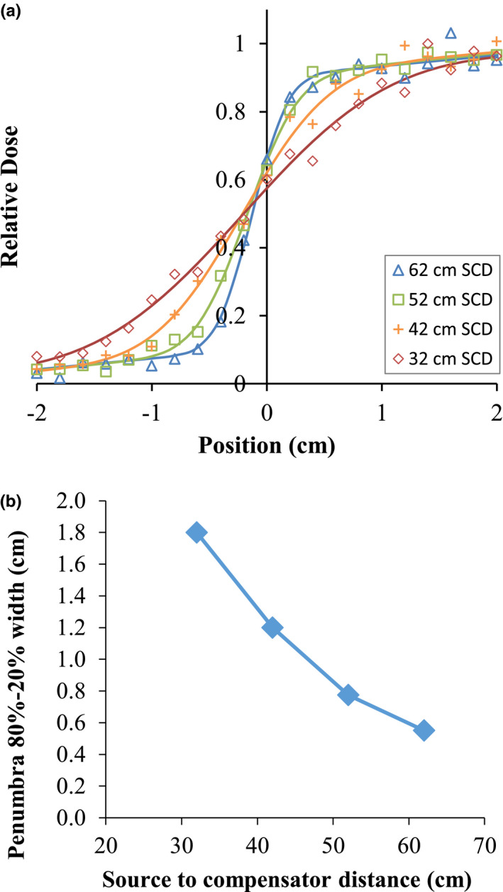
Profiles and 80–20% penumbra widths for a 60Co reference beam at various source‐to‐compensator distances, from Monte Carlo simulations. The penumbra model is an empirical fit with constant, linear, and sigmoidal components. [Color figure can be viewed at wileyonlinelibrary.com]
While the widths exceed 1 cm for the compensators placed farthest from the patient, compensators placed close to the patient produce penumbras comparable to 6 MV linacs with MLCs.18 A geometric limitation is the “bore size” dictated by the source to compensator distance (SCD), that is, the distance from the source to the proximal surface of the compensator. A 50 cm SCD leaves the bore at approximately 52 cm diameter for an 80 cm SAD machine or approximately 92 cm for a 100 cm SAD machine assuming compensators that are 2 TVL thick. This should accommodate most patients.
2.B.2. Surface dose
One concern about compensator‐based treatment is the potential increase in skin dose due to scattered photons and secondary electrons. To study the effect for this system, the 35 × 35 cm 60Co beam was projected through a uniform 1 TVL tungsten plate onto water at 70 cm SSD. In a series of simulations, the proximal surface of the plate was placed 10, 20, 30, and 40 cm above the water surface, and an additional run was made without the plate for comparison.
With no compensator plate, the surface dose averaged over the top 2 mm was 76% of the dose at a depth of maximum. With compensators, the doses were 60%, 66%, 74%, and 90% for SCDs of 40, 50, 60, and 70 cm, respectively (i.e., 40, 30, 20, and 10 cm from the patient surface). The last geometry (10 cm from patient surface) is not likely to be used in this device. The lack of increase relative to open beam is attributed to source and collimator scatter which reach the surface in the open beam but are blocked in the compensated beam, partially offsetting the additional scatter and secondary electrons when the compensator is in place. Some surface dose enhancement has previously been found in megavoltage linac beams, also decreasing as the compensator is moved away from the patient.19, 20 Because the skin dose is not increased except for the closest geometry, multi‐beam treatments should not cause an unusual degree of skin toxicity.
2.C. Treatment planning study
To assess the potential quality of radiotherapy delivery with this system, we performed IMRT treatment planning studies using 60Co beams as a worst‐case scenario for dosimetry quality. We benchmark 60Co compensator‐based plans against clinical MLC‐linac plans. This section describes the three components of this study: commissioning of a hypothetical machine in the Pinnacle treatment planning system (TPS), (Koninklijke Philips N.V., Eindhoven, Netherlands), the planning and plan comparison, and validation of the IMRT dosimetric accuracy through Monte Carlo simulations.
2.C.1. TPS commissioning
Pinnacle 9.8 was selected as the TPS for this work because it is already in use in the investigators’ clinic and has the features necessary for compensator‐based planning. Pinnacle has two limitations which particularly impacted this study: the simplicity of the compensator physics modeling and an apparent inability to accurately perform inverse planning at SADs other than 100 cm. We opted to proceed at 100 cm SAD because it was thought to qualitatively reflect the types of plans possible.
Pinnacle generates penumbras in the patient using a blurring function based on the collimator properties alone regardless of the presence of a compensator or its placement.* Thus, the critically important penumbra effects described in Section 2.B.1 are not modeled accurately when a machine is naively created with realistic physical parameters; the penumbra is far too large. We therefore commissioned an empirically tuned machine model for each compensator position.
We used data from EGSnrc simulations of fields projected through compensators with square openings as commissioning reference data in lieu of physical measurements on a machine. An example is shown in Fig. 3. The Pinnacle model simulates the beam profile well except in the out‐of‐field region where the predicted dose is low. As the validation results in Section 3.B show, the modulation accuracy is sufficiently accurate. The beam energy spectrum was reproduced from the literature21 and produces an acceptable PDD curve match.
Figure 3.
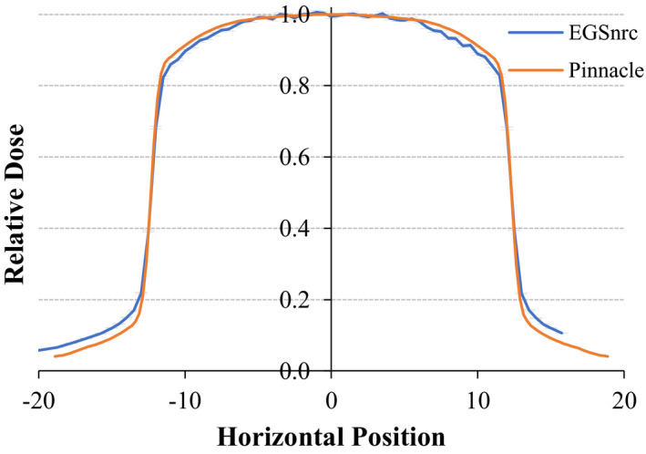
Comparison of a beam profile from the EGSnrc Monte Carlo model (blue with error bars) vs extracted profile from the machine modelled in Pinnacle (orange). [Color figure can be viewed at wileyonlinelibrary.com]
An additional modeling limitation is that Pinnacle treats the compensators as if they were perfectly thin attenuating layers rather than modeling them in three dimensions and tracing projections of rays through true physical distances. Practical consequences are discussed in Sections 3.B and 4.
2.C.2. Study description
Five clinical head‐and‐neck cases and five clinical gynecological cases were used in this study. Each has a nine‐field 6MV IMRT plan previously delivered clinically to the patients using an Elekta linac and these plans are used as the baseline for this study. The 60Co‐compensator system was used to re‐plan each case. The objectives from each clinical plan were used as a starting point to reduce planner bias, then were modified as needed to produce high‐quality 60Co‐compensator plans according to the behavior of that system. The opening density matrices (ODMs) were converted to compensators with a density of 19.3 g/cm3 (tungsten density) using the compensator functions in Pinnacle. The compensator parameters used were an SCD of 63 cm (as an example positioning close to the patient), a resolution of 2 mm (the native Pinnacle resolution), a maximum allowable compensator thickness of 4.8 cm (2 TVL) (equivalent to standard MLC attenuation), and nine beams (as used in the clinical plans) unless otherwise varied as described below.
The primary endpoints for the treatment planning study were PTV D 99% and D 2%, spinal cord D max and parotid D mean in the head‐and‐neck plans, and bladder D 35% and rectum D 60% for the gynecological plans as used in cooperative group trials (e.g., RTOG‐0418). All plans were normalized such that the mean PTV dose was equal to that of the clinical plan for each patient. We calculated the total treatment time for each plan, which is a special concern given the lower dose rates for 60Co machines. For clinical plans, we measured the actual treatment delivery time with a stopwatch for a sample plan (6 MV step‐and‐shoot IMRT) delivered on an Elekta linear accelerator with an Agility MLC head. We applied the resulting scaling factor (i.e., time per MU) to calculate total treatment times for the other plans. For 60Co plans we assumed a dose rate of 200 cGy/min under reference conditions (100 cm SAD, 0.5 cm depth, 10 × 10 cm2 field), a rate which is typical of new sources at 100 cm SAD. For all plans we assumed one extra minute for gantry rotation.
The effect on plan quality of changing different compensator characteristics was evaluated by varying one parameter at a time and then generating new 60Co‐compensator IMRT plans for all five head‐and‐neck cases. The following parameters were varied: SCD of 63 cm and 53 cm; compensator resolutions of 2, 4, 6, 8, and 10 mm via post‐optimization binning; maximum compensator thicknesses from 0.5 to 3 TVL; and the number of beams of 5, 7, 9, 11, and 13.
2.C.3. Dosimetric validation
To validate dose, calculations were performed in a water phantom from plan compensator beams in both Pinnacle and with EGSnrc and these dose distributions were compared in a virtual IMRT QA. For the EGSnrc calculations, the compensator matrix from each Pinnacle beam was converted into a focused 3D tungsten model within a DOSXYZnrc phantom file also containing a water volume. The 60Co beam was simulated for 2 × 10⁹ histories through each compensator to produce a dose distribution in water. The dose was evaluated in a plane centered at 5 cm depth in water voxels spanning 0.4 × 0.4 × 1.0 cm3 to balance the needs for high lateral resolution and low statistical variation. This provides a statistical standard deviation of approximately 1% in high‐dose areas. In Pinnacle, the compensator IMRT beams were copied to a QA phantom and a dose plane extracted at 5 cm depth at the level of isocenter. Code was written to perform gamma analysis22, 23 using the Monte Carlo data as the reference set and the Pinnacle data as the evaluated set. The relative dose scaling between the two data sets was manually optimized because the Monte Carlo data have statistical fluctuations which preclude simply using any one standard point dose. Pinnacle had previously been shown to accurately model cubic‐block‐piled tungsten‐PMMA compensators in 4 and 10 MV photons beams.24
3. Results
3.A. Plan quality
3.A.1. Comparison of plan quality: 6 MV‐MLC vs 60Co‐compensator
Example treatment plans for 6 MV‐MLC and 60Co‐compensator plans are shown in Figs. 4(a) and 4(b). Fig. 5 shows the corresponding DVHs for these two patients.
Figure 4.
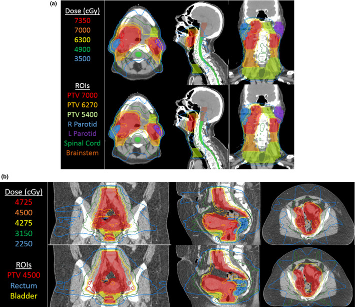
(a) Isodose lines from IMRT treatment plans for 6 MV‐MLC (top row) and 60Co‐compensator plans (bottom row) for one head‐and‐neck case selected as high‐quality plans. Parameters are the standard set listed in Section 2.C.2. (b) Isodose lines from IMRT treatment plans for 6 MV‐MLC (top row) and 60Co‐compensator plans (bottom row) for one gynecological case selected to show a good outcome. Parameters are the standard set listed in Section 2.C.2. [Color figure can be viewed at wileyonlinelibrary.com]
Figure 5.
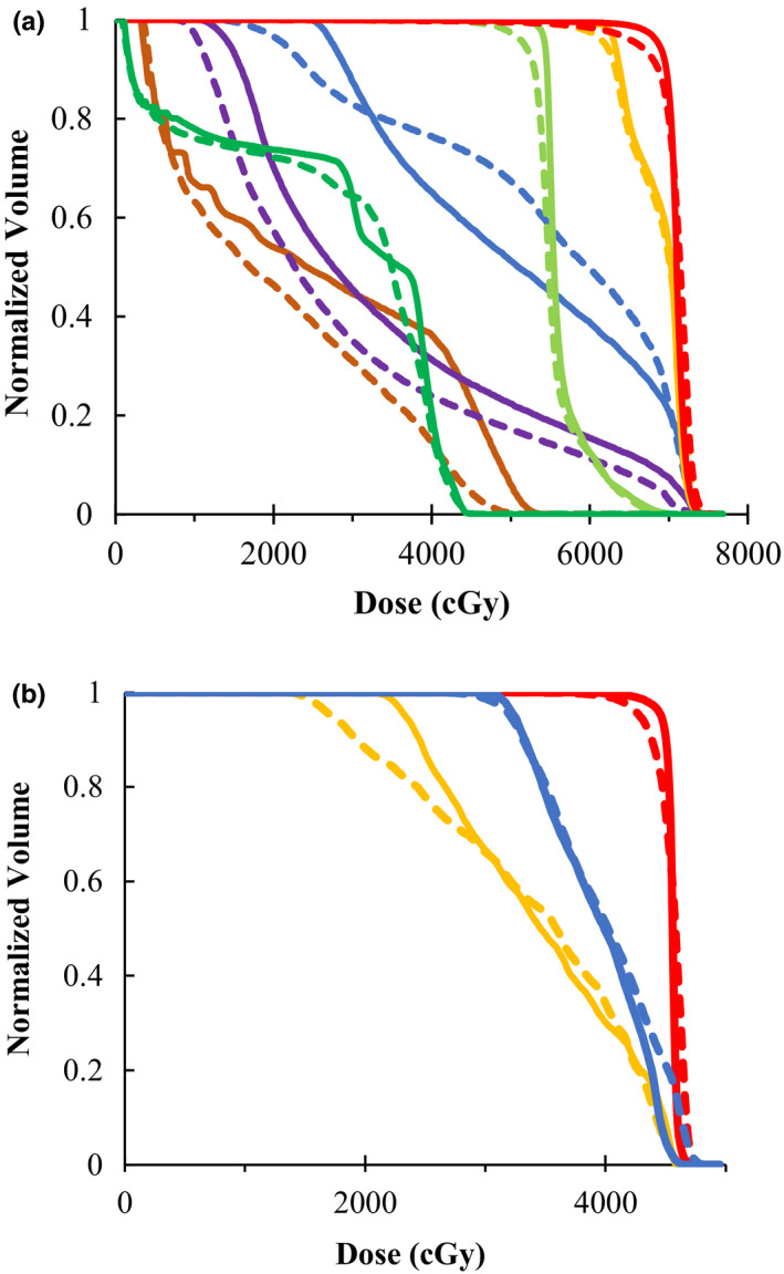
DVHs for the head‐and‐neck plan (left) and gynecological plan (right) in Fig. 4, with relevant ROIs. Solid lines refer to the 60Co‐compensator plans, and dashed lines refer to the 6MV‐MLC plans. Colors for the head‐and‐neck plan (left) are: PTV7000 (red), PTV6270 (orange), PTV5400 (light green), R parotid (blue), L parotid (purple), cord (green), brainstem (brown). Colors for the gynecological plan (right) are: PTV (red), rectum (blue), bladder (orange). [Color figure can be viewed at wileyonlinelibrary.com]
Table 1 shows the dosimetric endpoints for tumor coverage and organ‐at‐risk (OAR) dose in the 60Co‐compensator plans compared to the 6 MV‐MLC plans. The PTV coverage and hotspots were equivalent for the two techniques. The 60Co‐compensator plans had higher mean parotid dose (for head and neck cancer patients) and higher rectum D 60% (for gynecological cancer patients). While the individual OAR dose differences are not statistically significant between the 60Co‐compensator and 6 MV‐MLC plans, the trend is consistently toward higher OAR doses in the 60Co‐compensator plans. Discussion of the strong 60Co performance is in Section 4.
Table 1.
Plan quality metrics comparing 60Co‐compensators plans to baseline clinical 6 MV‐MLC plans. Five head‐and‐neck plans (top panel) and five gynecological plans (bottom panel) were generated for a 6 MV‐MLC, a 60Co‐compensator device with a 63‐cm SCD, and a 60Co compensator device with 53‐cm SCD. All compensator plans used 2 mm compensator resolution, 2 TVL maximum thickness, and 9 beams. Values shown indicate the percent deviation of the 60Co‐compensator plans from the 6 MV‐MLC plan ± one standard deviation
| Difference from 6 MV‐linac plan | ||
|---|---|---|
| 63 cm SCD | 53 cm SCD | |
| Head and neck endpoint | ||
| PTV D2% | +0.5 ± 1.7% | +1.5 ± 1.5% |
| PTV D99% | +2.0 ± 5.4 | −0.7 ± 6.3 |
| L parotid mean dose | +8.6 ± 8.9 | +14.0 ± 9.2 |
| R parotid mean dose | +7.4 ± 12.2 | +11.1 ± 15.1 |
| Cord max dose | +0.9 ± 6.9 | +0.9 ± 5.6 |
| Gynecological endpoint | ||
| PTV D2% | −0.8 ± 0.7% | −0.4 ± 0.8% |
| PTV D99% | +2.1 ± 3.0 | −0.9 ± 0.9 |
| Rectum D60% | +7.0 ± 13.1 | +7.1 ± 12.4 |
| Bladder D35% | +0.2 ± 1.2 | +0.2 ± 2.0 |
The calculated treatment times for head‐and‐neck plans were 7.6 ± 2.0 (mean ± 1 SD.) min for 6MV‐MLC vs 3.9 ± 0.9 min for 60Co‐compensator. For gynecological plans, treatment times were 8.7 ± 3.1 min vs 4.3 ± 0.4 min for 60Co‐compensator. The 60Co‐compensator plan is faster by a factor of 2.0 ± 0.6 (P < 0.001). One of the main reasons for the faster delivery is the fact that MLC‐linac plans require time for MLC leaf movement and also time for the beam to turn on. Our timing measurements indicate that this reduces the effective delivered dose rate by approximately a factor of 5, that is, the average effective dose rate is 107 MU/min from the MLC‐linac plan instead of the 600 MU/min as planned. An older source would have a slower delivery, but 80 cm SAD machines may deliver treatments even more quickly.
3.A.2. Effect of source‐to‐compensator distance
Table 1 shows results for both 63‐ and 53‐cm SCD plans. There was no clinically or statistically significant difference in dosimetry endpoints between these two setups.
3.A.3. Effect of compensator resolution
The effect on 60Co plan quality of reducing the compensator resolution via binning is displayed in Fig. 6. For the PTV D 2% and D 99%, the parotid mean dose, and the spinal cord D 1%, the change is <5% when the compensator resolution is changed from 2 to 4 mm. While there is no clear trend in the data for OAR doses, the PTV coverage was inferior at compensator resolutions of 6–10 mm, with >5% lower D 99% compared to plans with 2 mm compensator resolution. In addition, due to the fact that D 2% tends to grow as compensator resolution worsens (and D 99% tends to decrease), the data suggest that the dose distribution in the PTV is more homogeneous for finer resolutions.
Figure 6.
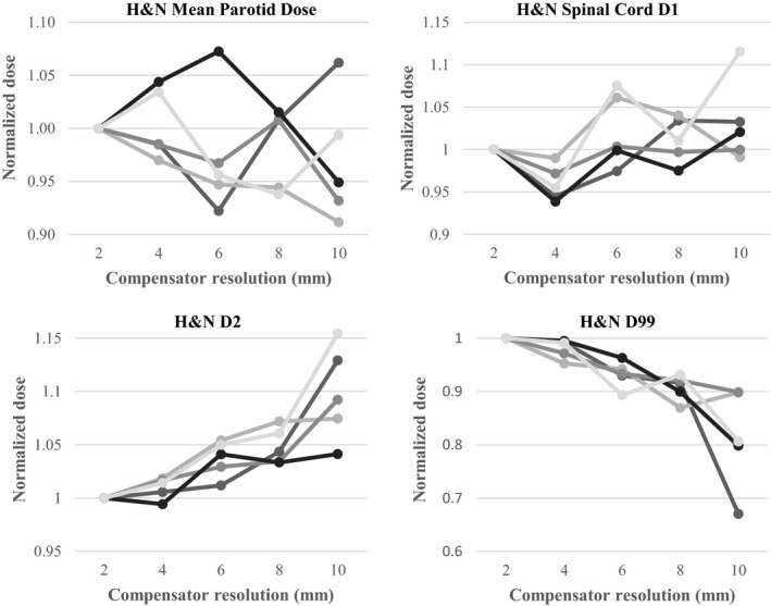
PTV and OAR doses for each of the five head and neck plan as a function of compensator resolution. Mean parotid dose and spinal cord D 1% (top: left to right). PTV D 2% and D 99% (bottom, left to right). Each line is data from a different patient plan. All doses are normalized to the 2 mm‐resolution compensator. All plans use 63 cm SCD, 2 TVL max thickness, and 9 beams.
3.A.4. Effect of maximum compensator thickness
Here, we assess the effect on plan quality of the maximum compensator thickness (i.e., the thickness beyond which Pinnacle truncates the optimized attenuation). Two cases had their compensator thickness varied between 0.5 and 3.0 TVL. Results for both are shown in Fig. 7. The OAR doses tended to drop for thicker compensators as they were better able to attenuate. In the gynecological case the PTV dose homogeneity also improved with thickness. There is negligible advantage to using greater than 2 TVL (4.8 cm tungsten in this study), and 1.5 TVL may be acceptable.
Figure 7.
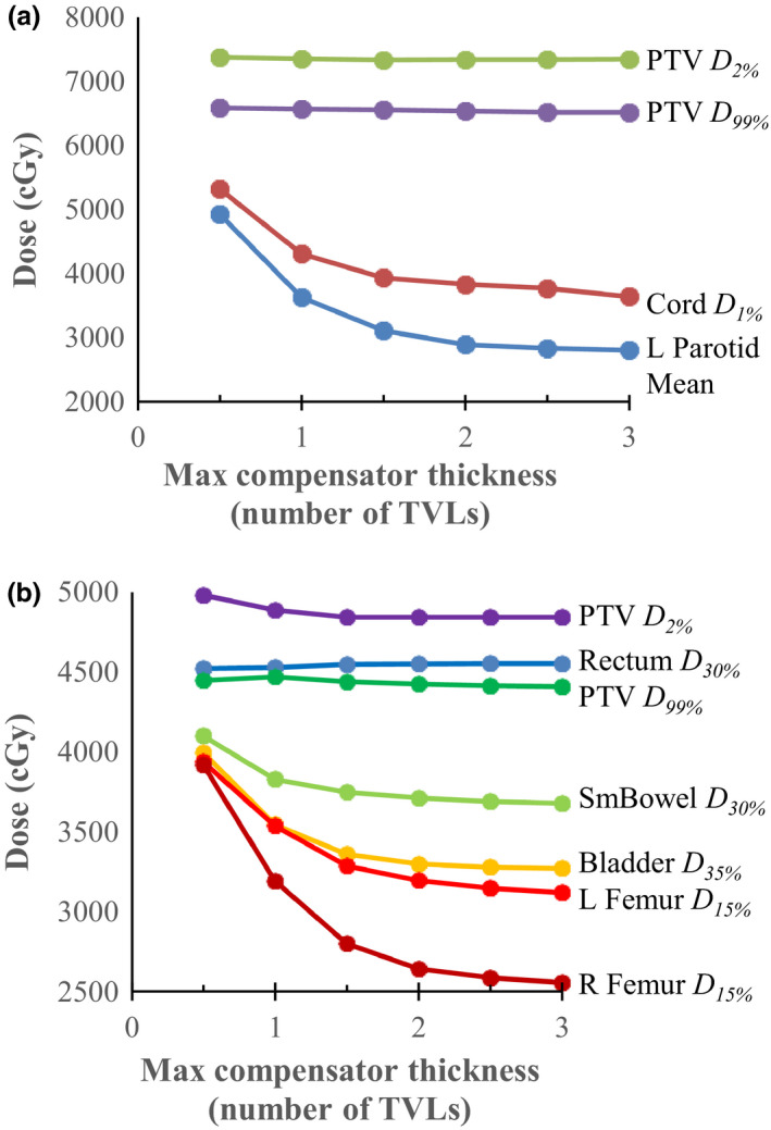
Dosimetric endpoints for a head‐and‐neck plan (top) and a gynecological plan (bottom) as a function of the maximum allowed compensator thickness (quoted in number of tenth‐value layers). For both cases the PTV D 2% and D 99% did not change as a function of maximum compensator thickness; however, the OAR doses decrease as the thickness increases. [Color figure can be viewed at wileyonlinelibrary.com]
3.A.5. Effect of the number of beams
No clear trends were observed with respect to tumor and OAR dose from varying the number of beams from 5 to 13. There were erratic changes of less than 2% in both PTV D 99% and PTV D 2% and less than 5% and 8% change in parotid mean dose and cord D 1 , respectively. Based on the study of Stein et al.,25 using either 7 or 9 beams would be appropriate in most cases.
3.A.6. Compensator mass
The plans generated above can be used to estimate the total volume (and mass) of compensators that would be required. For the standard parameters (63 cm SCD, 2 mm resolution, 2 TVL maximum thickness, and 9 beams), we found that the average field sizes in the head‐and‐neck and gynecological plans were 14.4 × 17.5 cm2 and 17.6 × 24.0 cm2, respectively. The fraction of the possible compensator volume within the field taken up by attenuator material was 0.54 ± 0.07 for head‐and‐neck plans and 0.49 ± 0.07 for gynecological plans at 4.8 cm maximum thickness.
A full‐thickness border may be necessary to allow for any misalignment between the compensator and jaws. The necessary size will depend on the final design details, so an approximate value of 1 cm is used here. The average compensator mass including border was 11.0 ± 3.6 kg for head‐and‐neck patients, and 14.9 ± 2.6 kg for gynecological patients assuming 63 cm SCD and density of tungsten. The mass will increase with distance from the source and with field size as the compensator must encompass the field projected at that distance. The physical width increases linearly with field size and SCD, so the in‐field mass increases quadratically and the border mass linearly. Tungsten compensators for 6MV beams would be approximately 25% thicker and heavier for the same attenuation. For large SCDs, it may not be possible to accommodate all the compensator plates in a ring if many beams are used. For the plans considered here, the limit is approximately 65 cm SCD if nine fields are used.
3.B. Dosimetric validation
Two head‐and‐neck and two gynecological plans were validated for the nominal 63 cm SCD machine. All nine IMRT beams from each plan were analyzed for a total of 36 beams. A compensator resolution of 2 mm was used. An example result is shown in Fig. 8. Beams have a median gamma pass rate 97.6% and minimum of 92.8% with 3% and 3 mm gamma criteria and a threshold of 10%. Differences are seen when comparing the least and most attenuated areas, an error which is a few percent and attributed to the low out‐of‐field dose in the Pinnacle model. Future modeling efforts in a different TPS may be able to reduce this error. We note that in performing this analysis, we assumed a 3D focused compensator to most closely match the simplified model for compensators that is used in Pinnacle (i.e., an infinitely thin compensator).
Figure 8.
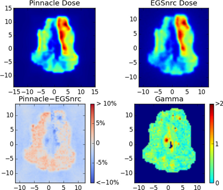
Example Monte Carlo validation of one compensator IMRT field for a head‐and‐neck case. Top: the dose planes in water extracted from Pinnacle and from the EGSnrc validation simulation. Bottom: the difference in dose as a percentage of maximum dose (left) and a map of gamma values (right) with criteria 3% and 3 mm, with a 10% threshold. In this case the pass rate was 97%. [Color figure can be viewed at wileyonlinelibrary.com]
There can be sharp gradients in the fluence generated in inverse planning in Pinnacle and correspondingly sharp features in the compensators. It is not possible to restrict the complexity of the compensators in Pinnacle during planning, so it must be noted that some such compensators may be challenging to manufacture. However, as the plan quality is fairly insensitive to feature size as shown in Section 3.A.3, more easily manufactured compensators can clearly suffice and should be even more accurately modeled in a TPS.
4. Discussion
The data presented here demonstrate that the proposed IMRT compensator system is capable of producing plans of comparable quality to 6 MV‐MLC systems. This is true even when 60Co beams are used, which may make the compensator system well‐suited to large portions of LMICs where 60Co units are the only available technology. While OAR sparing is decreased in some plans, the overall plan quality is well within the limits of clinically acceptable dose distributions. The delivery time for 60Co‐compensator plans was indeed shorter in our study than that of 6 MV‐MLC plans by an average factor of 2.0 ± 0.6 (i.e., average total delivery time of 4.1 ± 0.7 min vs 8.2 ± 2.6 min).
Currently MLCs are the most widely used technology to deliver IMRT. The alternative method of physical compensators has a long history.26 Advantages of using compensators over MLC include: simplicity, lower cost, and less repair. It may also be easier to develop a quality assurance (QA) procedure for a static device vs a moving MLC.27
While compensators have a long history there are several innovative design features here. First, the compensator system could employ reusable attenuation material to modulate the radiation beams. We proposed a system which uses compensator shells made from plastic which is lightweight and easily manufactured. Previous authors have proposed the method of using milled negative molds,14, 28 for example, the system described by Chang et al.26 in which the compensator is milled into a Styrofoam mold which is then packed with reusable tin or tungsten particles. Another approach is piled cubic blocks which also allows for reusable compensators.24, 29 Some authors have even proposed using liquid metal (e.g., mercury)30 or describe a reshapable automatic intensity modulator, in which an attenuator made of tungsten powder, silicon binder and paraffin is shaped by an array of steel pistons.31, 32 Any of these methods obviate one of the historic disadvantages of compensators which is the need for on‐site milling of large metallic objects (typically brass) or a mail‐order system, neither of which is practical in the LMIC environment. Our study shows that the dosimetric properties of our proposed system with reusable attenuation were excellent.
A second feature of the compensator system design proposed here is to mount the compensators on a ring or other arrangement to avoid the time required in changing blocks between each field delivery. Block changes are known to greatly increase the overall treatment time.11 Therefore, a design which eliminates the need for manual changes of blocks will greatly increases efficiency A similar concept was proposed by Yoda and Aoki14 in 2003, which used a rotating multi‐port “pizza pan” mounted on the head of the linear accelerator, though to our knowledge this was never commercialized beyond a test system with the Mitsubishi linear accelerator. The rotation of the port assembly could be controlled from outside the vault to bring the appropriate compensator into place. Similarly O'Daniel et al.33 consider a single compensator with multiple regions that could rotate with the collimator.
The planning exercise conducted here used 60Co beams, which were taken as a “worst‐case scenario” due to the lower energy, large source size and a decaying dose rate.34 While it may seem surprising that treatments with high gradients are possible with 60Co beams, this can be explained by IMRT's ability to partially compensate unfavorable penumbras through beam modulation. This is well‐known and explored in many previous studies, for example, Joshi et al.35 The use of multiple beams also partially compensates for the unfavorable depth dose of 60Co. The study by Fox et al. shows that the differences between treatments of 60Co IMRT and high energy linacs were negligible if 9 or more beams were used.36 The results presented here on plan quality are consistent with numerous other studies which examined 60Co IMRT37, 38, 39, 40, 41 and showed it to be comparable in quality to MV photon teletherapy. Some of these studies were conducted and motivated by the fact that 60Co was used in the first‐generation devices from ViewRay Inc (Oakwood, OH, USA).42
In our study, the delivery of 60Co‐compensator treatments required approximately half the time of 6MV‐MLC plans. This may be surprising because treatments with 60Co teletherapy units are often thought to be longer due to the lower dose rates. There are, however, are several other factors which drive longer treatment times when IMRT is delivered with an MLC‐linac combination. These include MLC leaf motion time and beam‐on initiation time. MLC‐IMRT also utilizes small fields where most of the output is blocked. All these factors reduce the effective delivered dose rate. Our measurements indicate an average reduction by a factor of 5 in the delivered dose rate vs the planned dose rate for MLC‐IMRT. By comparison compensators use dose very efficiently which is a well‐known effect and accounts for the shorter treatment times.26 We note, however, that the difference in delivery times may be less marked if one considers VMAT deliveries instead of IMRT. Most studies of VMAT find that it uses fewer monitor units and has shorter treatment times than IMRT,43 although the magnitude of these differences is highly variable. An uncertainty is the additional time may be required to mount the compensators at the beginning of the treatment. While a full consideration of this is beyond the scope of this paper because the system is in development, the effect may be minimized with automatic loading systems and/or workflow solutions.
If 60Co can be employed in the system proposed here, it may provide many advantages, including lower cost, simplicity, less complex quality assurance procedures, and reduced maintenance and downtime. There are particularly profound advantages to 60Co units in those regions that have unstable power rids, fluctuating power outages, and blackouts as reported by a recent modeling study.11 However, it is important to note that the compensator‐ring system described here is not restricted to 60Co beams and can also work with a linac. It would provide the same advantages of mechanical simplicity, less complex quality assurance procedures, reduced maintenance and downtime, and shorter treatment times.
In considering the development of the compensator‐ring system proposed here it is important to understand the effects of the various design parameters. We found that plan quality is fairly insensitive to most of the parameters of the compensator system. The largest effect appeared to be the maximum allowed thickness of the compensator. With an allowed 2 TVL, OAR sparing is similar to 6 MV‐MLC plans, but degrades substantially when the thickness is allowed to be less than 1.5–2 TVL. The compensator resolution does not appear to have a major effect until it becomes coarser than approximately 6 mm. The source‐to‐compensator distance also does not appear to have a substantial impact on plan quality and an SCD of even 53 cm should be achievable (i.e., 47‐cm clearance isocenter‐to‐patient on a 100 SAD machine). For comparison, we note that the lower collimator of the T780 device is at 27.6 cm from the source which on an 80 cm SAD machine provide an effective clearance of 52.4 cm. One of the potential disadvantages of a compensator system is increased skin dose, but Monte Carlo simulations presented here suggest that this also is not a consequential effect.
There are some limitations of this study. The treatment planning system used here, while capable of including compensators, has a simplified model for the compensators which does not fully capture or optimize the 3D geometry of the compensator or secondary effects such as beam hardening in the case of a linac spectrum and also scatter in the components. The TPS was also only able to model a 100 SAD system, so it is unclear how the details of the findings here would translate into an 80 SAD system as is often used in 60Co teletherapy units. The relative insensitivity of plan quality to SCD, however, suggests that a change in SAD may not have a large effect.
Future work includes the development of a prototype system, work which is underway with industry collaboration. There are numerous practical issues to address, including the process for producing compensator molds, the process for filling/unfilling and the time required, the quality assurance process for the devices, and systems to ensure that correct compensator(s) are used for the correct patient. QA processes may include loaded compensator weight and surface geometry verification. Absolute dosimetry and the effect from the plastic mold layer in these compensated beams will need to be addressed when design is finalized. Also required is a TPS solution that is viable for the LMIC environment and is validated for use with compensators. Some form of image guidance would need to be integrated into treatment, such as kV or MV images taken without compensators mounted, or fitted within the compensator ring. This will have to be accounted for in the final design of the system.
5. Conclusions
A novel design for a compensator‐based IMRT system is proposed. The planning studies presented here suggest that it is capable of delivering plans which are similar in quality to standard linac‐based MLC technologies. While the system would work with linacs and could potentially be retrofitted onto existing systems, results indicate that even 60Co treatment beams our proposed system can deliver similar quality plans with treatment times of less than 5 min. There are many potential advantages of such a system in terms of cost and reliability and further development may improve access to IMRT in LMICs where the need of state‐of‐art RT for cancer patients is acute and growing.
Acknowledgments
This work was partially funding by NCI grant UG3 CA211310‐01. Use of patient data for this study was approved by an institutional review board. Author G.V.S. is an employee of Pancea Medical Technologies Pvt. Ltd.
Note
Philips product support, private communication.
Contributor Information
Jonathon Van Schelt, Email: jonathon_vanschelt@rush.edu.
Eric C. Ford, Email: eford@uw.edu.
References
- 1. Ferlay J, Soerjomataram I, Dikshit R, et al. Cancer incidence and mortality worldwide: sources, methods and major patterns in GLOBOCAN 2012. Int J Cancer. 2015;136:E359–E386. [DOI] [PubMed] [Google Scholar]
- 2. Bray F, Soerjomataram I. The changing global burden of cancer: transitions in human development and implications for cancer prevention and control. In: Gelband H, Jha P, Sankaranarayanan R, Horton S, eds. Disease Control Priorities: Cancer, 3rd ed. Washington: World Bank Publications; 2015: 24–44. [PubMed] [Google Scholar]
- 3. Sloan FA, Gelband H. The cancer burden in low‐and middle‐income countries and how it is measured; 2007. [PubMed]
- 4. Delaney G, Jacob S, Featherstone C, Barton M. The role of radiotherapy in cancer treatment. Cancer. 2005;104:1129–1137. [DOI] [PubMed] [Google Scholar]
- 5. Baskar R, Itahana K. Radiation therapy and cancer control in developing countries: can we save more lives? Int J Med Sci. 2017;14:13. [DOI] [PMC free article] [PubMed] [Google Scholar]
- 6. Jaffray DA, Knaul FM, Atun R, et al. Global task force on radiotherapy for cancer control. Lancet Oncol. 2015;16:1144–1146. [DOI] [PubMed] [Google Scholar]
- 7. Abdel‐Wahab M, Bourque JM, Pynda Y, et al. Status of radiotherapy resources in Africa: an International Atomic Energy Agency analysis. Lancet Oncol. Apr 2013;14:e168–e175. [DOI] [PubMed] [Google Scholar]
- 8. Kohler RE, Sheets NC, Wheeler SB, Nutting C, Hall E, Chera BS. Two‐year and lifetime cost‐effectiveness of intensity modulated radiation therapy versus 3‐dimensional conformal radiation therapy for head‐and‐neck cancer. Int J Radiat Oncol Biol Phys. 2013;87:683–689. [DOI] [PubMed] [Google Scholar]
- 9. Lin A, Kim HM, Terrell JE, Dawson LA, Ship JA, Eisbruch A. Quality of life after parotid‐sparing IMRT for head‐and‐neck cancer: a prospective longitudinal study. Int J Radiat Oncol Biol Phys. 2003;57:61–70. [DOI] [PubMed] [Google Scholar]
- 10. Mell LK, Mehrotra AK, Mundt AJ. Intensity‐modulated radiation therapy use in the US, 2004. Cancer. 2005;104:1296–1303. [DOI] [PubMed] [Google Scholar]
- 11. McCarroll R, Youssef B, Beadle B, et al. Model for estimating power and downtime effects on teletherapy units in low‐resource settings. J Global Oncol. Oct 2017;3:563–571. [DOI] [PMC free article] [PubMed] [Google Scholar]
- 12. Jiang SB, Ayyangar KM. On compensator design for photon beam intensity‐modulated conformal therapy. Med Phys. May 1998;25:668–675. [DOI] [PubMed] [Google Scholar]
- 13. Salz H, Wiezorek T, Scheithauer M, Schwedas M, Beck J, Wendt TG. IMRT with compensators for head‐and‐neck cancers treatment technique, dosimetric accuracy, and practical experiences. Strahlenther Onkol. 2005;181:665–672. [DOI] [PubMed] [Google Scholar]
- 14. Yoda K, Aoki Y. A multiportal compensator system for IMRT delivery. Med Phys. May 2003;30:880–886. [DOI] [PubMed] [Google Scholar]
- 15. Kawrakow I, Rogers D. The EGSnrc code system: Monte Carlo simulation of electron and photon transport; 2000.
- 16. Rogers D, Kawrakow I, Seuntjens J, Walters B, Mainegra‐Hing E. NRC user codes for EGSnrc. NRCC Report PIRS‐702 (Rev. B); 2003.
- 17. Dhanesar SK. The Role of Cobalt‐60 Source in Intensity Modulated Radiation Therapy: From Modeling Finite Sources to Treatment Planning and Conformal Dose Delivery. Kingston: Queen's University; 2013. [Google Scholar]
- 18. Thompson C, Weston S, Cosgrove V, Thwaites D. A dosimetric characterization of a novel linear accelerator collimator. Med Phys. 2014;41:031713. [DOI] [PubMed] [Google Scholar]
- 19. Jiang SB, Ayyangar KM. On compensator design for photon beam intensity‐modulated conformal therapy. Med Phys. 1998;25:668–675. [DOI] [PubMed] [Google Scholar]
- 20. Cardarelli GA, Rao S, Cail D. Investigation of the relative surface dose from Lipowitz‐metal tissue compensators for 24‐and 6‐MV photon beams. Med Phys. 1991;18:282–287. [DOI] [PubMed] [Google Scholar]
- 21. Sichani BT, Sohrabpour M. Monte Carlo dose calculations for radiotherapy machines: Theratron 780‐C teletherapy case study. Phys Med Biol. 2004;49:807. [DOI] [PubMed] [Google Scholar]
- 22. Hussein M, Clark C, Nisbet A. Challenges in calculation of the gamma index in radiotherapy–Towards good practice. Physica Med. 2017;36:1–11. [DOI] [PubMed] [Google Scholar]
- 23. Low DA, Harms WB, Mutic S, Purdy JA. A technique for the quantitative evaluation of dose distributions. Med Phys. 1998;25:656–661. [DOI] [PubMed] [Google Scholar]
- 24. Sasaki KOY. Dosimetric characteristics of a cubic‐block‐piled compensator for intensity‐modulated radiation therapy in the Pinnacle radiotherapy treatment planning system. J Appl Clin Med Phys. 2007;8:85–100. [DOI] [PMC free article] [PubMed] [Google Scholar]
- 25. Stein J, Mohan R, Wang XH, et al. Number and orientations of beams in intensity‐modulated radiation treatments. Med Phys. 1997;24:149–160. [DOI] [PubMed] [Google Scholar]
- 26. Chang SX, Cullip TJ, Deschesne KM, Miller EP, Rosenman JG. Compensators: an alternative IMRT delivery technique. J Appl Clin Med Phys. 2004;5:15–36. [DOI] [PMC free article] [PubMed] [Google Scholar]
- 27. Baka IA, Laub WU, Nusslin F. Compensators for IMRT–an investigation in quality assurance. Z Med Phys. 2001;11:15–22. [DOI] [PubMed] [Google Scholar]
- 28. Salz H, Wiezorek T, Scheithauer M, Kleen W, Schwedas M, Wendt TG. Intensity modulated radiotherapy (IMRT) with compensators. Z Med Phys. 2002;12:115–121. [DOI] [PubMed] [Google Scholar]
- 29. Nakagawa K, Fukuhara N, Kawakami H. A packed building‐block compensator TETRIS–RT and feasibilityfor IMRT delivery. Med Phys. 2005;32:2231–2235. [DOI] [PubMed] [Google Scholar]
- 30. Goodband J, Haas O, Mills J. Modelling mould attenuation for liquid metal compensators. Syst Sci. 2005;31:45–52. [Google Scholar]
- 31. Xu T, Al‐Ghazi MS, Molloi S. Treatment planning considerations of reshapeable automatic intensity modulator for intensity modulated radiation therapy. Med Phys. Aug 2004;31:2344–2355. [DOI] [PubMed] [Google Scholar]
- 32. Xu T, Shikhaliev PM, Al‐Ghazi M, Molloi S. Reshapable physical modulator for intensity modulated radiation therapy. Med Phys. Oct 2002;29:2222–2229. [DOI] [PubMed] [Google Scholar]
- 33. O'Daniel JC, Dong L, Kuban DA, et al. The delivery of IMRT with a single physical modulator for multiple fields: a feasibility study for paranasal sinus cancer. Int J Radiat Oncol Biol Phys. 2004;58:876–887. [DOI] [PubMed] [Google Scholar]
- 34. Van Dyk J, Battista JJ. Cobalt‐60: an old modality, a renewed challenge. Curr Oncol. 1996;3:8–17. [Google Scholar]
- 35. Joshi CP, Darko J, Vidyasagar P, Schreiner LJ. Investigation of an efficient source design for Cobalt‐60‐based tomotherapy using EGSnrc Monte Carlo simulations. Phys Med Biol. 2008;53:575. [DOI] [PubMed] [Google Scholar]
- 36. Fox C, Romeijn HE, Lynch B, Men C, Aleman DM, Dempsey JF. Comparative analysis of 60Co intensity‐modulated radiation therapy. Phys Med Biol. 2008;53:3175. [DOI] [PubMed] [Google Scholar]
- 37. Adams E, Warrington A. A comparison between cobalt and linear accelerator‐based treatment plans for conformal and intensity‐modulated radiotherapy. Br J Radiol. 2008;81:304–310. [DOI] [PubMed] [Google Scholar]
- 38. Schreiner LJ, Kerr A, Salomons G, Dyck C, Hajdok G. The potential for image guided radiation therapy with Cobalt‐60 tomotherapy. In: Ellis RE, Peters TM, eds. Medical Image Computing and Computer‐Assisted Intervention – MICCAI 2003: 6th International Conference, Montréal, Canada, November 15–18, 2003. Proceedings. Berlin, Heidelberg: Springer Berlin Heidelberg; 2003:449–456. [Google Scholar]
- 39. Dhanesar S, Darko J, Joshi CP, Kerr A, John Schreiner L. Cobalt‐60 tomotherapy: clinical treatment planning and phantom dose delivery studies. Med Phys. 2013;40:081710. [DOI] [PubMed] [Google Scholar]
- 40. Cadman P, Bzdusek K. Co‐60 tomotherapy: a treatment planning investigation. Med Phys. 2011;38:556–564. [DOI] [PubMed] [Google Scholar]
- 41. Joshi CP, Dhanesar S, Darko J, Kerr A, Vidyasagar P, Schreiner LJ. Practical and clinical considerations in Cobalt‐60 tomotherapy. J Med Phys. 2009;34:137. [DOI] [PMC free article] [PubMed] [Google Scholar]
- 42. Saenz DL, Paliwal BR, Bayouth JE. A dose homogeneity and conformity evaluation between ViewRay and pinnacle‐based linear accelerator IMRT treatment plans. J Med Phys. 2014;39:64. [DOI] [PMC free article] [PubMed] [Google Scholar]
- 43. Ren W, Sun C, Lu N, et al. Dosimetric comparison of intensity‐modulated radiotherapy and volumetric‐modulated arc radiotherapy in patients with prostate cancer: a meta‐analysis. J Appl Clin Med Phys. 2016;17:254–262. [DOI] [PMC free article] [PubMed] [Google Scholar]


