

Abstract
Wearable eye tracking devices have broad uses in medicine, psychology, augmented & virtual reality and consumer market research. Most mobile eye trackers available today utilize infrared imaging of the pupil and corneal reflections with video cameras. This tracking method requires sophisticated real-time processing of video signals consuming substantial electrical power. This method is thus unsuitable for light weight wearables such as adaptive smart eyeglasses for correction of presbyopia. In this paper we present a low-profile, low-power (7.7 mJ/sample) digital eye tracker oculometer based on infrared sclera tracking. The system is implemented using eight, 24-bit infrared proximity sensors and synchronous infrared LEDs. The pupil location is determined from 32 reflected pulsed light measurements independent of ambient illumination. The digital oculometer is 3.1 mm thick and weighs ~3 g. The tracker mounts adjacent to the tunable lenses in the smart eyeglasses frame. The eye tracker showed a pointing error of 1.3 degrees rms over a vertical and horizontal range of 30 degrees when tested by an observer.
Keywords: Mobile devices, older adults, health sensors, eye tracking
I. Introduction
An extensive array of different eye tracking devices and methods have been developed over the past four decades [1-3] with varying degrees of portability and suitability for different (lab, mobile) environments and accuracy requirements. The majority of today’s devices are based on the analysis of video images. Video-based eye-tracking systems are available as head-mounted technologies (e.g., Dikablis Mobile eye-tracker, Pupil Labs eye-tracker, SMI Glasses, and Tobii Glasses). These mobile systems can operate for long times and are minimally intrusive from the user’s perspective; hence they have enabled the study of visual perception and eye behavior outside of laboratory environments. In this paper we discuss the implementation of a very slim and low-power eye tracker suitable for lightweight smart eyeglasses applications.
II. Eye Tracking for Smart Eyeglasses
Unlike conventional corrective eyeglasses, smart eyeglasses [4,5] utilize tunable-power eyepieces that can provide external vision accommodation when the internal eye accommodation is lost or degraded. These devices can thus correct refractive vision errors and restore much of normal vision when accommodation is lost for example by age-related presbyopia, a condition affecting more than one billion people worldwide [6]. The eyepiece power is function of the user’s reduced accommodation behavior, the prescription vector and the distance from the user to the object observed as shown in Fig. 1. Gaze detection and passive stereo triangulation by eye tracking thus provides a natural way of measuring this distance without any additional active ranging hardware.
Figure 1:

Smart eyeglasses restore lost accommodation by utilization of variable power eyepieces. The required eyepiece power is a function of the object distance. This distance can be measured passively using eye trackers and stereo triangulation.
The applicability of current mobile eye tracking methods to smart eyeglasses poses two significant challenges. First, while most mobile trackers are minimally intrusive from the user’s perspective; they are highly noticeable and do not look natural to those around the user. This can greatly affect the social interactions of the user with others around him. It is thus highly desirable that the tracker be very slim and hidden from the view of others.
The second challenge is the electrical power consumption. Most mobile eye trackers available today are highly accurate and utilize real-time computation-intensive processing of high-resolution video signals with corresponding power-hungry microprocessors. These systems in general require backpack batteries or plugged-in connectivity. They are thus unsuitable for light and very low power mobile eyeglass applications. Recently Adhawk Microsystems developed an eye tracker that is both small and low-power based on a miniature MEMS micromirror scanner [15] and one or more infrared receivers. This approach results in a very small form factor. An issue that still remains unaddressed is the susceptibility of high-speed, low-power micromirrors to shock [16,17] and the tradeoff between shock resistance and bandwidth [18-19]. In the smart eyeglass application the eyetracker has to survive an impact of several 1000 G’s when eyeglasses are dropped on a hard floor from a typical height of 2m. For this reason in this paper we selected an eye tracking approach that resembles the operation of a MEMS scanner but without any moving components. The eyetracker does so by projecting light on the eyeball from multiple sources from a few directions while receiving the reflected light at a few discrete sensor locations.
III. Eye Tracking with Infrared Oculography
Both challenges can be addressed if the eye tracking is not based on processing of information-rich video images and video recording systems but instead on a reduced, less-accurate, set of eye position sensors. For example, infrared oculometers [7-12] (IROC’s) are much simpler devices that measure the light reflected from the human eye at different locations under different infrared illumination directions. IROCs require minimal computation which directly translates into low energy consumption per sample. The major drawback of IROCs compared to video-processing methods is its relatively lower accuracy due to the inevitable reduced sensor nonlinearities and human eye variations that can be captured and compensated with a reduced set of sensor measurements. Nevertheless, these devices can be utilized if the required pointing accuracy is adequate for the application at hand. An additional advantage of IROCs used for distance ranging is that detected signals are generally independent of external illumination levels. Hence, IROCs can work even in completely dark environments.
The gaze angle accuracy for stereo distance ranging required for lens adjustment is not very high. Most humans cannot distinguish errors in the lens power smaller than ∣ΔP∣~0.5D. In the worst case of no remnant eye accommodation, all lens power adjustments required by a shift in the object distance are realized by the tunable power eyepieces. The eyepiece error thus translates to an equivalent gaze angular resolution of
| (1) |
where Lip is the eye interpupillary distance, about 62 mm for most people. From these values an eye tracker with Δθ ~ 1 degree resolution is hence adequate for adaptive eyeglasses applications. In the sections below we discuss the implementation of a low power digital oculometer eye tracker for this application.
IV. Low-Power Digital infrared Oculometer
Oculometers measure invisible infrared light reflected from the eye using an array of sensors and infrared illumination sources placed around the eye. Our oculometer is placed between the lens and the eye, in very close proximity, roughly 2-3 cm away from the pupil as shown in Fig. 2. The oculometer has an array of eight light sources (infrared LEDs) and eight highly sensitive digital infrared detectors distributed around the lens aperture and right above the lens actuators. This distribution of sensors and light sources does not block the lens aperture and it is hidden from external observers. There are basically two types of operation modes for these devices.
Figure 2:

Oculometer and tunable eyepiece lens arrangement. The oculometer is placed adjacent to the eyepieces. The distance between the eye and the pupil is 2-3 cm.
Bright pupil tracking systems [12] rely on the emergence of a very bright pupil spot when the illumination and detector are nearly collinear within ~5 degrees of each. The pupil shows very bright under these conditions because the eye pupil and the retina behind it behave as a spherical retro-reflector [13]. No light is reflected if the incidence angle is larger than ~5 degrees as the reflected light cannot leave the eyeball interior. Bright pupil tracking systems are attractive because they require simple tracking of a single well defined bright source; hence the received signals are independent of the rest of the relatively dark eye and face background. Bright pupil systems work well at long distances from the eye, but they are very difficult to implement if they are placed in close proximity of the eye. For example, the separation distance must be larger than that necessary to span the eye motion under a limited illumination cone. This typically translates on a separation distance > 5 cm. Since the eye to oculometer distance for this application is smaller than this distance, a simple bright eye implementation cannot be easily realized.
Dark pupil trackers [12] do not require collinear illumination Typically, they do not track the pupil but brighter adjacent features such as the sclera (the white areas of the eye) or the limbus (the boundary between the sclera and the pupil) under broad angle illumination. Dark eye systems track the position of the pupil indirectly even at very close illumination distances. In fact, the closer they are, the smaller amount of illumination required and the lower the power dissipation is.
A. IR LED and Detector Arrangement
Fig. 3 shows the specific arrangement for our low-profile oculometer. Eight infrared LEDs and eight digital light sensors are evenly placed along a circle, 22.5 degrees from each other forming a regular octagram. The LEDs and detectors are labeled L0-L7 and D0-D7, respectively.
Fig. 3:

Arrangement of IR LED and digital light detectors in the oculometer. Note that there are 8 possible terms of LED-detector distance 1-4.
There is a total of 64 possible LED-detector measurement combination terms Li Dj. The strength of each Li Dj, is determined by the scattering of light from one IR LED to the corresponding detector chip. The amount of light received is a function of many parameters inclusive of the distances a and b between the light source to object and object to detector, the angle-dependent reflectivity of the object (eye) surface, the illumination, reflection and detection angles and the type of illumination source [14]. The reflected light intensity of each characteristic ray received by the detector is also inversely proportional to the square of object and source distances.
| (2) |
The total detector response is obtained by integration of the intensities received from all possible rays. This calculation does not yield closed form [14].
A simple empirical localization however can be obtained by addition and subtraction of LiDj terms. Through addition or subtraction of sums of these terms one can measure the amount of reflected light and reflection light differences between the left and right and top and bottom of the eye. The strength of these differences depends on the specific location of the dark pupil. Sums and differences of these terms can thus be utilized to produce two signals indicative of the dark pupil location coordinates with respect to a reference location. These empirical signals are input into a polynomial map to produce responses that are nearly linear with pupil location.
B. Pupil Localization Sums
Different combinations of sums and differences can be calculated to determine the location of the pupil. Near neighbor LED-detector sums measure the amount of incident and reflected light as sensed on the same half of the eye.
| (4) |
Where the (1) index indicates the distance between LED and detector which is one branch apart. The normalized quantities
| (5) |
are proportional to the pupil center coordinates. Higher order sums can be calculated between LEDs and detectors which are further apart. Thus,
| (6) |
| (7) |
| (8) |
with corresponding normalized location estimates
| (9) |
Each of these near and far estimates require exactly 8 different terms and an x-y localization requires reading of 32 LiDj terms. Different linear and nonlinear combinations of near and far location estimates can also be utilized to minimize mapping errors. In our implementation we utilize a polynomial map [12] to further linearize the oculometer response.
C. Digital Circuit Implementation
The oculometer circuit consists of eight LED-detector modules connected to a control bus. The tracker circuit utilizes eight synchronous 24-bit digital infrared proximity detectors (Si1153, Silicon Labs). An attractive feature of the Si1153 chip is that it is able to reject ambient illumination because the signal detected by this chip is modulated and narrowband. Fig. 4 shows a block diagram of one of the modules. Each 850 mil IR LED is driven by an asynchronous pulsed signal generated by a Si1153 detector from any of the eight modules. This is accomplished by multiplexing the Si1153s pulsed outputs onto a common shared bus line (LED pulse).
Fig. 4:
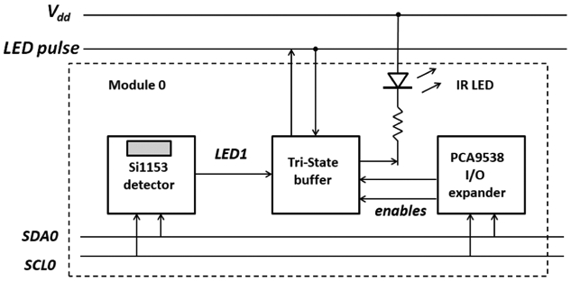
Schematic of digital oculometer circuit modular pulsing and detection module. The oculometer has eight of these modules.
The corresponding LED is connected to or disconnected from the bus using a tri-state CMOS switch chip (74LVC2G125). The bus line connection is controlled by a 4-bit register multiplexing control chip (PCA9538). All chips are controlled through an I2C digital bus. Furthermore, since the Si1153s and PCA9538 chips have unique I2C addresses, a 4-channel I2C expander chip (PCA9546) is utilized to generate four independent I2C buses, one for each module, to prevent address clashes. This circuit can be operated in several modes. In the simplest mode one can measure each LiDj term one at a time if only one LED-detector pair is activated. The circuit can also be driven in a ganged, octal parallel mode if a single LED is connected to a single driving Si1153, while seven other Si1153s receive the LED signals simultaneously. Octal mode operation increases the measurement speed and decreases power consumption.
Fig. 5 shows a photograph of the digital oculometer system assembled and surface mounted on a high-density 1 mm-thick four-level PCB. The standby power consumption of this system is < 6 μW. Each 850 nm infrared LED (VSMY1850X01) has an approximate Lambertian light emission characteristic. At an LED current of 64 mA, each LED produces a radial intensity of ~8 mW/sr when pulsed. Each LiDj term is measured by polling the system with a microcontroller.
Fig. 5:

Photograph of low-profile oculometer. The oculometer is only 3.1 mm thick and fits on top of the tunable eyepiece.
Each Si1153 detector is configured to record 24-bit infrared signals integrated over a specified number of pulses. We use a 32-pulse stream of 24 μs LED pulses per readout. This produces an LED electrical energy consumption of about 240 μJ for each LiDj term and 1.9 mJ for each the 8-term set. When one accounts for the energy required for the I2C communications and the computation of the sums and normalizations of (4)-(7) performed by an ATMega328P at 8 MHz, one obtains a total energy of about 7.7 mJ/pupil location measurement. Since the eye tracker operates in close proximity of the eye, significant additional energy savings can be realized by utilization of more efficient illumination schemes, such as the use of narrower beam angle IR LEDs.
V. Experiments
The oculometer was tested with two distinct automated setups and with a human observer. The automated setups are useful to determine the performance of the oculometer quantitatively while the human subject test determines the functionality of the eye tracker on a real eye. Fig. 6 shows photographs of the automated setups. The first setup measures the displacement of a flat pupil along a plane placed some distance away from the eye tracker. The second setup records the angular displacement of a gimbaled eyeball. Both setups are controlled by a laptop.
Figure 6:

Photograph of experimental test setups. (top) computer controlled X-Y stage and (bot) a gimbaled eyeball.
A. Flat Pupil Planar Displacement Test
In the first automated setup the oculometer was suspended 2-3 cm above a flat computer-controlled X-Y stage. The oculometer faces a flat white bright background with an 8-mm diameter dark dot emulating the brightness of a flat dark pupil surrounded by an infinite flat sclera. The location of the pupil dot was changed along a 9x9 regular grid spanning about 3x3 cm2. Fig. 7(a) shows the experimental plots of the normalized average of the near sums. Next a 10-parameter polynomial map was constructed using a least-square fit of these points to the scanned grid. These raw points were next mapped onto the scanned grid as shown in Figure 7(b). Note that the mapped IR oculometer output performed very well. The polynomial mapping produced a regular matrix of points corresponding to the position of the emulated flat pupil. The RMS errors for the X and Y directions were 100 μm and 69 μm, respectively. The situation is different however when one uses reflective targets that are not flat but rounded as the distance to and the size of the pupil is increased at higher rotation angles.
Figure 7:

Oculometer (a) normalized response and (b) mapped displacements to those of a moving flat dark pupil. Note that the mapped grid matches closely the actual pupil locations.
B. Round Pupil Angular Test
The oculometer was next mounted in front of a 2D steerable mechanical eye constructed using a gimbal and two computer controlled servos. The mechanical eye was 25 mm in diameter with a dark pupil size of 9 mm. For a given set of servo settings the actual center of the pupil was estimated from images recorded by a webcam processed in real time with the OpenCV visualization library. Fig. 8 shows the oculometer results under a periodic scan utilizing the mapping of the average of the first and third localization sums. The raw oculometer response showed a significant amount of nonlinearity particularly near the edges of the scan. The pitch-dependence of the measured response also shows significant nonlinearity. This is expected as the pupil distance is significantly increased when the pupil moves to the corners of the scan. A 10-parameter polynomial interpolation map was next constructed using a least-square fit to map the predicted locations to the webcam measured locations. Fig. 9 shows comparison of the mapped values with those of the measured pupil center yaw and pitch angles from the webcam. The RMS error of the mapped values was 0.23 degree in the yaw axis and 0.51 degrees in the pitch axis, which is adequate for the intended stereo ranging function application.
Figure 8:

Oculometer response from the mechanical eyeball test setup for a periodic array of pitch and yaw values. Note the visible compression of the pitch signal near the edges and the nonlinearity in yaw.
Fig. 9:

Comparison of polynomial interpolated responses compared to the measured webcam round pupil angular deflection. The RMS pointing angle error throughout the scan was about 1%.
The two automated setups provide detailed quantitative measurements of the eye tracker performance under restricted and well controlled testing conditions, but these measurements do not account for the complexities and artifacts present in real human eyes such as the presence and complex motion of eyelids nor the effects of eyelashes or different skin reflectivity. Such tests require a real observer test.
C. Observer Testing
In addition to the automated tests, we have also conducted a more subjective human observer pointing test as discussed below. First a prescribed rectangular array of 25 points was marked with pins inserted on a white board spanning an area of 36x36 cm2. The board was placed 72 cm away from an observer wearing eyeglass frames with the eye tracker on his right eye as shown in Fig. 10. The observer was next instructed to look at all the 25 marked points, one by one, while the oculometer data were recorded.
Fig. 10:

(top) Experimental setup used for the observer setup. A target board with an array of markers is placed a fixed distance from the observer and the observer is asked to look at different points on the board. (bot) From the recorded data near localization angles are computed and polynomial remapped. The mapped angles are compared to the actual marker angles.
The oculometer data were next converted into a 2D map using the first term sum and a 5-term polynomial fit. Our experimental data showed that the reflected amount of light and the first sum terms are much lower than that of the two previous automated tests. The low reflected light results from two effects. First, human skin reflectivity is much lower than that of the backgrounds used in the automated tests and second, the angular scattering of the infrared light was much more pronounced with a much stronger angular dependence. The magnitude of the normalized localization estimates (nx(1),ny(1)) obtained from the first neighbor sum (Ni(1)) terms was roughly 5% of those of the normalized localization estimates (nx(4),ny(4)) from the fourth sums (Ni(4)); however the normalized localization estimate (nx(4),ny(4)) has a much stronger angular nonlinear dependence. We believe the additional scattering is the result of the protruding cornea in the eye which tends to produce bright spots and lines. The presence of bright spots at specific eye angles can significantly degrade the mapping from the normalized localization onto a real angular pupil pointing angle. We experimentally determined that better behaved datasets with less nonlinearity are obtained when we incorporate light-concentrating elements such as half-dome lenses on top of each Si1153 detector. The utilization of such lenses appears to reduce the effects of bright spots by averaging of reflected light collected from a larger area. Fig. 10 shows the results of the test utilizing 8 mm-diameter half-dome lenses from the (nx(2)),ny(2)) localization and a 10-term mapping polynomial. The data were recorded at a sampling rate of about 6 pupil angle localizations per second. The mapping resulted in an RMS pointing error of 1.3 degrees. Note that a significant compression of the mapped data occurs when the pupil is about midway to the nose. The data suggest that a different type of mapping function such as a bicubic spline is needed for improved mapping that expands the compression region for negative yaw angles.
D. Discussion of Results
The results of our measurements indicate that the oculometer produces excellent results when tested under flat pupil conditions, but the accuracy of the results is degraded for round pupils and real eyeballs with complex topography. The rounded interface and the additional eye geometry scatter the light more producing smaller detector signals and a corresponding reduction on the achievable accuracy. Furthermore, our measurements also indicate that for localization via weighted reflected intensities better results are obtained when the reflected light is collected from larger areas. Since the detecting array of the Si1153 chips is very small (300x300 μm2) the Si1153 chip is susceptible to the presence of bright spots. The utilization of light concentrating elements such as collection lenses significantly improved the quality of the angular estimation. This indicates that the inclusion of light condensing or light averaging optical elements significantly can improve the oculometer accuracy. The major challenge in the utilization of these optical elements is their realization with very low profiles, as the addition of such element results in a thicker eye tracker and overall smart eyeglass thickness and weight. Furthermore, utilization of more directed light sources should both reduce the power consumption of the eye tracker and help to eliminate artifacts unrelated to the pupil motion.
VI. Summary
We demonstrated the design, fabrication and testing of a slim, 3.1 mm-thick infrared oculometer eye tracker suitable for stereo ranging in active smart eyeglasses. The system consists of an array of eight infrared LEDs and eight 24-bit digital infrared proximity detectors arranged in an octagram configuration around the aperture of the eyeglass tunable lens. The performance of the oculometer has been tested with two automated test setups roughly producing a gaze angle error < 1 degree RMS and with an observer test yielding an angle error of 1.3 degree RMS. The measurement of each pupil bearing requires approximately 7.7 mJ/sample.
VII. Acknowledgements
We gratefully acknowledge the support from the U.S. National Institute of Health under cooperative agreement 1U01EB023048-01.
This project was funded by U.S. National Institute of Health NIBIB under cooperative agreement 1U01EB023048-01.
Contributor Information
Alexander S. Mastrangelo, Electrical and Computer Engineering Department, University of Utah, Salt Lake City, Utah, USA
Mohit Karkhanis, Electrical and Computer Engineering Department, University of Utah, Salt Lake City, Utah, USA.
Rugved Likhite, Electrical and Computer Engineering Department, University of Utah, Salt Lake City, Utah, USA.
Ashrafuzzaman Bulbul, Electrical and Computer Engineering Department, University of Utah, Salt Lake City, Utah, USA.
Hanseup Kim, Electrical and Computer Engineering Department, University of Utah, Salt Lake City, Utah, USA.
Carlos H. Mastrangelo, Electrical and Computer Engineering Department, University of Utah, Salt Lake City, Utah, USA
Nazmul Hasan, SharpEyes, LLC, Salt Lake City, Utah, USA.
Tridib Ghosh, SharpEyes, LLC, Salt Lake City, Utah, USA.
References
- [1].Holmqvist K, Nystrom M, Andersson R, Dewhurst R, Jarodzka H, and van de Weijer J, Eye Tracking: A Comprehensive Guide to Methods and Measures, Oxford University Press, 2015. [Google Scholar]
- [2].Duchowski AT, Eye Tracking Methodology: Theory and Practice, 3rd ed., Springer, 2017. [Google Scholar]
- [3].Young LR and Sheena D, “Survey of eye movement recording methods,” Behavior Research Methods & Instrumentation, vol. 7, issue 5, pp. 397–429, September 1975. [Google Scholar]
- [4].Hasan N, Banerjee A, Kim H, and Mastrangelo CH, “Tunable-focus lens for adaptive eyeglasses,” Optics Express, vol. 25, issue 2, pp. 1221–1233, 2017. [DOI] [PMC free article] [PubMed] [Google Scholar]
- [5].Hasan N, Karkhanis M, Khan F, Ghosh T, Kim H, and Mastrangelo CH, “Adaptive Optics for Autofocusing Eyeglasses,” Imaging and Applied Optics: Optical Society of America, San Francisco, USA, June 2017. [Google Scholar]
- [6].Resnikoff S, Pascolini D, Mariottia S, and Pokharel G, “Global magnitude of visual impairment caused by uncorrected refractive errors in 2004,” Bulletin of the World Health Organization vol. 86 issue 1, pp. 63–70, 2008. [DOI] [PMC free article] [PubMed] [Google Scholar]
- [7].Reulen JPH, Marcus JT, Koops D, Vries FR, Tiesinga G, Boshuizen K and Bos JE, “Precise recording of eye movement: the IRIS technique Part 1,” Medical and Biological Engineering and Computing, vol. 26, issue 1, pp. 20–26, 1988. [DOI] [PubMed] [Google Scholar]
- [8].Kumar A and Krol G, “Binocular infrared oculography,” The Laryngoscope, vol. 102, issue 4, pp. 367–378, April 1992. doi: 10.1288/00005537-199204000-00002 [DOI] [PubMed] [Google Scholar]
- [9].Singh H and Singh J, “Human Eye Tracking and Related Issues: A Review,” International Journal of Scientific and Research Publications, vol. 2, issue 9, pp. 1–9, September 2012. [Google Scholar]
- [10].Periketi PR, “Gaze Estimation using Sclera and Iris Extraction,” MS Thesis, University of Kentucky, USA: 2011. [Google Scholar]
- [11].Green P, “Review of Eye Fixation Recording Methods and Equipment,” Technical Report UMTRI9228, IVHS Technical Report, pp. 92–20, Ann Arbor, MI: The University of Michigan Transportation Research Institute, 1992. [Google Scholar]
- [12].Durna Y and Ari F, “Design of a Binocular Pupil and Gaze Point Detection System Utilizing High Definition Images,” Appl. Sci, vol. 7, issue 5, pp. 498, 2017. [Google Scholar]
- [13].Snyder JJ, “Paraxial ray analysis of a cat's-eye retroreflector,” Appl. Opt, vol. 14, pp. 1825–1828, 1975. [DOI] [PubMed] [Google Scholar]
- [14].Christensen HV, “Position Detection Based on Intensities of Reflected Infrared Light,” PhD Thesis, Aalborg University, Denmark, 2005. [Google Scholar]
- [15].Sarkar N, Stratheam D, Lee G, Olfat M, Rohani A and Mansour RR, "A large angle, low voltage, small footprint micromirror for eye tracking and near-eye display applications," 2015 Transducers - 2015 18th International Conference on Solid-State Sensors, Actuators and Microsystems (TRANSDUCERS), Anchorage, AK, 2015, pp. 855–858. doi: 10.1109/TRANSDUCERS.2015.7181058 [DOI] [Google Scholar]
- [16].Srikar VT and Senturia SD, "The reliability of microelectromechanical systems (MEMS) in shock environments," in Journal of Microelectromechanical Systems, vol. 11, no. 3, pp. 206–214, June 2002. doi: 10.1109/JMEMS.2002.1007399 [DOI] [Google Scholar]
- [17].Tanner DM et al. , "MEMS reliability in shock environments," 2000 IEEE International Reliability Physics Symposium Proceedings. 38th Annual (Cat. No.00CH37059), San Jose, CA, 2000, pp. 129–138. doi: 10.1109/RELPHY.2000.843903 [DOI] [Google Scholar]
- [18].Miyajima H et al. , "A durable, shock-resistant electromagnetic optical scanner with polyimide-based hinges," in Journal of Microelectromechanical Systems, vol. 10, no. 3, pp. 418–424, September 2001. doi: 10.1109/84.946797 [DOI] [Google Scholar]
- [19].Zhang X et al. , "A wide-angle immersed MEMS mirror and its application in optical coherence tomography," 2016 International Conference on Optical MEMS and Nanophotonics (OMN), Singapore, 2016, pp. 1–2. doi: 10.1109/OMN.2016.7565908 [DOI] [Google Scholar]