Abstract
To study the law of influence of an explosion venting door on gas explosion characteristics and verify its venting effect and fast sealing performance, a large-sized explosion pipeline experimental system was used. The gas explosion tests were carried out under the conditions of 5.5, 7.5, 9.5, and 11.5% gas concentration. The gas explosion characteristic parameters were measured by a data acquisition system. The laws of change in characteristic parameters and the flame-proof effect were analyzed. The results showed that the pressure peak was attenuated by 42.25, 50.54, 53.27, and 52.88% under the aforementioned four working conditions. As the gas volume fraction increased, the peak explosion pressure decayed as a quadratic function, and the average closing time of the fire zone was 13 h. This showed that the explosion venting door had significant explosion venting characteristics and the function of quickly closing the fire zone. The law of temperature change was basically the same, no matter how the gas concentration changed, and the explosion venting door had no inhibitory effect on the gas explosion flame. Under the four operating conditions, the maximum average values of the flame propagation speed were 103.56, 105.73, 136.67, and 138.34 m/s. The results of the study provide theoretical support for explosion-proof technology and emergency rescue technology in coal mines.
1. Introduction
In China, 92% of coal production is through underground mining, with an average mining depth of nearly 500 m. The geological conditions for underground coal seams are complicated. As the mining depth increases, the coal seam gas content and spontaneous combustion risk also increase. When a fire accident occurs in a coal mine, if it is not possible to directly extinguish the fire, the fire area needs to be closed. When gas and spontaneous combustions occur at the same time, a gas explosion accident is caused during the sealing process;1−3 gas explosion is one of the major disasters in coal mines that causes a lot of casualties, and damages to roadways and facilities, and it is more likely to cause secondary explosions and secondary disasters, which further aggravate the severity of the accident damage and severely restrict the safety of coal production. How to effectively use explosion-proof technology and equipment is of great significance to effectively reduce the destructive power of disasters and reduce casualties.4−6
At present, the existing explosion-proof devices in coal mines mainly include rock powder sheds, explosion-proof walls, explosion-proof water curtains, explosion-proof doors, and fire doors.7−9 For this reason, scholars have actively studied these technologies. Liu et al. installed explosion venting doors of different qualities in the transparent glass cavity and found that the greater the quality of the explosion venting door, the longer it took to open the explosion venting door.10 Xie et al. found that as the area of the explosion vent increased, the pressure peak and temperature peak decreased and the flame propagation speed increased.11 Zhang et al. found that the explosion suppression effect of carbon dioxide was better than that of nitrogen through inert gas suppression experiments.12 When the gas volume fraction was higher, the explosion suppression effect was more significant. Fan et al. and Yang et al. found that water mist can effectively attenuate the propagation of explosion shock waves and flame waves.13,14 Zhou et al. used simulation software to study the effect of explosion venting door on gas explosion and concluded that explosion venting door could effectively suppress the explosion shock wave.15 Wang et al. studied the explosion venting characteristics of the explosion venting door through different opening methods and found that the pressure ratio of the opening method was better than the Mach number.16 Pei et al. and Yu et al. developed a CO2-ultrafine water mist explosion venting device.17,18 The explosion suppression effect of gas–liquid coupling was better than that of other single-explosion-suppression agents, and no explosion promotion phenomenon occurred. Wei et al. designed a pressure relief type explosion-proof door, it could realize that the blower stopped and the explosion vent door was opened, and the blower ran and the explosion vent door was reset.19 Gao et al. designed a closed explosion-proof system for coal mines composed of an airtight buffer system, an airtight explosion-proof door and wall system, a sprinkler barrier system, and an airtight explosion-proof exhaust system. Experiments showed that the system could provide stable normal temperature and pressure while preventing the entry of toxic and harmful gases.20 Sun et al. and Shu et al. developed the PLC control system to automatically isolate the explosion venting door and block the airflow, which solved the problems of the current air door without explosion venting system and lack of safe escape channels.21,22 Zhang designed a new type of foam ceramic flame-proof shed to address the disadvantages of the current flame-proof watershed. The study found that the flame-proof shed could effectively suppress the propagation of explosion shock waves and could be operated within the safety range of personnel and underground equipment.23 Rong et al. made a purely mechanical flame-retardant and flame-proof device to solve the problems of explosion-proof water bag and rock powder shed. The experiment proved the effectiveness of the device.24 Sun et al. established a similar simulation experiment model and conducted a gas explosion propagation law experiment with or without an explosion vent door, which proved the effectiveness of the explosion vent door.25
Through the efforts of scholars, new measures and methods for preventing and controlling gas explosion accidents have been developed, such as new fireproof materials,26−28 inhibitors,29−35 explosion suppression technologies,36−40 etc, and these technologies have been widely promoted and applied to the coal mine sites. However, these technologies have many shortcomings in addressing the problems of secondary explosions, continuous explosions, and secondary disasters. Among them, the rock powder shed has high sensitivity and low trigger pressure. When a gas explosion accident occurs, the pre-shock wave activates the rock powder shed, which makes the detonation suppressant fail in advance and cannot suppress the delayed shock wave.41,42 The airtight wall is the main technology for an enclosed fire area, but it takes a long time to build and is quite dangerous. There is no rapid pressure relief device and failure escape channel, and it is easy to be in an explosive environment during the building process.43 Single-function explosion-proof doors and explosion-proof water curtains cannot be reused after venting, and there is a risk of secondary explosions and secondary disasters when fresh air enters.44−46 The above technologies have certain drawbacks, so it is necessary to develop a venting technology that can be reused and can close the fire area.
In this work, the methane–air (gas) mixed gas was selected as the object of the explosion, and a large-scale gas explosion pipeline experimental system was self-made. The explosion experiment was carried out with four different volume fractions of gas under the action of the explosion vent, and the data acquisition system was used. The gas explosion characteristic parameters were collected, and the influence of different volume fractions of gas on the explosion pressure, flame temperature, and flame propagation speed were compared and analyzed. At the same time, the pressure peak, temperature peak, and explosion venting mechanism were analyzed. Indeed, these research results are particularly important for further research on explosion prevention and emergency rescue technology, especially in the area of disaster recovery of ventilation systems.
2. Experiment System
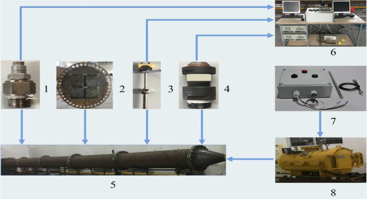
The explosion venting experiment was carried out with an independently built experimental system. The experimental system was divided into four parts as shown in Figure 1: (1) large-diameter explosion pipeline experimental system [5 and 8]; (2) high-performance data acquisition system [1, 3, 4, and 6]; (3) explosion venting door [2]; and (4) ignition control system [7].
Figure 1.
Schematic diagram of the experimental system: 1, pressure sensor; 2, explosion venting door; 3, temperature sensor; 4, speed sensor; 5, explosion pipeline; 6, computer and high-performance data acquisition system; 7, ignition control system; and 8, explosion tank.
2.1. Large-Diameter Explosion Pipeline Experimental System
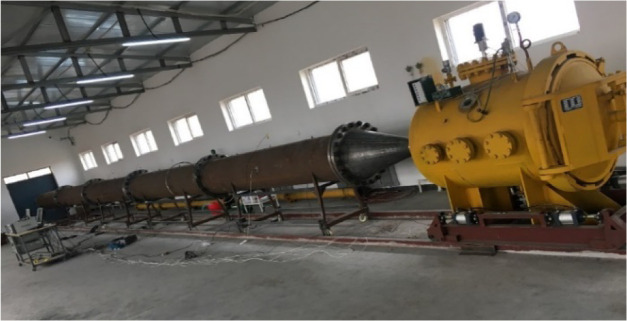
The large-diameter explosion pipeline experimental system included an explosion tank and an explosion pipeline, as shown in Figure 2. The explosion pipe had a total length of 17.5 m and an inner diameter of 0.61 m, which was a circular pipe with a length-to-diameter ratio of 29. The entire explosion pipeline was equally divided into five sections. A circular flange was used to connect adjacent pipelines, and a sealing ring was set in the middle of the flange to prevent leakage, the fifth section of the pipeline opens to the outdoors, and the pipeline was placed on the pulley bracket. The explosion tank simulated the spontaneous fire area and the explosion source, and the first and second sections of the pipeline simulated the mining face and the enclosed area in the roadway.
Figure 2.
Explosion experimental pipeline.
2.2. High-Performance Data Acquisition System
The high-performance data acquisition system composition was as follows. (1) The explosion pressure acquisition system adopted a 2200V1 piezoelectric high-sensitivity sensor manufactured by Dytran and PCI-1712L pressure data acquisition device. (2) The explosion flame temperature acquisition system adopted a DT9805 temperature data acquisition module and C2-7-K thermocouple produced in the United States. (3) The flame propagation velocity acquisition system used AD620 series operational amplifiers produced in the United States and D749 high-speed infrared phototubes produced in the United Kingdom. Explosion pressure, flame temperature, and flame propagation speed data were first collected by the corresponding high-speed data acquisition module, and finally the data was displayed and processed by the software installed on a computer.
The placement position of each measuring point sensor is shown in Figure 3. To collect the pressure signal, temperature signal, and speed signal more effectively, the sensor of the corresponding signal was arranged at the center of each section of the pipeline. Since only the pressure and temperature changes near the explosion venting door needed to be collected, four sets of pressure sensors and temperature sensors were respectively arranged in the middle positions on the left and right sides of the first four pipe sections, corresponding to the measuring points 1–4. Because the speed could not be displayed from time to time, the speed could only be measured in intervals, and five sets of speed sensors were arranged in the middle position on the upper side of each pipe section, corresponding to the measuring points 1–5. The horizontal distances between the measuring points 1–5 and the explosion tank were 1.75, 5.25, 8.75, 12.25, and 15.75 m, respectively.
Figure 3.
Sensor position and measuring points diagram.
2.3. Explosion Venting Door
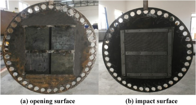
As shown in Figure 4, the explosion venting door was a circular steel plate placed in the middle of measuring points 2 and 3. With an outer diameter of 840 mm and a thickness of 15 mm, the door was fixed between the two pipelines by flanges and sealing iron rings. Four explosion venting windows of equal size were set in the middle of the explosion venting door. The opening and closing of the explosion venting window could play the role of explosion venting and sealing. To meet the damage resistance and reusability of the explosion venting door, it was designed according to “GB50017-2003 code for the design of steel structures”.
Figure 4.
Explosion venting door: (a) opening surface and (b) impact surface.
Figure 4a shows the opening surface of the explosion venting window when the explosion shock wave hits the explosion vent door. It pulls four rectangular sealing plates through four horizontal shafts. The rectangular sealing plates block four vents with a side length of 160 mm. To prevent the explosion vent window from leaking when it is closed, a sealing rubber ring is installed at the explosion vent window. Figure 4b shows the impact surface of the explosion shock wave. To make the explosion venting characteristics more obvious, a fire barrier is installed on this surface to prevent the flame from passing through the explosion venting device.
2.4. Ignition Control System
The ignition control system was equipped with an RXFD-20 explosion-proof remote control high-energy igniter, as shown in Figure 5. The igniter could control the remote control board at a safe distance. The ignition time could be controlled by pressing the ignition button of the remote control board. When the igniter started to ignite, the ignition indicator on the control box flashed for a countdown of 10 s. If there was a fire at the vent after 10 s, then the ignition was successful. If the ignition was not successful, the ignition stop button on the remote control board was pressed to reset and then the ignition button was pressed to re-ignite. After the ignition was over, the ignition stop button was pressed and the power switch on the right side of the remote control board was turned off.
Figure 5.
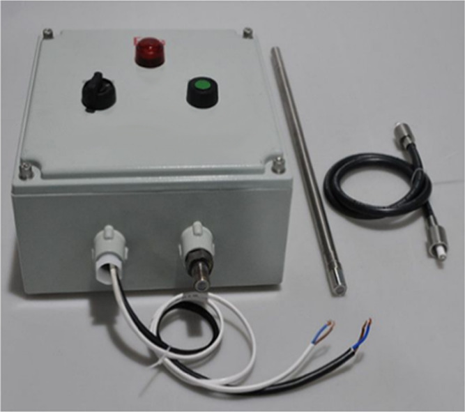
Explosion-proof remote control high-energy igniter.
2.5. Design of Experimental Conditions
The volume fraction of the methane–air premixed gas of 5.5, 7.5, 9.5, and 11.5% concentration was introduced into the explosion tank and the explosion venting door was placed at the same time. Explosion experiments were carried out under four different working conditions. The data of each measurement point were collected through the high-performance data acquisition system and the change characteristics of the gas explosion characteristic parameters and the explosion venting effect of the explosion venting door were analyzed.
Due to the short distance between measuring points 1 and 2 and measuring points 3 and 4, the propagation speed of the explosion shock wave was too fast, and the change rule and characteristic value of the explosive characteristic parameters of measuring points 1 and 2 and measuring points 3 and 4 were similar, Therefore, while analyzing the explosion venting characteristics of the explosion venting door and the change law of gas explosion characteristic parameters, only the measurement points 2 and 3 were selected for comparison and analysis.
2.6. Experimental Steps
The experimental process consisted of three parts: preliminary preparation of the experimental system, inspection of the experimental system, and detonation gas.
-
(1)
Preliminary preparation of the experimental system involved (1) preparing the high-concentration gas and detonation source for the experiment; (2) assembling the explosion pipeline and explosion tank, and installing the explosion venting door at the junction of the second and third pipelines; (3) according to the experimental system, installing the pressure sensor, speed sensor, and temperature sensor at the corresponding measuring points and recording the corresponding acquisition channels of the sensors at different measuring points.
-
(2)
Inspection of the experimental system included (1) checking whether the vacuum pump was working normally and whether the combustible gas pipeline was normally delivering gas; (2) turning on the power supply of the control system and checking whether the emergency button on the control system panel was sensitive and whether the valve of the vacuum digital display meter was closed; (3) checking whether the sensor circuit could collect normally; (4) turning on the power supply of the safety monitoring interlock system, and checking whether the vent ball valve and quick opening door on the explosion tank worked normally; (5) checking whether all valves were in a closed state; and (6) checking whether the pipe flange and sensor screws were tightened.
-
(3)
Gas was detonated by (1) using a vacuum pump to mix high-purity methane with high-purity air to form a 9.5% methane–air mixed gas according to Dalton’s law of partial pressure, (2) injecting 1 m3 of mixed gas into the explosion tank and controlling the acquisition module software of each measuring point to enter the ready state, and (3) using an explosion-proof remote-controlled high-energy igniter to ignite the ignition head and trigger an explosion.
3. Results and Discussion
3.1. Analysis of Rapid Sealing and Explosion Venting Characteristics of Explosion Venting Door
Figure 6 shows the change characteristics of the pressure with time at the measuring points 2 and 3 before and after the explosion venting door was released when the gas volume fraction is 9.5%. It can be seen from Figure 6a that there were only two peaks at 0.095 and 0.29 s in the pressure change curve at measuring point 2, and the peak at 0.095 s was the largest, with a peak value of 107 kPa. This was because the initial shock wave energy was not enough to open the explosion venting window, and part of the shock wave was rebounded and superimposed with the lagging shock wave. At this time, the explosion pipeline formed a closed space for a short time, so that the pressure in the closed space continued to increase. When the explosion venting window was opened, the first wave crest appeared in the change curve. It could be seen from the change curve that the negative pressure began to appear after 0.21 s, and the maximum negative pressure was −31 kPa and appeared at 0.236 s, followed by small fluctuations at 0.29 s, and the pressure began to reach a stable state after 0.35 s, and it had been in a negative pressure state for a long time, the change curve was shown in Figure 6b. Because the explosion shock wave passed through the explosion venting window instantly, the energy of the impact on the explosion venting window disappeared instantly and the explosion venting window was automatically closed by its own weight. At this time, there was a pressure difference between the enclosed area and the area outside of the explosion venting door so that the explosion venting door was firmly closed. The pressure at measuring point 3 was attenuated due to the opening of the explosion vent window by the shock wave, and part of the energy was attenuated. The wave crest dropped from 107 to 50 kPa, which was attenuated by 53.27%. After 0.4 s, the pressure curve oscillated and decreased until it became 0 kPa. At this time, all of the explosion shock waves in the pipeline rushed out of the pipeline.
Figure 6.
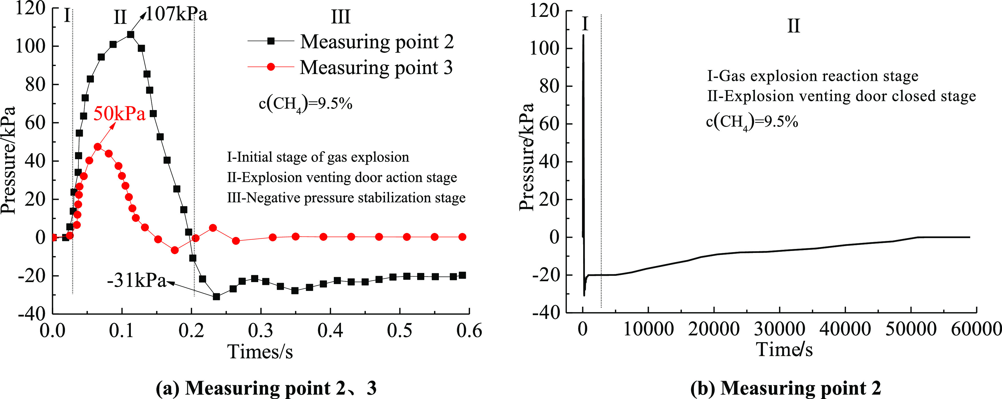
Variation of rapid sealing explosion release and sealing of explosion venting door: (a) measuring points 2 and 3 and (b) measuring point 2.
It can be seen from Figure 5b that the pressure in the enclosed area was kept at −20 kPa from the point of measurement 2 at 0.6 s. At the time of the gas explosion, a high-temperature and high-pressure environment was formed inside the pipeline to expand the volume of the sealing ring. After 6 s, the internal temperature of the pipeline dropped and the volume of the sealing ring shrank, causing it to slightly deform. Therefore, the negative pressure inside the pipeline in the “vacuum cavity” state continuously sucked in external air, and the pressure began to rise slowly. Finally, the enclosed area returned to normal pressure after about 13.89 h. After the experiment, the explosion venting door did not show any deformation, indicating that the explosion venting door had a good sealing performance.
3.2. Characteristics of Gas Explosion Pressure and Temperature Variation
3.2.1. Pressure Change Characteristics of Measuring Points 2 and 3
Figure 7 shows the pressure change characteristics of measuring points 2 and 3 with time under the action of an explosion venting door when the gas volume fractions are 5.5, 7.5, 9.5, and 11.5%. When propagating from measuring point 2 to measuring point 3, the maximum peak values dropped from 71, 93, 107, and 103 kPa to 41, 46, 50, and 48 kPa, which were attenuated by 42.25, 50.54, 53.27, and 52.88%, respectively. With an increase in the gas volume fraction, the pressure peak attenuation characteristic showed a quadratic function relationship, which increased first and then decreased. Measuring point 2 began to generate negative pressure at 0.17, 0.19, 0.202, and 0.195 s, and the average recovery time to positive pressure was 13 h, indicating that the closing time remained consistent.
Figure 7.
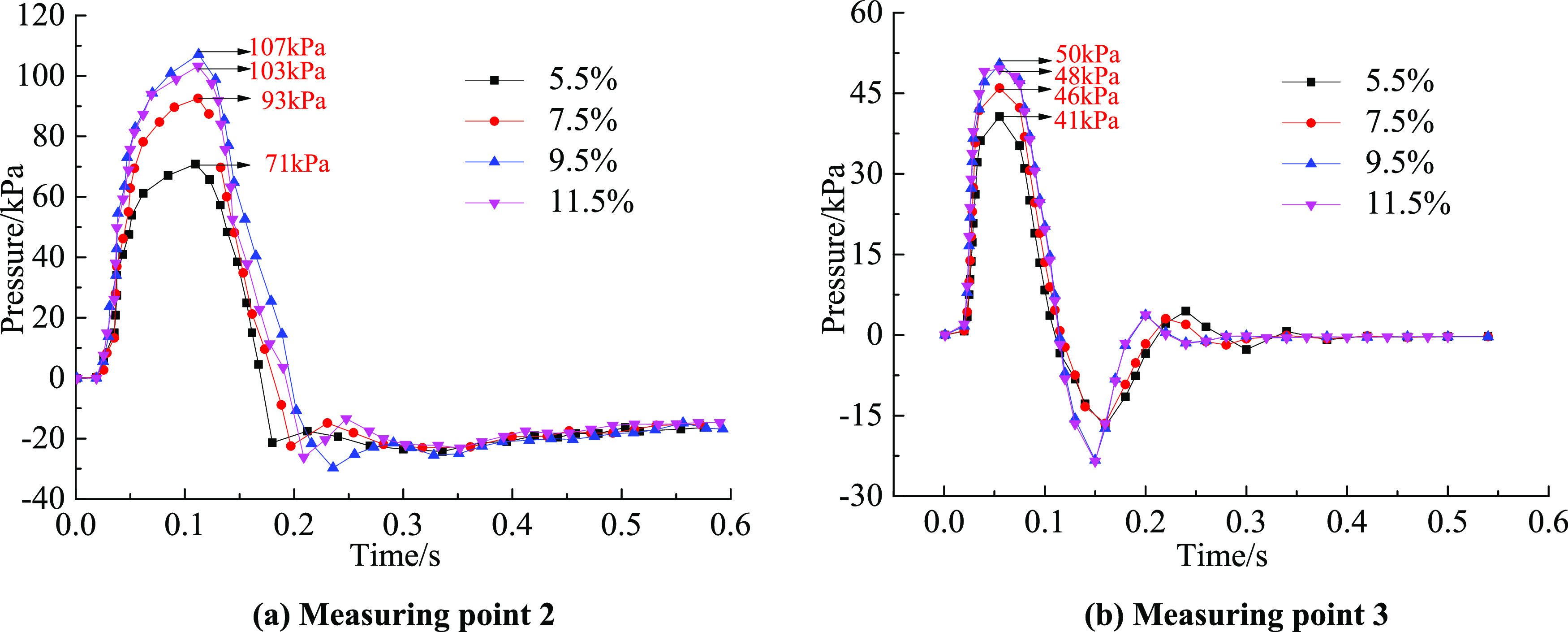
Variation of pressure with time under different working conditions at (a) measuring point 2 and (b) measuring point 3.
3.2.2. Temperature Change Characteristics of Measuring Points 2 and 3
Figure 8 shows the flame temperature change characteristics of measuring points 2 and 3 with time under the action of the explosion venting door when the gas volume fractions are 5.5, 7.5, 9.5, and 11.5%. From the change curves of the two measuring points, it can be seen that the characteristics of the curve change under different working conditions were basically the same. The temperature and time of the entire gas explosion propagation process were in a quadratic function. When the explosion flame passed through measurement point 3, the peak flame temperature was only slightly attenuated; no matter how the gas volume fraction changed, the explosion vent door had no effect on the explosion flame. Since there was no high-speed camera, it was impossible to capture the flame shape changes with time, so only the law of the flame temperature could be analyzed. In the follow-up, experimental methods similar to those in the literature47−49 are used to obtain the change law of the flame shape of the explosion vent door by shooting the flame pictures.
Figure 8.
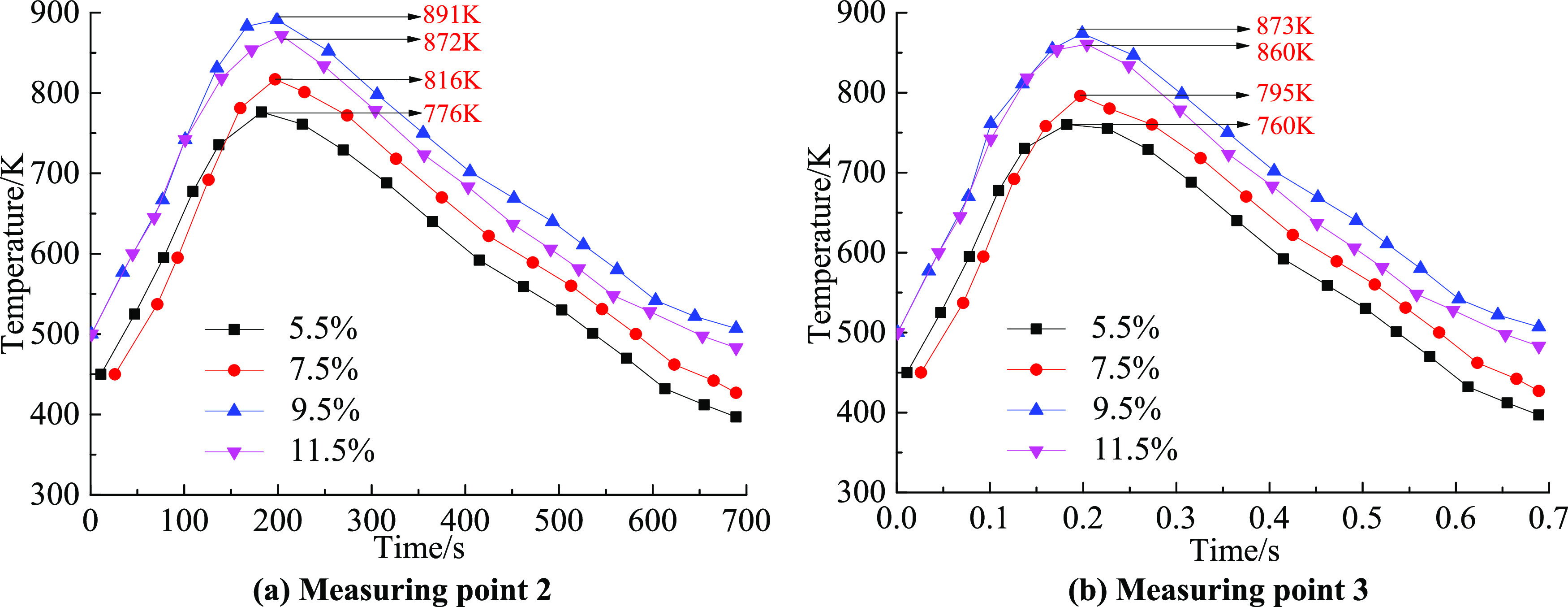
Variation of temperature with time under different working conditions at (a) measuring point 2 and (b) measuring point 3.
3.3. Variation Characteristics of Pressure Peak and Temperature Peak under Four Working Conditions
Figure 9 shows the change characteristics of the pressure peak and temperature peak at different measuring points when the gas volume fractions are 5.5, 7.5, 9.5, and 11.5% under the action of the explosion venting door. From the gas chemical reaction equation, it can be seen that the volume fraction is 9.5%, which is exactly reflected and the most violent. Therefore, the pressure peak and temperature peak change characteristics were analyzed with the volume fraction of 9.5% as an example.
Figure 9.
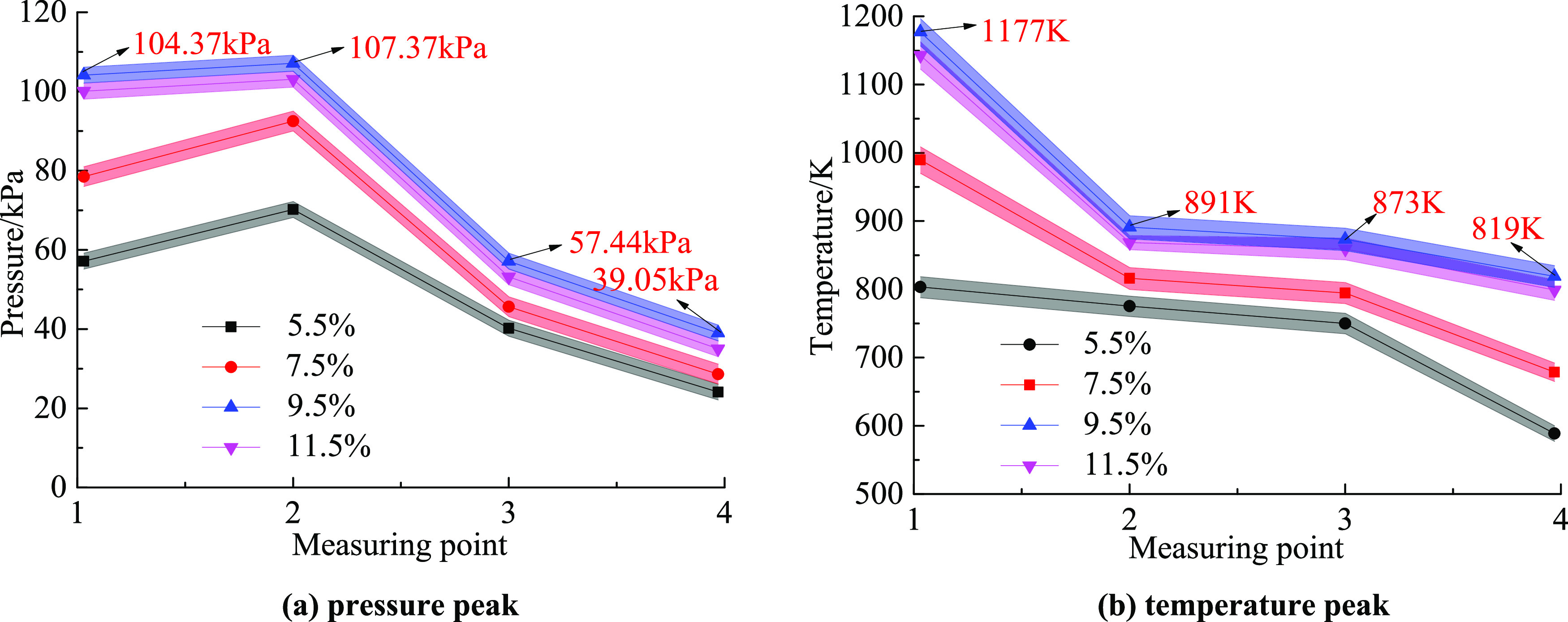
Variation of pressure peak and temperature peak under different concentrations and different working conditions: (a) pressure peak and (b) temperature peak.
3.3.1. Characteristics of Pressure Peak Changes
It can be seen from Figure 9a that the pressure peaks of measuring points 1–4 were 104.37, 107.37, 57.44, and 39.05 kPa, respectively. The peak pressure of measurement point 2 was 2.9% higher than that of measurement point 1. The peak pressure of measurement point 3 was 46.5% lower than that of measurement point 2. The peak pressure of measurement point 4 was 32.0% lower than that of measurement point 3. The pressure peak change curve showed a quadratic function relationship. This was because, in the early stage of the gas explosion, the explosion tank continuously released a large amount of energy; this was blocked by the explosion venting door, which caused the shock wave pressure in the enclosed area to increase continuously, resulting in the pressure peak of measuring point 2 to become greater than that of measuring point 1. Under the action of the explosion venting window, the shock wavefront and the flame wavefront were stretched and deformed, and part of the energy was consumed at the same time. At this time, the pressure peak of measuring point 3 was also much smaller than that of measuring point 1. In the process of shock wave propagation, the front gas was continuously heated while being subjected to the frictional resistance and heat dissipation of the pipe; then, the energy continued to decrease, so the pressure peak at measuring point 4 decreased again. In short, the energy loss during the propagation of the gas explosion was mainly due to the suppression by the explosion venting door. Due to the effect of explosion and heat dissipation, the intensity of the reaction gradually weakened, and the pressure peak decreased accordingly.
It can be seen from the pressure peak change curve that the peak pressure of each measuring point was the highest during the entire explosion propagation process in the 9.5% working conditions, while the explosive strength and peak pressure were between 7.5 and 9.5%, respectively, in the 11.5% working condition due to insufficient oxygen. In other working conditions, the maximum value of the gas explosion pressure peak appeared at measuring point 2, and the pressure peak change characteristics were consistent with those in the gas fraction of 9.5%.
3.3.2. Characteristics of Temperature Peak Changes
It can be seen from Figure 9b that the temperature peaks of measuring points 1–4 were 1177, 891, 873, and 819 K, respectively, and the temperature peaks of adjacent measuring points were dropped by 24.3, 2.0, and 6.2%, respectively. The peak temperature of measuring point 1 was the largest, and the temperature drop was the maximum from measuring point 1 to measuring point 2. This was because the high-temperature gas produced by the explosion tank propagated forward rapidly, and the overpressure generated at the moment of the explosion caused the temperature around measuring point 1 to increase rapidly, so the temperature peak of measuring point 1 was the largest. Because the high-temperature gas propagated forward and mixed with the gas around the measuring point 2 and the pipeline wall dissipated heat at the same time, the temperature peak eventually dropped significantly. When the explosion flame passed through the explosion venting window, a turbulent flame was formed due to the action of the obstacle. The flame wave was not in contact with the pipeline wall in a large area, and the temperature attenuation became weaker when it reached measuring point 3. As the flame continued to propagate forward, the flame began to contact the pipeline wall in a large area, resulting in a large loss of energy, and the temperature attenuation became stronger when it reached measuring point 4. The temperature peak change characteristics also showed that the temperature attenuation had nothing to do with the explosion venting door.
3.4. Characteristics of Gas Explosion Speed Variation
The flame propagation speed in this experiment was to record the time when the flame reached each measuring point and the distance between two adjacent measuring points through the infrared sensor. The average flame propagation speed vf between the two adjacent measuring points is
| 1 |
where t is the time difference between the flame reaching two adjacent infrared sensors (t) and L is the distance between the measuring points of two adjacent infrared sensors (m).
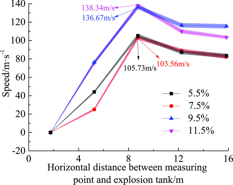
Table 1 and Figure 10 show the change characteristics of the flame average speed table and flame propagation speed at adjacent measuring points when the gas volume fractions are 5.5, 7.5, 9.5, and 11.5%, respectively.
Table 1. Average Flame Speed of Two Adjacent Measuring Points.
| average
speed (m·s–1) |
||||
|---|---|---|---|---|
| working condition (%) | section 1.75–5.25 m | section 5.25–8.75 m | section 8.75–12.25 m | section 12.25–15.75 m |
| 5.5 | 25.11 | 103.56 | 89.13 | 82.28 |
| 7.5 | 44.27 | 105.73 | 87.55 | 83.49 |
| 9.5 | 76.15 | 136.67 | 119.78 | 115.53 |
| 11.5 | 75.33 | 138.34 | 109.97 | 103.64 |
Figure 10.
Variation of average velocity in each velocity interval under different measuring conditions.
It can be seen from the characteristics of speed change in Figure 10 that the gas explosion state under the 7.5% working condition was more severe than that under the 5.5% working condition when the speed range was 1.75–5.25 m, and the speed under the 7.5% working condition was greater than that under the 5.5% working condition. However, the gas content in the later stage of the gas explosion was insufficient, and the chemical reaction energy supply was insufficient, which made the two velocity curves coincide in the velocity measurement range 12.25–15.75 m. When the 11.5% working condition was in the speed range of 1.75–5.25 m, the speed curve basically coincided with that in the 9.5% working condition, but the oxygen was lacking in the later stage of the gas explosion, and the gas activity was reduced. In the speed range of 12.25–15.75 m, the flame speed of the 11.5% working condition started to decrease. During the entire propagation process, the maximum speeds at the speed range of 5.25–8.75 m in the four operating conditions were 103.56, 105.73, 136.67, and 138.34 m/s, respectively. Since the flame hits and opens the venting windows when it reached the venting door, it lost some energy. The venting window could be regarded as an obstacle. The flame wave was disturbed by the venting window and traveled in a turbulent state. The interior of the flame wave did not contact the pipeline wall in a large area and began to accelerate for a short time, but the duration was short. As the flame continued to propagate forward, the flame began to contact the pipe wall in a large area, resulting in a large loss of energy, and the remaining energy was not enough to continue acceleration, resulting in a drop in the flame speed. Since the location of the explosion venting door was 7 m in the maximum speed range of 5.25–8.75 m, whether the explosion venting door had an effect on the flame propagation speed still needs further study.
4. Conclusions
To study the influence of the explosion venting door on the characteristic parameters of gas explosion and verify its explosion venting effect and fast sealing performance, we constructed a large-sized gas explosion pipeline experimental system and performed explosion experiments under four working conditions. The gas explosion characteristic parameters were collected through the data acquisition system, and the influence of the explosion vent door on the gas explosion pressure, flame temperature, and flame speed was analyzed. The conclusions were summarized as follows:
-
(1)
We independently developed a rapid closed explosion venting experimental system. Large-sized explosion pipelines and explosion venting devices were used to simulate the suppression effect of explosion venting doors on gas explosions when the fire zone was closed, which effectively made up for the lack of experimental research on small-sized pipeline explosions.
-
(2)
Under different working conditions, when the explosion shock wave propagated from measuring point 2 to measuring point 3, the pressure peaks were attenuated by 42.25, 50.54, 53.27, and 52.88%, respectively. As the gas volume fraction increased, the peak pressure of the explosion attenuated. The characteristics showed a quadratic function relationship, and the average closing time of the fire area was 13 h, which showed that the explosion venting door had significant explosion venting characteristics and the function of quickly closing the fire area.
-
(3)
The temperature change characteristics under different working conditions were basically the same. No matter how the gas volume fraction changed, the explosion venting door had no inhibitory effect on the gas explosion flame.
-
(4)
Under the four working conditions, the maximum average values of the flame propagation velocity appeared in velocity measurement interval 2 and were 103.56, 105.73, 136.67, and 138.34 m/s.
-
(5)
It can be seen from the pressure peak and the temperature peak change curves that the peak pressure and temperature peak of each measuring point were maximum during the entire explosion propagation process in the 9.5% working condition, while they were between 7.5 and 9.5% in 11.5% working condition due to insufficient oxygen and explosive strength. In other working conditions, the maximum values of pressure peak and temperature peak appeared at measuring point 2, and its change characteristics were consistent with those in the 9.5% working conditions.
-
(6)
This article has achieved some results in the rapid closed explosion venting technology, but the following issues still need to be explored and studied. (1) The experimental platform needs to be improved. Due to the limitation of the experimental system, the experimental speed can only be calculated by the distance between adjacent sensors and the time difference between the flame reaching the adjacent infrared sensor, thus affecting the accuracy of the experimental data and conclusions. Therefore, it is necessary to install a visible window that can observe the flame on the side of the explosion pipe and the high-speed cameras and a schlieren were used to observe the flame propagation process and pressure relief process more intuitively and to monitor the flame propagation speed in real-time. At the same time, a large-volume explosion tank that matches the explosion pipeline is replaced, which can make the explosion characteristics more obvious and the experimental data more accurate. (2) Follow-up research works are required. First, for the explosion venting mechanism of the explosion venting door, this article only conducted a preliminary study at the level of gas explosion characteristics. However, the force of the shock wave generated by the gas explosion on the explosion venting door needs to be further studied by ANSYS mechanics calculation software. Second, the explosion test of gas mixtures such as multi-alkanes will be supplemented. Under the conditions of different materials of explosion venting doors and different numbers of explosion venting windows, a closed explosion venting characteristic experiment is carried out, and the influence of explosion venting door on the law of gas explosion propagation is analyzed. Finally, the explosion venting door suitable for mines and industrial fields is designed and manufactured, and the actual objects are implemented in the experiment and field. At the same time, the performance of the explosion venting door is further verified and performance is optimized and improved.
Acknowledgments
A.L. received funding from the Fundamental Research Funds for the Central Universities (Grant no. 3142019006) and the Fundamental Research Funds for the Central Universities (Grant no. 3142018028). J.S. received funding from the National Natural Science Foundation of China (Grant no. 51804120).
Author Contributions
A.L. contributed to resources, software, writing, review, editing, project administration, and supervision. J.S. contributed to data curation, software, and writing the original draft. X.Z. contributed to review and editing.
The authors declare no competing financial interest.
References
- Gao Y.; Fu G.; Nieto A. A comparative study of gas explosion occurrences and causes in China and the United States. Int. J. Min., Reclam. Environ. 2016, 30, 269–278. 10.1080/17480930.2015.1043770. [DOI] [Google Scholar]
- Yin W.; Fu G.; Yang C.; Jiang Z.; Zhu K.; Gao Y. Fatal gas explosion accidents on Chinese coal mines and the characteristics of unsafe behaviors. Saf. Sci. 2017, 92, 173–179. 10.1016/j.ssci.2016.09.018. [DOI] [Google Scholar]
- Fu G.; Zhao Z.; Hao C.; Wu Q. The Accident Path of Coal Mine Gas Explosion Based on 24Model: A Case Study of the Ruizhiyuan Gas Explosion Accident. Processes 2019, 7, 73. 10.3390/pr7020073. [DOI] [Google Scholar]
- Ning F.; Cai M.; Wang Y.; Xu W.; et al. Research Progress of Related Technologies of Electric-Pneumatic Pressure Proportional Valves. Appl. Sci. 2017, 7, 1074 10.3390/app7101074. [DOI] [Google Scholar]
- Minggao Y. U.; Lei L. I. U.; Kai Z. Effect of spacing ratio between obstacle and pipe wall characteristics of gas explosion on propagation. J Saf. Sci. Technol. 2017, 13, 151–156. [Google Scholar]
- Yang C. L.; Yang C. Y.; Qi L. Research status and development direction of gas explosion. J. Saf. Sci. Technol. 2012, 8, 64–69. [Google Scholar]
- Zhang Y.; Zhou C.; Xie H.; Zhang Y. Structure optimization and flame barrier performance evaluation of barrier explosion-proof materials based on flacs. ChemistrySelect 2020, 5, 4947–4960. 10.1002/slct.201904965. [DOI] [Google Scholar]
- Yang G.; Huang W.; Feng S. Antiexplosion performance of engineered cementitious composite explosion-proof wall. Adv. Mater. Sci. Eng. 2020, 2020, 1–10. 10.1155/2020/1921960. [DOI] [Google Scholar]
- Medvedev S. P.; Anderzhanov E. K.; Guk I. V.; Ivantsov A. N.; Khomik S. V.; et al. Testing of explosion-proof coatings in cylindrical and conical shock tubes. Russ. J. Phys. Chem. B 2020, 14, 946–950. 10.1134/S1990793120060251. [DOI] [Google Scholar]
- Liu Z.; Song W.; Ji W.; Wen X. Experimental study on effects of explosion door mass on venting characteristics of gas deflagration. J. Therm. Sci. Technol. 2014, 13, 359–364. [Google Scholar]
- Xie C.Experimental and Numerical Simulation Research of Flame Propagation of Methane Explosion in a Pipe; Xi’an University and Technology: Xian, 2015. [Google Scholar]
- Zhang Y.; Wu Q.; LIU C.; Jiang B.; Zhang B. Experimental study on coal mine gas explosion suppression with inert gas N2/CO2. Explo and Shock Wave 2017, 37, 906–912. [Google Scholar]
- Fan X.; Li R.; Xue S. Experimental study on water curtain flameproof effect of gas explosion for coal mine. Min. Saf. Environ. Prot. 2011, 38, 17–19. [Google Scholar]
- Yang K.; Zhang P.; Xing Z.; et al. Experimental study on suppression of methane explosion with pultra-fine water mist containing both optimized methane oxidizing bacteria and inorganic salt. China Saf. Sci. J. 2019, 29, 62–67. [Google Scholar]
- Zhou X.; Li A.; Song D.; Chen M.; SUN B. Study on rapid sealing explosion-venting door in fire area of coal mine. J. Saf. Sci. Technol. 2016, 12, 125–129. [Google Scholar]
- Wang C.; Feng S.; Peng X.; Deng Y.; Chen J. Influence of opening mode on performance characteristics of nacelle pressure relief door. J. Aerosp. Power 2019, 34, 1069–1075. [Google Scholar]
- Pei B.; Wei S.; Chen L.; Pan R.; li J. Effect of CO2-ultrafine water mist on initial explosion characteristics of CH4/Air. Explo Shock Waves 2019, 39, 169–178. [Google Scholar]
- Yu M.; Zhu X.; Pei B.; et al. Experimental study on methane explosion suppression using carbon dioxide and ultra-fine water mist. J. China Coal Soc. 2015, 40, 2843–2848. [Google Scholar]
- Wei C.; Zhang B.; Jiang T.; et al. Discussion on Impact and Reduction of Mine Explosion Door. Coal Mine Mach. 2016, 37, 69–71. [Google Scholar]
- Gao N.; Jin I.; Huang X.; Zhang T.; Tao G. Study of airtight explosion-proof barrier system in a mine refuge chamber. Disaster Adv. 2013, 6, 241–249. [Google Scholar]
- Sun J.; Zhao J.; WEI C.; Zheng Q.; Zhang X. The porous-leak-pressure barrier explosion of the automatic air-door that is used in the mine. China Min. Mag. 2011, 20, 105–108. [Google Scholar]
- Shu Y.; Sun J.; Wei C.; Zhang X. Study of automatic air door of porous leaking pressure barrier explosion of mine. Coal Mine Mach. 2011, 32, 132–134. [Google Scholar]
- Zhang R.Mechanism and Numerical Simulation Research on Foam Ceramics; China University of Mining & Technology: Beijing, 2012. [Google Scholar]
- Rong J.; Hu S.; Yu C.; Liu D.; Zhou W. Development of auto-matic explosion suppression device for underground coal mine. Coal Eng. 2014, 46, 135–137. [Google Scholar]
- Sun Y.; Zhou X.; Bai G.; Li A.; Xin T.; Li D. Vent burst doors as an effective method of suppressing the dangers of gas explosions. AIP Adv. 2021, 11, 035112 10.1063/5.0033835. [DOI] [Google Scholar]
- Khelevina O. G.Fireproof materials with a vulcanised coating based on heteroorganic siloxane oligomers. Int. Polym. Sci. Technol. 2018.
- Wang X.; Shao D.; Ejeromedoghene O.; Qian K.; Wang Y.; et al. Preparation and study of fireproof materials with high-waterproof performance. Polym. Eng. Sci. 2020, 60, 1474–1481. 10.1002/pen.25394. [DOI] [Google Scholar]
- Argenti F.; Landucci G. Experimental and numerical methodology for the analysis of fireproofing materials. J. Loss Prev. Process Ind. 2014, 28, 60–71. 10.1016/j.jlp.2013.05.005. [DOI] [Google Scholar]
- Yan K.; Meng X.; Wang Z.; Xiao Q.; Ma X.; Cui Z. Inhibition of aluminum powder explosion by a NaHCO3/kaolin composite powder suppressant. Combust. Sci. Technol. 2020, 1–17. 10.1080/00102202.2020.1786377. [DOI] [Google Scholar]
- Yu M.; Wang X.; Zheng K.; Han S.; Wang L.; et al. Investigation of methane/air explosion suppression by modified montmorillonite inhibitor. Process Saf. Environ. Prot. 2020, 144, 337–348. 10.1016/j.psep.2020.07.050. [DOI] [Google Scholar]
- Ingram J. M.; Averill A. F.; Battersby P.; Holborn P. G.; Nolan P. F. Suppression of hydrogen/oxygen/nitrogen explosions by fine water mist containing sodium hydroxide additive. Int. J. Hydrogen Energy 2013, 38, 8002–8010. 10.1016/j.ijhydene.2013.04.048. [DOI] [Google Scholar]
- Sun Y.; Yuan B.; Chen X.; Li K.; Wang L.; Yun Y.; Ao F. Suppression of methane/air explosion by kaolinite-based multi-component inhibitor. Powder Technol. 2019, 343, 279–286. 10.1016/j.powtec.2018.11.026. [DOI] [Google Scholar]
- Zhang S.; Bi M.; Jiang H.; Gao W. Synergistic inhibition of aluminum dust explosion by gas–solid inhibitors. J. Loss Prev. Process Ind. 2021, 71, 104511 10.1016/j.jlp.2021.104511. [DOI] [Google Scholar]
- Wang L.; Liang Y.; Hu Y.; Hu W. Synergistic suppression effects of flame retardant, porous minerals and nitrogen on premixed methane/air explosion. J. Loss Prev. Process Ind. 2020, 67, 104263 10.1016/j.jlp.2020.104263. [DOI] [Google Scholar]
- Wang Y.; Meng X.; Ji W.; Pei B.; Lin C.; Feng H.; Zheng L. The inhibition effect of gas–solid two-phase inhibitors on methane explosion. Energies 2019, 12, 398. 10.3390/en12030398. [DOI] [Google Scholar]
- Zhou H.; Mu C. Influence of cavity width and powder filling in a cavity on overpressure evolution laws and flame propagation characteristics of methane/air explosion. ACS Omega 2021, 6, 10072–10084. 10.1021/acsomega.1c00054. [DOI] [PMC free article] [PubMed] [Google Scholar]
- Yan K.; Meng X. An investigation on the aluminum dustexplosion suppression efficiency and mechanism of a NaHCO3/DE composite powder. Adv. Powder Technol. 2020, 31, 3246–3255. 10.1016/j.apt.2020.06.014. [DOI] [Google Scholar]
- Liu R.; Zhang M.; Jia B. Application of gas explosion nanometer powder suppression material in coal mine safety. Integr. Ferroelectr. 2021, 217, 240–254. 10.1080/10584587.2021.1911317. [DOI] [Google Scholar]
- Liu R.; Zhang M.; Jia B. Inhibition of gas explosion by nano-sio2; powder under the condition of obstacles. Integr. Ferroelectr. 2021, 216, 305–321. 10.1080/10584587.2021.1911296. [DOI] [Google Scholar]
- Song Y.; Zhang Q. Quantitative research on gas explosion inhibition by water mist. J. Hazard. Mater. 2019, 363, 16–25. 10.1016/j.jhazmat.2018.09.059. [DOI] [PubMed] [Google Scholar]
- Yu M.; Yang X.; Zheng K.; Luan P. Progress and development of coal mine gas explosion suppression and disaster reduction technology in China. J. China Coal Soc. 2020, 45, 168–188. [Google Scholar]
- Wang C.; He X. Experimental study on the failure cause of suppression and isolation apparatus for gas explosion. China Saf. Sci. J. 2001, 11, 60–64. [Google Scholar]
- Liu H.; Wang Z. Technology of applying new material grouting to reinforce and block permanent closed wall. Min. Saf. Environ. Prot. 2013, 40, 87–90. 10.1016/j.ecoenv.2013.02.018. [DOI] [Google Scholar]
- Chen M.Experimental Study on Water Curtain of Explosion Suppression for Coal Mine Gas Explosion; Liaoning Technical University: Fuxin, 2017. [Google Scholar]
- Ma Z. Research status and development trend of explosion suppression technology in coal mine. Min. Saf. Environ. Prot. 2014, 41, 83–85. [Google Scholar]
- Liu J.; Li A.; Song C. Design of active firewall based on safety psychology. China Saf. Sci. J. 2005, 15, 88–91. [Google Scholar]
- Wang S.; Li G.; Guo H.; Li X.; Pu X.; Ren H.; Wu D. Experimental study on vented deflagration of hydrocarbon fuel-air mixtures in a 20-L semi-confined cylindrical vessel with a slight static activation pressure. J. Loss Prev. Process Ind. 2020, 64, 104091 10.1016/j.jlp.2020.104091. [DOI] [Google Scholar]
- Wang S.; Yan Z.; Li X.; Li G.; Guo H.; Wu D. The venting explosion process of premixed fuel vapour and air in a half-open vessel: An analysis of the overpressure dynamic process and flame evolution behaviour. Fuel 2020, 268, 117385 10.1016/j.fuel.2020.117385. [DOI] [Google Scholar]
- Qi S.; Du Y.; Wang S.; Zhou Y.; Li G. The effect of vent size and concentration in vented gasoline-air explosions. J. Loss Prev. Process Ind. 2016, 44, 88–94. 10.1016/j.jlp.2016.08.005. [DOI] [Google Scholar]


