Abstract
This study reports the phase transformation behaviour associated with electrolytic manganese dioxide (EMD) utilized as the positive electrode active material for aqueous zinc-ion batteries. Electrochemical techniques, including galvanostatic charge–discharge and rotating ring-disk electrode measurements, and microstructural techniques, using X-ray powder diffraction, scanning electron microscopy, and transmission/scanning transmission electron microscopy, were utilized to characterize the positive electrode at different stages of discharge and charge of zinc-ion cells. The results indicate that, during discharge, a fraction of EMD undergoes a transformation to ZnMn2O4 (spinel-type) and Zn2+ is intercalated into the tunnels of the γ- and ε-MnO2 phases, forming ZnxMnO2 (tunnel-type). When a critical concentration of Mn3+ in the intercalated ZnxMnO2 species is reached, a disproportionation/dissolution reaction is triggered leading to the formation of soluble Mn2+ and hydroxide (OH–) ions; the latter precipitates as zinc hydroxide sulfate (ZHS, Zn4(OH)6(SO4)·5H2O) by combination with the ZnSO4/H2O electrolyte. During charge, Zn2+ is reversibly deintercalated from the intergrown tunneled phases (γ-/ε-ZnxMnO2), Mn2+ is redeposited as layered chalcophanite (ZnMn3O7·3H2O), and ZHS is decomposed by protons (H+) formed during the electrochemical deposition of chalcophanite.
Subject terms: Batteries, Batteries, Electrochemistry, Electrochemistry
Introduction
Manganese-based oxides, because of their low cost, low toxicity and their relatively high reduction potentials, have received widespread attention since the 1990s in the field of electrochemical energy storage, such as supercapacitors, pseudocapacitors, primary batteries, rechargeable metal-air batteries, and Li-ion batteries (LIBs)1–4. The remarkable diversity of atomic architectures has provided manganese (Mn) oxides the ability to accommodate a wide variety of metallic cations. Rechargeable Zn-ion batteries (ZIBs) using a mild aqueous electrolyte offer the potential for a cheaper and safer choice relative to LIBs for stationary energy storage systems. As such, recent efforts have been made to employ Mn oxides as active materials for positive electrodes of ZIBs. Multifarious Mn oxides have been utilized as positive electrodes in ZIBs, including α-MnO2 (2 × 2 tunnels)5–10, β-MnO2 (1 × 1 tunnels)11–13, γ- or ε-MnO2 (1 × 1 and 1 × 2 tunnels)14–17, todorokite (3 × 3 tunnels)18, δ-MnO2 (layered structure)19,20, and other Mn oxides with different oxidation states such as Mn2O321,22, Mn3O423,24, and ZnMn2O425. Manganese dioxides (MnO2) used in energy storage devices are generally classified into three categories based on their origin including natural MnO2 (NMD), chemical MnO2 (CMD), and electrolytic MnO2 (EMD)26. NMD is the only one obtained from natural ores. It is a mixture of several Mn oxide minerals (up to 20 different types) and has lower and inconsistent performance compared with the other two forms26. Between the two synthesis pathways, electrochemical deposition methods are known to be superior to chemical synthesis methods, as the purity and properties of the deposited material are better controlled27. Thus, in commercial batteries, EMD is predominantly used and is likely to remain the preferred energy material for the foreseeable future27. Given the widespread usage of EMD in existing commercial batteries, along with its low-cost and established supply chains, EMD is worth exploring for less developed energy storage systems such as ZIBs.
Although several studies have been done to investigate Mn oxides, the storage mechanisms with respect to their electrochemical performance in ZIBs remain ambiguous. Generally, most papers report that Zn2+ is inserted into both tunneled and layered MnO2, but the detailed mechanisms during discharge and the stability of the structures have not been thoroughly examined28,29. The literature has also suggested that H+ insertion to form MnOOH during discharge may occur solely9, simultaneously28, or sequentially29 with Zn2+ insertion. Some studies have suggested that the formation of MnOOH occurs first and is followed by dissolution of highly soluble Mn2+ by electrochemical reduction (MnOOH + H2O + e− → Mn2+ + 3OH–)30 or chemical disproportionation (2MnOOH → Mn2+ + MnO2 + 2OH–)9 and that there is no Zn2+ insertion. On the other hand, it has been reported that Mn4+ in MnO2 is reduced to Mn3+ upon electrochemical intercalation of Zn2+ and the resulting Mn3+ compound is disproportionated into Mn4+ and Mn2+ (2Zn0.5MnO2 + 2H2O → Zn2+ + Mn2+ + MnO2 + 4OH–)31.
The purpose of this study is to investigate the mechanisms associated with the use of EMD as the positive electrode in aqueous ZIBs. Cycled batteries are disassembled to characterize the EMD electrodes at different potential stages using X-ray powder diffraction (XRD), scanning electron microscopy (SEM) and transmission/scanning transmission electron microscopy (TEM/STEM). The results are compared with and supported by electrochemical measurements, including galvanostatic charge–discharge and rotating ring-disk electrode tests. The results indicate that the discharge/charge mechanism is quite complex and is likely the reason for such contradictory reports in the past9,28–31. Briefly, there is reversible Zn2+ intercalation into the tunnels of γ-/ε-MnO2 (in EMD) in addition to dissolution/precipitation side reactions.
Results and discussion
Electrolytic manganese dioxide
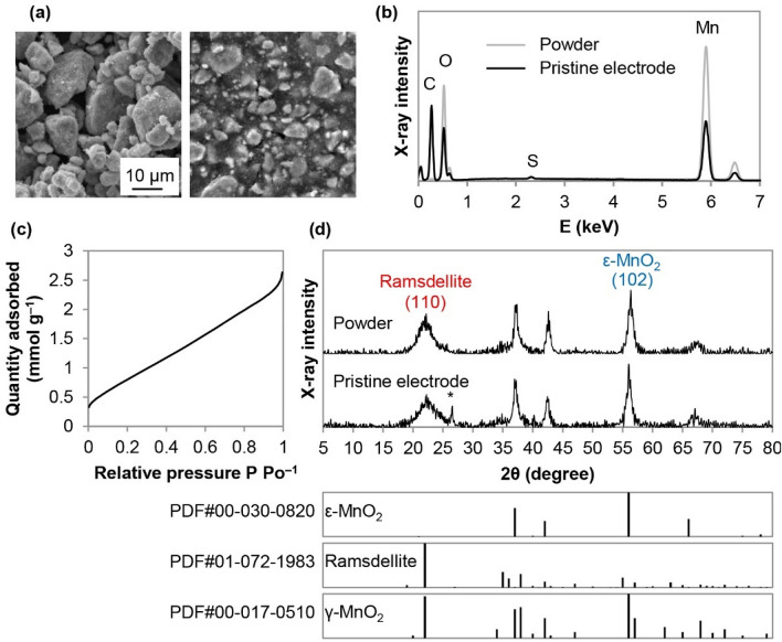
The morphology and composition of the EMD powder and pristine electrodes are shown in Fig. 1a and b. SEM images show that the EMD particle size, prior to electrode fabrication, is generally ≤ 10 μm. It is clear from the EDX data that the composition of the pristine electrode is similar to that of raw EMD; the carbon peak in the electrode is from carbon black and/or the graphite substrate used as a current collector for these electrodes. The Brunauer–Emmett–Teller (BET) specific surface area of EMD powder, determined from the nitrogen adsorption isotherm (Fig. 1c), is ~ 72 m2 g–1. As shown in Fig. 1d, the XRD patterns from the EMD powder and the electrode are quite similar. The peaks can be indexed to a mixture of three phases: akhtenskite (ε-MnO2), ramsdellite, and nsutite (γ-MnO2). These MnO2 polymorphs have MnO6 octahedra as the basic building block, which are assembled by sharing edges and/or corners to form tunneled structures. Ramsdellite has a (1 × 2) tunnel structure, while both γ-MnO2 and ε-MnO2 have intergrown (1 × 1) and (1 × 2) tunnels from pyrolusite and ramsdellite, respectively. In general, ε-MnO2 has a more disordered structure than γ-MnO232. Rietveld refinement, using Jade Pro software, was utilized to determine approximate EMD phase compositions. The EMD powder is composed of about 53% ε-MnO2, 34% ramsdellite, and 13% γ-MnO2. The result is in agreement with other reports in the literature indicating that EMD usually contains large amounts of ε-MnO2 (~ 50%) and ramsdellite (~ 40%), with a smaller amount of γ-MnO2 (~ 10%)33. Many of the XRD peaks for the three phases overlap, but the peaks at 22.1° and 56.1° are likely primarily from ramsdellite and ε-MnO2, respectively.
Figure 1.
(a) SEM secondary electron (SE) images of the EMD powder (LHS) and pristine EMD electrode (RHS). (b) EDX spectra from the entire image areas shown in (a). (c) Nitrogen adsorption isotherm for the EMD powder. (d) XRD patterns, along with powder diffraction files (PDFs) for ε-MnO2, ramsdellite, and γ-MnO2. The asterisk indicates a graphite peak from the current collector.
Galvanostatic cycling of EMD electrodes
Figure 2 shows voltage profiles with points indicating where EMD electrodes were extracted and characterized. For cycling the zinc-ion Zn||EMD cells, a constant current (CC) was used for discharge and a constant current–constant voltage (CC–CV) protocol was used for charge in the voltage window of 0.9 V to 1.8 V. The typical specific capacity for these cells was roughly half that of the theoretical value of 308 mAh g–1 for a one electron reaction (Fig. 2), indicating that there is a significant amount of inaccessible active material and only ~ 0.5 e− is actually transferred. This is likely due to the mixture of phases in EMD (Fig. 1) which lacks long-range order and disrupts diffusion of Zn2+ in the tunnels of ramsdellite, ε-MnO2, and γ-MnO2. The specific capacity is well known to be dependent on the crystallographic phase of MnO2 in zinc-ion cells34. The specific capacity is also very dependent on other parameters such as particle size and the effective surface area, which is associated with pore size distribution and pore volume35,36. Higher surface areas can enhance the battery capacity; however, the dissolution rate is also increased36,37. For practical battery systems, areal capacity is a more relevant metric that depends on the thickness and porosity of the electrode coating. Although the specific capacity is relatively low for EMD, the high loading electrodes used in this study result in areal capacities of 4–5 mAh cm–2.
Figure 2.
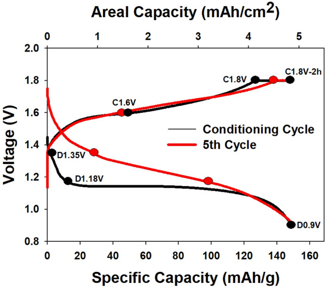
Discharge/charge voltage profiles for the first and fifth cycles of a Zn||EMD cell showing where electrodes were extracted for characterization.
For the characterization of electrodes discussed below, cells were stopped at three points during discharge (1.35 V, 1.18 V, and 0.9 V) and three points during charge (1.6 V, 1.8 V, and after the CV step at 1.8 V) for the first conditioning cycle and the fifth cycle. The CV step typically lasted for 2 h which is why it is labelled C1.8 V-2 h.
Several studies have increased the charging potential to 1.9 V20,38,39 and even to 2 V18,40; however, this will result in the oxygen evolution reaction (OER) at the positive electrode. Therefore, galvanostatic charge–discharge (GCD) tests with the charging potential limited to 1.8 V, followed by a constant voltage period, can alleviate the OER issue.
Dissolution of Mn2+
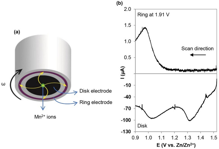
A rotating ring disk electrode (RRDE) was used to study the electrochemical reactions of the EMD electrodes, specifically to detect soluble Mn2+ species formed during discharge. Linear sweep voltammetry (LSV) was performed on the disk where generated products (in the form of soluble Mn2+ here) are swept outward by convection caused by rotation and can be detected electrochemically at the ring (Fig. 3a). The ring electrode was held at constant voltage (1.91 V vs. Zn/Zn2+) to oxidize the soluble Mn2+ to MnO2 (Mn2+ + 2H2O → MnO2 + 4H+ + 2e−). In Fig. 3b, two clear reduction peaks for EMD on the disk electrode are observed, although the current on the ring electrode only increases after scanning below ~ 1.1 V indicating that Mn2+ is formed/dissolved at lower voltages during the discharge process. Several Mn2+ dissolution pathways have been proposed in the past9,30,31, all accompanied with the formation of hydroxide species; however, the disproportionation reaction is observed here for EMD. As the Mn4+ in MnO2 is reduced to Mn3+ upon electrochemical intercalation of Zn2+, the resulting Mn3+ compound is disproportionated into Mn4+ and Mn2+ (2Zn0.5MnO2 + 2H2O → Zn2+ + Mn2+ + MnO2 + 4OH−)31. In the next section, through XRD and selected area electron diffraction (SAED) analysis, both intercalated ZnxMnO2 and spinel phase hetaerolite (ZnMn2O4) are found to form during the discharge process. As shown in Figure S1, hetaerolite formation is independent of potential and is stable during discharge, while intercalated ZnxMnO2 is unstable due to the Jahn–Teller effect and undergoes disproportionation.
Figure 3.
RRDE analysis of EMD. (a) Schematic diagram of RRDE tip. (b) RRDE profiles of EMD recorded at 1 mV s–1 in an Ar-saturated 1 M ZnSO4 solution, stirred at 900 rpm with the Pt ring maintained at 1.91 V versus Zn/Zn2+.
Solid phase identification
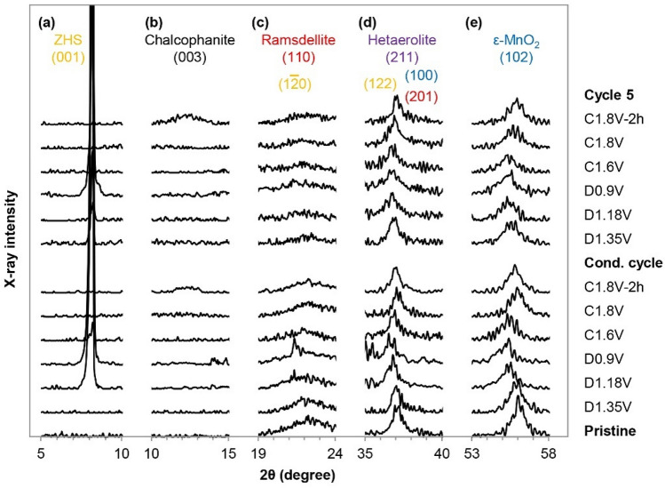
To examine the reaction mechanisms further, all EMD electrodes were analyzed by ex-situ XRD (Figure S2). In an effort to make the analysis clearer and to provide evidence for the overall scheme, the patterns are separated into different angular ranges in Fig. 4.
Figure 4.
XRD patterns of EMD electrodes at different potentials during GCD tests with the conditioning cycle at 0.5 mA cm–2 and the 5th cycle at 1 mA cm–2. The chosen peak ranges are representive of (a) ZHS, (b) chalcophanite, (c) ramsdellite, (d) hetaerolite, and (e) ε-MnO2.
One of the most interesting discoveries of this study lies in the fact that ramsdellite and ε-MnO2 in EMD behave differently during cycling. For both the conditioning and the 5th cycles, the major peak ((102) plane) for ε-MnO2 at 56.1° shifts to a lower angle of 55.1° at full discharge (0.9 V) (Fig. 4e). In fact, all other major ε-MnO2 peaks ((100), (101) and (110), originally at 37.1°, 42.5° and 67.0°, respectively) shift to lower angles during discharge. The peak shifts indicate an increase in both the a and c lattice parameters leading to expansion of the lattice structure. The a lattice parameter increases from 0.2797 to 0.2830 nm (1.18% increase), while the c lattice parameter increases from 0.4457 to 0.4543 nm (1.93% increase), with an overall cell expansion of 4.36%. The peaks shift back to their original positions after charging, meaning that the structure of ε-MnO2 can expand and collapse reversibly to accommodate Zn2+ ions. Since larger tunnels are favorable to store and transfer metallic ions without steric hindrance41, it is postulated that the (1 × 1) part of the intergrown network is less likely to participate in Zn2+ insertion while keeping the structure intact. The XRD results indicate the insertion of Zn2+ into the tunnels of ε-MnO2 (and possibly for γ-MnO2), which seems to occur gradually as the potential varies from open circuit potential to 0.9 V and is reversible during charging. The reaction can be written as follows:
| Reaction 1 |
The XRD results were not able to confirm the formation of hetaerolite (with the main peak at ~ 36.5°) during discharge due to interference from both MnO2 and ZHS peaks (Fig. 4d). However, the presence of hetaerolite was confirmed through TEM/STEM analysis (see subsequent paragraphs, Fig. 5).
Figure 5.
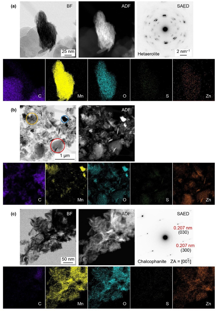
STEM bright field (BF) and annular dark field (ADF) images, EDX maps and SAED patterns from the EMD electrodes at different stages during cycling. (a) Electrode discharged at 1.35 V during the conditioning cycle, (b) electrode charged at 1.8 V during the 5th cycle, and (c) fully charged electrode held for 2 h at 1.8 V during the 50th cycle.
The major peak for ramsdellite at 22.1° (Fig. 4c) continuously decreases in intensity during discharge and does not recover after subsequent cycles. Instead, a new, broad peak emerges at ~ 12° (Fig. 4b) after charging and maintaining the potential at 1.80 V for 2 h. This peak corresponds to a hydrated Mn-Zn oxide phase known as chalcophanite (ZnMn3O7·3H2O). Thin film-XRD (TF-XRD) was used to examine the surface of the fully charged electrode and the new peak is shown with a better signal-to-noise ratio and higher intensity compared with the powder XRD results (Figure S3). Instead of having a tunnel structure like the starting material, chalcophanite is analogous to birnessite with a layered MnO6 octahedral structure containing ZnO6 interlayers42,43. The transformation of the tunneled structure or the electrodeposition of Mn2+ to form a layered birnessite-like structure has been reported previously31,44,45. In addition, Post et al. showed the structural similarities between the chalcophanite, anhydrous chalcophanite, and hetaerolite46. It is postulated that the dissolved Mn2+ ions formed during discharge are redeposited during charge, converting hetaerolite to chalcophanite. The reaction can be written as follows:
| Reaction 2 |
In Fig. 4a, the peak located at 2θ = 8.1° increases in intensity as the potential decreases from 1.18 to 0.9 V and is assigned to zinc hydroxide sulfate (ZHS). The best fit for the ZHS phase is Zn4(OH)6(SO4)⋅5H2O. The proposed pathway of Mn2+ dissolution (2Zn0.5MnO2 + 2H2O → Zn2+ + Mn2+ + MnO2 + 4OH–) results in the formation of hydroxide ions (OH–) which increase the local pH and lead to the undesired formation of layered double salts with a composition that is dependent on the electrolyte salt. In the present work, where aqueous zinc sulfate electrolyte is used, the precipitation product is ZHS (Reaction 3). ZHS has a layered structure consisting of stacked Zn(OH)2 sheets with the interlayer spaces filled with ZnSO4 as well as water molecules (Zn4(OH)6(SO4)⋅z H2O or also known as ZnSO4.3Zn(OH)2⋅z H2O, with z = 1/2, 1, 3, 4, and 5)47. The interlayer distance varies significantly depending on the hydration state, but is typically in the range of 7–11 Å48.
| Reaction 3 |
The Pourbaix diagram (Figure S4) clearly indicates that pH changes can lead to the formation of ZHS, which significantly increases the battery internal resistance49. However, it is admittedly difficult to detect the pH change in the vicinity of the electrode surface since ZHS acts as a buffer when forming and dissolving in the presence of OH– and H+, respectively. The ZHS peak intensity decreases during charging and disappears at 1.8 V and ZHS formation is suppressed during later cycles (Fig. 4a). The disappearance of the ZHS during charge is a direct result of the protons produced from Reaction 2:
| Reaction 4 |
Research on the battery reaction mechanisms has been hampered by the fact that the crystal structures for many of the Mn oxide phases are similar and, further increasing the difficulty of analysis, the products forming on the electrodes are often fine-grained, poorly crystalline mixtures. Thus, samples were examined using TEM/STEM to compliment the XRD results. The electrode discharged at 1.35 V during the conditioning cycle is shown in Fig. 5a, including an example of an SAED pattern from the polycrystalline particle shown. The pattern was indexed to hetaerolite (ZnMn2O4) (Table S1). The EDX maps (Fig. 5a) indicate that the Zn signal overlaps with the Mn and O signals, which confirms that Zn2+ is readily inserted into MnO2 during the first stage of discharge at 1.35 V. There is also a weak S signal which is residue from electrolyte overlaps with the particle.
STEM images and EDX maps of the EMD electrode after charging to 1.8 V (5th cycle) are shown in Fig. 5b. Three distinct regions are visible: Mn–O regions similar to the pristine EMD (blue circle), Mn-Zn–O regions which are hetaerolite and/or chalcophanite (yellow circle), and Zn–S–O regions which are residual ZHS (red circle). If battery charging is stopped at this stage and the battery is subsequently discharged, ZHS would accumulate and increase the battery internal resistance significantly. These results show that extending the charging time at 1.8 V is necessary to completely remove ZHS.
STEM images and EDX maps for the EMD electrode charged at 1.8 V and held for 2 h are shown in Fig. 5c. The Mn, O, and Zn signals in the EDX maps strongly overlap, while S signal is much weaker. Several SAED patterns were obtained (one example is shown here) and indexed to chalcophanite. According to the EDX analysis of the region in Fig. 5c, the Mn/Zn ratio in chalcophanite is ~ 2.5.
Morphology changes during discharge/charge
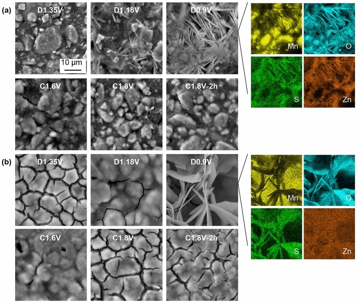
SEM and EDX analysis, shown in Fig. 6, were used to monitor the morphology evolution of the EMD electrodes during the charge/discharge processes. During the first discharge (Fig. 6a), the electrode surface was gradually covered with ZHS flakes which indicates an increased amount of OH– near the electrode surface at 1.18 V. During charging, the amount of ZHS is reduced and the EMD surface recovers. For the 5th cycle (Fig. 6b), ZHS appears at a potential lower than 1.18 V during discharge. Since a higher Mn2+ concentration is already available in the electrolyte, Mn4+ dissolution is reduced thereby delaying ZHS formation in subsequent cycles. This is the main reason for adding manganese sulfate (0.1 M MnSO4) to the electrolyte20. The electrode surface morphology changes drastically compared with the pristine electrode or the initial charge/discharge process. Although ZHS formation is reversible, the EDX maps show that Zn seems to have covered the electrode surface and the Zn signal overlaps with the Mn signal for subsequent cycles rather than just appearing in the ZHS region. The surface of the EMD electrode after 50 cycles is shown in Figure S5, confirming that the electrode surface is covered with a new layered material of Zn–Mn oxide. The XRD results (Fig. 4) showing the formation of chalcophanite after full charge correlate well with the SEM images and EDX mapping (Fig. 6) of the Mn-Zn oxide layer that forms and builds up on the EMD electrode surface during cycling.
Figure 6.
SEM SE images of EMD electrodes at different potentials during cycling tests. (a) Conditioning cycle at 0.5 mA cm–2 and (b) the 5th cycle at 1 mA cm–2. EDX maps for the D0.9 V images. Discharge and charge processes are denoted as D and C, respectively.
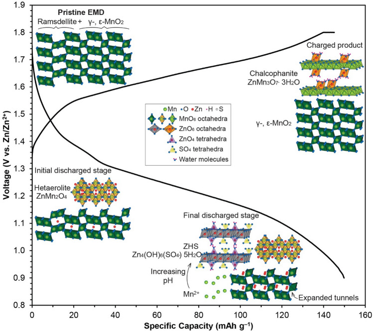
The results indicate that during the early discharge stage (Fig. 7), a portion of EMD undergoes transformation to spinel-type ZnMn2O4, while Zn2+ ions are also inserted into the (1 × 2) tunnels of γ-/ε-MnO2 to form tunnel-type γ/ε-ZnxMnO2 at early depths of discharge (Fig. 4e). The structure of γ/ε-ZnxMnO2 further expands, as more Zn2+ ions are added into vacant tunnels, until the end of discharge. During the final discharge stage, disproportionation of intercalated ZnxMnO2 occurs which causes ZHS formation. Upon charging, tunnel-type γ/ε-ZnxMnO2 reverts almost entirely to the original γ- / ε-MnO2, while dissolved Mn2+ is redeposited with hetaerolite as layer-type chalcophanite.
Figure 7.
Schematic illustration of the proposed charge/discharge process for EMD.
Conclusions
In this study, the electrochemical behaviour and structural changes for electrolytic manganese dioxide (EMD), utilized as a potential positive electrode for Zn-ion batteries (ZIBs), have been investigated. The initial EMD powder is composed of about 53% ε-MnO2, 34% ramsdellite, and 13% γ-MnO2. ZIBs using EMD have a multi-step reaction mechanism, which was confirmed by rotating ring-disk electrode (RRDE) analysis, X-ray diffraction (XRD), and electron microscopy. During discharge, Zn2+ ions are either intercalated to form spinel-type ZnMn2O4 or inserted into tunnels of MnO2 to form tunnel-type ZnxMnO2. The latter is unstable and once the saturation point for Zn2+ intercalation in the MnO2 tunnels (Zn0.5MnO2) is reached, Zn0.5MnO2 is disproportionated which results in zinc hydroxide sulfate (ZHS) formation. Electron microscopy and XRD analysis provided evidence of reversible ZHS formation and Zn2+ de-insertion. However, Mn2+ is electrochemically deposited back on hetaerolite to form chalcophanite. During cycling, the original ramsdellite portion of EMD disappears while layered chalcophanite gradually covers the electrode surface during charging. The electrochemical and chemical reactions are as follows:
During discharge:
| Hetaerolite formation | |
|---|---|
| Zn2+ insertion | |
| Disproportionation | |
| ZHS formation |
During charge:
| Deintercalation of Zn2+ | |
|---|---|
| Chalcophanite formation | |
| ZHS dissolution |
Methods
Preparation of EMD electrodes
All chemicals were used as received without further purification. EMD was obtained from Borman Specialty Materials (formerly Tronox).
In order to obtain a sufficient amount of cycled material for characterization, highly loaded EMD electrodes were prepared using a proprietary slurry cast method described elsewhere50. The mass loading of EMD was approximately 30–35 mg cm–2 on a graphite foil current collector.
Electrochemical measurements
For rotating ring-disk electrode (RRDE) experiments, a Pine Research rotator (model: AFMSRCE), rotating electrode controller, and fixed disk RRDE tip were used. The working RRDE tip consisted of a 4.57 mm diameter glassy carbon electrode and a Pt ring electrode with a 180 μm gap between them. The collection efficiency of this geometry is 22%. The ink composition contained 75 µL Nafion, 7.5 mg carbon black, and 7.5 mg of MnO2 (EMD) in 5 mL of 20% v/v of isopropyl alcohol (IPA). The ink (200 µL) was dropped on the disk electrode several times. The counter electrode was a Pt wire, while the reference electrode was Hg/HgO. The RRDE assembly was operated at 900 rpm with Ar saturation of the electrolyte. The disk electrode was scanned from OCV to 0.9 V at 1 mV s−1, while the Pt ring was kept at 1.91 V to ensure that any soluble Mn2+ species were oxidized back to Mn4+. All potentials in this study are referenced to Zn/Zn2+, obtained by adding the measured values to 0.86 V (VHg/HgO = 0.098 V and VZn/Zn2+ = − 0.762 V vs. NHE).
Zinc sulfate heptahydrate (ZnSO4·7H2O) was purchased from Sigma-Aldrich for use in the electrolyte. Deionized water (DIW) was used to rinse electrodes and prepare electrolytes.
All electrochemical cells were assembled using a homemade plate design comprising a rubber gasket sandwiched between two acrylic plates50. The acrylic plates were bolted together and housed the electrode stack (negative/separator/positive). The electrode stack was compressed together between Ti plates by external screws (torque of 2 in-lb) which also served as electrical connections. Zn foil (from McMaster-Carr) was used as the negative electrode and three layers of filter paper (Whatman #1) soaked with 1 M ZnSO4 were used as the electrolyte and separator between the EMD and Zn electrodes. Electrochemical measurements were carried out with Biologic SP-300 and VSP-300 potentiostats. During the charging process, the batteries were held at 1.8 V for an additional 2 h or until the current density dropped to 8 µA mg–1, whichever came first.
Materials characterization
The morphologies and compositions of the EMD samples were characterized using a scanning electron microscope (Tescan Vega3 SEM), coupled with an energy dispersive X-ray (EDX) spectrometer. X-ray diffraction (XRD) analysis was performed using a Rigaku Ultima IV diffractometer with monochromatic Cu Kα X-radiation (wavelength equal to 1.54 Å) at a scan rate of 5° min–1. Transmission/scanning transmission electron microscopy (TEM/STEM), X-ray microanalysis, and selected area electron diffraction (SAED) were performed using a JEOL JEM-ARM200CF TEM/STEM operating at an accelerating voltage of 200 kV. TEM/STEM samples were prepared by scraping the electrode surface and placing the residue into 1 mL of IPA. The suspension was sonicated for 30 min and one or two drops were placed onto a lacey carbon TEM grid. Nitrogen adsorption isotherms were measured at 77 K using a Micromeritics ASAP 2020 system. The EMD powder was outgassed at 200 °C for 12 h prior to any measurements. The BET method was used to measure the specific surface area of the sample at a relative pressure ranging from 0.05 to 0.30.
Supplementary Information
Acknowledgements
This work was supported by the International Manganese Institute (IMnI) and a grant through the Mitacs Accelerate program (FR49801). The authors are grateful to Professor Arvind Rajendran for access to the Micromeritics ASAP 2020 system.
Author contributions
S.J. fabricated the pristine EMD electrodes. T.N.T.T. characterized the materials and zinc ion batteries. D.G.I. contributed to the TEM characterization. The manuscript was written through contributions of all authors. All authors have given approval to the final version of the manuscript.
Competing interests
The authors declare no competing interests.
Footnotes
Publisher's note
Springer Nature remains neutral with regard to jurisdictional claims in published maps and institutional affiliations.
Supplementary Information
The online version contains supplementary material available at 10.1038/s41598-021-00148-2.
References
- 1.Thackeray MM, Johnson CS, Vaughey JT, Li N, Hackney SA. Advances in manganese-oxide ‘composite’ electrodes for lithium-ion batteries. J. Mater. Chem. 2005;15(23):2257–2267. doi: 10.1039/b417616m. [DOI] [Google Scholar]
- 2.Wei W, Cui X, Chen W, Ivey DG. Manganese oxide-based materials as electrochemical supercapacitor electrodes. Chem. Soc. Rev. 2011;40(3):1697–1721. doi: 10.1039/C0CS00127A. [DOI] [PubMed] [Google Scholar]
- 3.Kalubarme RS, Ahn C-H, Park C-J. Electrochemical characteristics of graphene/manganese oxide composite catalyst for Li-oxygen rechargeable batteries. Scr. Mater. 2013;68(8):619–622. doi: 10.1016/j.scriptamat.2012.12.020. [DOI] [Google Scholar]
- 4.Shin J, Seo JK, Yaylian R, Huang A, Meng YS. A review on mechanistic understanding of MnO2 in aqueous electrolyte for electrical energy storage systems. Int. Mater. Rev. 2020;65(6):356–387. doi: 10.1080/09506608.2019.1653520. [DOI] [Google Scholar]
- 5.Xu C, Li B, Du H, Kang F. Energetic zinc ion chemistry: The rechargeable zinc ion battery. Angew. Chem. Int. Ed. 2012;51(4):933–935. doi: 10.1002/anie.201106307. [DOI] [PubMed] [Google Scholar]
- 6.Alfaruqi MH, Gim J, Kim S, Song J, Jo J, Kim S, Mathew V, Kim J. Enhanced reversible divalent zinc storage in a structurally stable α-MnO2 nanorod electrode. J. Power Sources. 2015;288:320–327. doi: 10.1016/j.jpowsour.2015.04.140. [DOI] [Google Scholar]
- 7.Alfaruqi MH, Islam S, Gim J, Song J, Kim S, Pham DT, Jo J, Xiu Z, Mathew V, Kim J. A high surface area tunnel-type α-MnO2 nanorod cathode by a simple solvent-free synthesis for rechargeable aqueous zinc-ion batteries. Chem. Phys. Lett. 2016;650:64–68. doi: 10.1016/j.cplett.2016.02.067. [DOI] [Google Scholar]
- 8.Xu C, Chiang SW, Ma J, Kang F. Investigation on zinc ion storage in alpha manganese dioxide for zinc ion battery by electrochemical impedance spectrum. J. Electrochem. Soc. 2012;160(1):A93–A97. doi: 10.1149/2.008302jes. [DOI] [Google Scholar]
- 9.Pan H, Shao Y, Yan P, Cheng Y, Han KS, Nie Z, Wang C, Yang J, Li X, Bhattacharya P, Mueller KT, Liu J. Reversible aqueous zinc/manganese oxide energy storage from conversion reactions. Nat. Energy. 2016;1(5):16039. doi: 10.1038/nenergy.2016.39. [DOI] [Google Scholar]
- 10.Lee B, Seo HR, Lee HR, Yoon CS, Kim JH, Chung KY, Cho BW, Oh SH. Critical role of pH evolution of electrolyte in the reaction mechanism for rechargeable zinc batteries. Chemsuschem. 2016;9(20):2948–2956. doi: 10.1002/cssc.201600702. [DOI] [PubMed] [Google Scholar]
- 11.Islam S, Alfaruqi MH, Mathew V, Song J, Kim S, Kim S, Jo J, Baboo JP, Pham DT, Putro DY, Sun Y-K, Kim J. Facile synthesis and the exploration of the zinc storage mechanism of β-MnO2 nanorods with exposed (101) planes as a novel cathode material for high performance eco-friendly zinc-ion batteries. J. Mater. Chem. A. 2017;5(44):23299–23309. doi: 10.1039/C7TA07170A. [DOI] [Google Scholar]
- 12.Zhang N, Cheng F, Liu J, Wang L, Long X, Liu X, Li F, Chen J. Rechargeable aqueous zinc-manganese dioxide batteries with high energy and power densities. Nat. Commun. 2017;8(1):405. doi: 10.1038/s41467-017-00467-x. [DOI] [PMC free article] [PubMed] [Google Scholar]
- 13.Han M, Huang J, Liang S, Shan L, Xie X, Yi Z, Wang Y, Guo S, Zhou J. Oxygen defects in β-MnO2 enabling high-performance rechargeable aqueous zinc/manganese dioxide battery. iScience. 2020;23(1):100797. doi: 10.1016/j.isci.2019.100797. [DOI] [PMC free article] [PubMed] [Google Scholar]
- 14.Alfaruqi MH, Mathew V, Gim J, Kim S, Song J, Baboo JP, Choi SH, Kim J. Electrochemically induced structural transformation in a γ-MnO2 cathode of a high capacity zinc-ion battery system. Chem. Mater. 2015;27(10):3609–3620. doi: 10.1021/cm504717p. [DOI] [Google Scholar]
- 15.Wang C, Zeng Y, Xiao X, Wu S, Zhong G, Xu K, Wei Z, Su W, Lu X. γ-MnO2 nanorods/graphene composite as efficient cathode for advanced rechargeable aqueous zinc-ion battery. J. Energy Chem. 2020;43:182–187. doi: 10.1016/j.jechem.2019.08.011. [DOI] [Google Scholar]
- 16.Sun W, Wang F, Hou S, Yang C, Fan X, Ma Z, Gao T, Han F, Hu R, Zhu M, Wang C. Zn/MnO2 battery chemistry with H+ and Zn2+ coinsertion. J. Am. Chem. Soc. 2017;139(29):9775–9778. doi: 10.1021/jacs.7b04471. [DOI] [PubMed] [Google Scholar]
- 17.Chao D, Zhou W, Ye C, Zhang Q, Chen Y, Gu L, Davey K, Qiao S-Z. An electrolytic Zn–MnO2 battery for high-voltage and scalable energy storage. Angew. Chem. Int. Ed. 2019;58(23):7823–7828. doi: 10.1002/anie.201904174. [DOI] [PubMed] [Google Scholar]
- 18.Lee J, Ju JB, Cho WI, Cho BW, Oh SH. Todorokite-type MnO2 as a zinc-ion intercalating material. Electrochim. Acta. 2013;112:138–143. doi: 10.1016/j.electacta.2013.08.136. [DOI] [Google Scholar]
- 19.Alfaruqi MH, Gim J, Kim S, Song J, Pham DT, Jo J, Xiu Z, Mathew V, Kim J. A layered δ-MnO2 nanoflake cathode with high zinc-storage capacities for eco-friendly battery applications. Electrochem. Commun. 2015;60:121–125. doi: 10.1016/j.elecom.2015.08.019. [DOI] [Google Scholar]
- 20.Wang, Y., Ye, F., Wu, Z., Jiang, L., Zhang, L.,& Hu, L. Macroporous, freestanding birnessite H0.08MnO2·0.7H2O nanobelts/carbon nanotube membranes for wearable zinc-ion batteries with superior rate capability and cyclability.ACS Appl. Energy Mater. (2021).
- 21.Jiang B, Xu C, Wu C, Dong L, Li J, Kang F. Manganese sesquioxide as cathode material for multivalent zinc ion battery with high capacity and long cycle life. Electrochim. Acta. 2017;229:422–428. doi: 10.1016/j.electacta.2017.01.163. [DOI] [Google Scholar]
- 22.Zhang D, Cao J, Zhang X, Insin N, Wang S, Han J, Zhao Y, Qin J, Huang Y. Inhibition of manganese dissolution in Mn2O3 cathode with controllable Ni2+ incorporation for high-performance zinc ion battery. Adv. Funct. Mater. 2021;31(14):2009412. doi: 10.1002/adfm.202009412. [DOI] [Google Scholar]
- 23.Dhiman A, Ivey DG. Electrodeposited manganese oxide on carbon paper for zinc-ion battery cathodes. Batteries Supercaps. 2020;3(3):293–305. doi: 10.1002/batt.201900150. [DOI] [Google Scholar]
- 24.Hao J, Mou J, Zhang J, Dong L, Liu W, Xu C, Kang F. Electrochemically induced spinel-layered phase transition of Mn3O4 in high performance neutral aqueous rechargeable zinc battery. Electrochim. Acta. 2018;259:170–178. doi: 10.1016/j.electacta.2017.10.166. [DOI] [Google Scholar]
- 25.Wu X, Xiang Y, Peng Q, Wu X, Li Y, Tang F, Song R, Liu Z, He Z, Wu X. Green-low-cost rechargeable aqueous zinc-ion batteries using hollow porous spinel ZnMn2O4 as the cathode material. J. Mater. Chem. A. 2017;5(34):17990–17997. doi: 10.1039/C7TA00100B. [DOI] [Google Scholar]
- 26.Minakshi Sundaram M, Biswal A, Mitchell D, Jones R, Fernandez C. Correlation among physical and electrochemical behaviour of nanostructured electrolytic manganese dioxide from leach liquor and synthetic for aqueous asymmetric capacitor. Phys. Chem. Chem. Phys. 2016;18(6):4711–4720. doi: 10.1039/C5CP07141K. [DOI] [PubMed] [Google Scholar]
- 27.Biswal A, Chandra Tripathy B, Sanjay K, Subbaiah T, Minakshi M. Electrolytic manganese dioxide (EMD): A perspective on worldwide production, reserves and its role in electrochemistry. RSC Adv. 2015;5(72):58255–58283. doi: 10.1039/C5RA05892A. [DOI] [Google Scholar]
- 28.Zhao Q, Chen X, Wang Z, Yang L, Qin R, Yang J, Song Y, Ding S, Weng M, Huang W, Liu J, Zhao W, Qian G, Yang K, Cui Y, Chen H, Pan F. Unravelling H+/Zn2+ synergistic intercalation in a novel phase of manganese oxide for high-performance aqueous rechargeable battery. Small. 2019;15(47):1904545. doi: 10.1002/smll.201904545. [DOI] [PubMed] [Google Scholar]
- 29.Huang J, Wang Z, Hou M, Dong X, Liu Y, Wang Y, Xia Y. Polyaniline-intercalated manganese dioxide nanolayers as a high-performance cathode material for an aqueous zinc-ion battery. Nat. Commun. 2018;9(1):2906. doi: 10.1038/s41467-018-04949-4. [DOI] [PMC free article] [PubMed] [Google Scholar]
- 30.Kim SH, Oh SM. Degradation mechanism of layered MnO2 cathodes in Zn/ZnSO4/MnO2 rechargeable cells. J. Power Sources. 1998;72(2):150–158. doi: 10.1016/S0378-7753(97)02703-1. [DOI] [Google Scholar]
- 31.Lee B, Yoon CS, Lee HR, Chung KY, Cho BW, Oh SH. Electrochemically-induced reversible transition from the tunneled to layered polymorphs of manganese dioxide. Sci. Rep. 2014;4(1):6066. doi: 10.1038/srep06066. [DOI] [PMC free article] [PubMed] [Google Scholar]
- 32.Nawaz F, Cao H, Xie Y, Xiao J, Chen Y, Ghazi ZA. Selection of active phase of MnO2 for catalytic ozonation of 4-nitrophenol. Chemosphere. 2017;168:1457–1466. doi: 10.1016/j.chemosphere.2016.11.138. [DOI] [PubMed] [Google Scholar]
- 33.Kim C-H, Akase Z, Zhang L, Heuer AH, Newman AE, Hughes PJ. The structure and ordering of ε-MnO2. J. Solid State Chem. 2006;179(3):753–774. doi: 10.1016/j.jssc.2005.11.042. [DOI] [Google Scholar]
- 34.Guo C, Zhou Q, Liu H, Tian S, Chen B, Zhao J, Li J. A case study of β- and δ-MnO2 with different crystallographic forms on ion-storage in rechargeable aqueous zinc ion battery. Electrochim. Acta. 2019;324:134867. doi: 10.1016/j.electacta.2019.134867. [DOI] [Google Scholar]
- 35.Zhang K, Han X, Hu Z, Zhang X, Tao Z, Chen J. Nanostructured Mn-based oxides for electrochemical energy storage and conversion. Chem. Soc. Rev. 2015;44(3):699–728. doi: 10.1039/C4CS00218K. [DOI] [PubMed] [Google Scholar]
- 36.Zhang G, Ren L, Yan Z, Kang L, Lei Z, Xu H, Shi F, Liu Z-H. Mesoporous-assembled MnO2 with large specific surface area. J. Mater. Chem. A. 2015;3(28):14567–14572. doi: 10.1039/C5TA03326H. [DOI] [Google Scholar]
- 37.Chin C-C, Yang H-K, Chen J-S. Investigation of MnO2 and ordered mesoporous carbon composites as electrocatalysts for Li-O2 battery applications. Nanomaterials. 2016;6(1):21. doi: 10.3390/nano6010021. [DOI] [PMC free article] [PubMed] [Google Scholar]
- 38.Li, F., Liu, Y.-L., Wang, G.-G., Yan, D., Li, G.-Z., Zhao, H.-X., Zhang, H.-Y., & Yang, H.-Y. The design of flower-like C–MnO2 nanosheets on carbon cloth toward high-performance flexible zinc-ion batteries.J. Mater. Chem. A (2021).
- 39.Mao, X., Zhang, X., Zeng, Y., Halima, A.F., & Shen, P.K., Advanced aqueous zinc-ion batteries enabled by 3D ternary MnO/reduced graphene oxide/multiwall carbon nanotube hybrids.Energy Technol. p. 2100022.
- 40.Xu H, Du Y, Emin A, Long X, Fu Y, Li Y, Li J, Liu D, He D. Interconnected vertical δ-MnO2 nanoflakes coated by a dopamine-derived carbon thin shell as a high-performance self-supporting cathode for aqueous zinc ion batteries. J. Electrochem. Soc. 2021;168(3):030540. doi: 10.1149/1945-7111/abf016. [DOI] [Google Scholar]
- 41.Feng Q, Kanoh H, Miyai Y, Ooi K. Metal ion extraction/insertion reactions with todorokite-type manganese oxide in the aqueous phase. Chem. Mater. 1995;7(9):1722–1727. doi: 10.1021/cm00057a023. [DOI] [Google Scholar]
- 42.Post JE, Appleman DE. Chalcophanite, ZnMn307·3H20: New crystal-structure determinations. Am. Miner. 1988;73:1401–1404. [Google Scholar]
- 43.Manceau A, Lanson B, Schlegel ML, Harge JC, Musso M, Eybert-Berard L, Hazemann J-L, Chateigner D, Lamble GM. Quantitative Zn speciation in smelter-contaminated soils by EXAFS spectroscopy. Am. J. Sci. 2000;300(4):289–343. doi: 10.2475/ajs.300.4.289. [DOI] [Google Scholar]
- 44.Zhu X, Cao Z, Wang W, Li H, Dong J, Gao S, Xu D, Li L, Shen J, Ye M. Superior-performance aqueous zinc-ion batteries based on the in situ growth of MnO2 nanosheets on V2CTX MXene. ACS Nano. 2021;15(2):2971–2983. doi: 10.1021/acsnano.0c09205. [DOI] [PubMed] [Google Scholar]
- 45.Zhao S, Han B, Zhang D, Huang Q, Xiao L, Chen L, Ivey DG, Deng Y, Wei W. Unravelling the reaction chemistry and degradation mechanism in aqueous Zn/MnO2 rechargeable batteries. J. Mater. Chem. A. 2018;6(14):5733–5739. doi: 10.1039/C8TA01031E. [DOI] [Google Scholar]
- 46.Post JE, Heaney PJ. Time-resolved synchrotron X-ray diffraction study of the dehydration behavior of chalcophanite. Am. Miner. 2014;99(10):1956–1961. doi: 10.2138/am-2014-4760. [DOI] [Google Scholar]
- 47.Morin SA, Forticaux A, Bierman MJ, Jin S. Screw dislocation-driven growth of two-dimensional nanoplates. Nano Lett. 2011;11(10):4449–4455. doi: 10.1021/nl202689m. [DOI] [PubMed] [Google Scholar]
- 48.Bear, I., Grey, I., Newnham, I., & Rogers, L. The ZnSO<sub>4</sub>.3Zn(OH)<sub>2</sub>-H<sub>2</sub>O system. I. Phase formation.Aust. J. Chem.40(3), 539–556 (1987).
- 49.Bischoff, C.F., Fitz, O.S., Burns, J., Bauer, M., Gentischer, H., Birke, K.P., Henning, H.-M. & Biro, D. Revealing the local pH value changes of acidic aqueous zinc ion batteries with a manganese dioxide electrode during cycling.J. Electrochem. Soc.167(2), 020545 (2020).
- 50.Adams, B.D., Ahn, J.H., Brown, R.D., Clarke, R.D., Cuisinier, M.B. & Lee, J.P.S. Secondary Electrochemical Cell Having A Zinc Metal Negative Electrode And Mild Aqueous Electrolyte And Methods Thereof, WIPO, Editor. United States of America (2020).
Associated Data
This section collects any data citations, data availability statements, or supplementary materials included in this article.


