

Abstract

Bound states in the continuum (BICs) represent a new paradigm in photonics due to the full suppression of radiation losses. However, this suppression has also hampered the direct observation of them. By using a double terahertz (THz) near-field technique that allows the local excitation and detection of the THz amplitude, we are able to map for the first time the electromagnetic field amplitude and phase of BICs over extended areas, unveiling the field-symmetry protection that suppresses the far-field radiation. This investigation, done for metasurfaces of dimer scatterers, reveals the in-plane extension and formation of BICs with antisymmetric phases, in agreement with coupled-dipole calculations. By displacing the scatterers, we show experimentally that a mirror symmetry is not a necessary condition for a BIC formation. Only π-rotation symmetry is required, making BICs exceptionally robust to structural changes. This work makes the local field of BICs experimentally accessible, which is crucial for the engineering of cavities with infinite lifetimes.
Keywords: Symmetry-protected bound states in the continuum, THz time-domain spectroscopy, THz near-field microscopy, metasurfaces, coupled dipole model
Introduction
One of the major drivers in the fields of optics and photonics is the realization and investigation of systems supporting high-quality (high-Q) electromagnetic resonances. These investigations are motivated by fundamental phenomena, such as light–matter interaction, nonlinear optics, ultrastrong coupling, or optical switching as well as by potential applications, such as optical sensing, storage, low threshold lasing, or frequency and polarization filtering.1−6 The quality of a resonator is inherently limited by the losses in the system, which have two possible sources: intrinsic material losses or the absorption of the electromagnetic (EM) wave and radiation leakage of the EM energy out of the system. The first source of loss can be suppressed or minimized by using materials with no or weak absorption at the resonant frequency (e.g., dielectrics at optical frequencies and/or noble metals at low frequencies). The suppression of radiation leakage is more subtle, as it requires the creation of a fully closed system, which allows neither a coupling of the far-field EM energy into the resonances nor a probing of these resonances in the far-field.
Recent advances with more complex periodic structures of scatterers have led to the realization of the so-called Bound States in the Continuum (BICs), which have boosted the fundamental research on high-Q resonators.7−18 These systems have eigenstates that, despite having their frequency and wave vector in the radiation continuum (inside the light cone), cannot couple to this continuum. Two different types of BICs can be realized in periodic systems or metasurfaces: Symmetry-protected BICs and accidental BICs.10,12,15,19−26 A symmetry-protected BIC can only be generated in the zeroth-order of a reflection/transmission or the Γ point of the periodic system. The symmetry of the unit cell precludes a radiation normal to the plane of the array.12,27−30 Accidental BICs are formed when two different modes (i.e., different emission patterns) interfere destructively and cancel each other in the far-field under a specific angle of incidence/scattering. Similar to closed systems, the remarkable suppression of coupling to the continuum makes it impossible to directly excite and observe BICs with far-field spectroscopic techniques.31 Therefore, research on BICs has been limited to the observation of quasi-BICs or sharp Fano resonances in their evolution toward BICs,3,19−24,32,33 with the only exception of the work by Dong et al.,34 where “true” BIC modes have been observed by a combination of cathodoluminescence and electron energy-loss spectroscopy.
In this manuscript, we demonstrate that it is possible to excite symmetry-protected BICs and directly image the spatial distribution of their associated EM fields. This demonstration is done at terahertz (THz) frequencies by imaging the electric field distribution in the time domain using a double near-field microscopy technique and a metasurface of gold dimer resonators (an array of two equal resonators per unit cell). The simultaneous measurement of amplitude and phase on the metasurface enables us to experimentally unravel the mechanisms leading to the complete suppression of radiation losses and the storage of EM energy in the open cavity defined by the metasurface. By displacing the scatterers in the dimer, we break the mirror symmetry of the metasurface and show experimentally that only π-rotation symmetry is necessary to sustain symmetry-protected BICs. This property makes BICs exceptionally robust and the realization of open optical cavities with infinite life times very simple.
The strategy to suppress material losses depends on the frequency range. The high permittivity of noble metals at low frequencies results in a small electronic skin depth and low material losses. Noble metals such as gold are, therefore, ideal to manufacture resonant structures at giga- and terahertz frequencies. The arrangement of these structures in a photonic lattice can tailor their radiation properties to enhance the scattering in certain directions. These enhanced differential scattering cross sections by interference of the scattered waves is the mechanism leading to applications such as antenna arrays and beam shaping.6,13 The recent discovery that arrays of similar resonant dipolar scatterers can also fully suppress all radiation channels and support symmetry-protected BICs has opened the possibility of realizing ultrahigh Q resonances in extended open cavities of scatterers.20,25,35
Results and Discussion
Sample Description
We fabricated samples supporting BIC states using standard optical lithography, metal deposition, and lift-off techniques (see the Supporting Information, SI.1). A photograph of the sample with dimensions 2 × 2 cm2 is shown in Figure 1. The investigated sample consists of a two-dimensional (2D) periodic lattice of gold scatterers with a height of 100 nm on top of Z-cut quartz substrate with a thickness of 2.5 mm. A 2 nm thick layer of titanium was used for the adhesion of the gold layer. Figure 1 also shows a microscope image of the sample. The gold scatterers have a length of 200 μm and a width of 40 μm and are designed to have the fundamental (λ/2) resonance at ∼0.4 THz. A squared unit cell with periodicity P = 300 μm contains two of these scatterers, which are displaced from each other along the diffraction axis by y = 120 μm.
Figure 1.

(a) Photograph of the sample and (b) microscope image of several unit cells of the sample. The period P and distance between scatterers dy are also indicated in the image.
Quasi-BIC Dispersion Calculations
To validate the presence of a BIC in the fabricated metasurface, a coupled electric and magnetic dipole (CEMD) calculation is used that fully accounts for all dipole interactions across the infinite array.36,37 In this particular geometry, each scatterer is replaced by a longitudinal electric dipole along the polarization of the incident EM wave. The polarizability αx of the dipole is equal to that of a scatterer as extracted from a full numerical calculation using the method of moments38,39 (see SI.2 in the Supporting Information). Because of the high Q-factor of the resonant mode, the expected frequency of the BIC can be obtained by an extrapolation of the dispersion curve of the narrow Fano resonance appearing in the zeroth-order transmittance as a function of the angle of incidence and calculated using the CEMD model. This dispersion curve is shown in Figure 2a from 0° to 90° and at angles close to the normal incidence (Γ point) in Figure 2b. In addition, the angular dependence of the Q-factor, obtained from a Fano fit to the transmittance, is shown in Figure 2c. The Q-factors reveal the characteristic divergence of symmetry-protected BICs upon approaching a normal incidence. We also note the remarkable high value of the Q-factor for all angles despite the very simple geometry, with Q > 104 for angles of incidence smaller than 25°.
Figure 2.

(a) Zeroth-order transmittance as a function of the angle of incidence as calculated using the CEMD model. (b) Same as (a) at angles close to normal incidence (note the different scales of the transmittance in (a, b)). (c) Q-Factor as a function of the angle of incidence.
The dimensions of the particles and their periodicity in the sample were chosen such that the radiative coupling between scatterers in the plane of the array is enhanced by diffraction, which leads to the so-called surface lattice resonances (SLRs).40,41 The presence of two scatterers per unit cell of the array should lead to two SLRs in which the two scatterers in the unit cell oscillate in-phase or out-of-phase.15,42−44 The in-phase or symmetric SLR corresponds to a super-radiant mode that couples very efficiently to the continuum, while the out-of-phase or antisymmetric SLR defines the BIC with a subradiant character. With the CEMD model, SLRs can be found as the solution of the homogeneous problem (no source), obtained by imposing that the inverse of the scattering matrix vanishes. At a normal incidence, the imaginary components of the eigenvalues of these antisymmetric and symmetric modes calculated using the CEMD model can be approximated by15
| 1 |
| 2 |
where αx is the average polarizability of both particles, Δαx defines the detuning between the two scatterers in the unit cell, Gbxx is the self-interaction of each dipole array, and Gxx is the mutual interaction of both arrays. In the limit of Δαx = 0, that is, when the two scatterers are equal in size, Λ+ and Λ– correspond to the eigenmodes for out-of-phase and in-phase oscillations of identical dipoles, respectively. Moreover, in the absence of diffraction orders, as is the case for eqs 1 and 2, the imaginary component of the antisymmetric lattice resonance vanishes. In this case, Λ+ can have solutions at real frequencies, which correspond to the symmetry-protected BIC. As we demonstrate experimentally below, the out-of-phase oscillation of the two dipoles of equal strength and same frequency is responsible for the complete suppression of the radiation leakage to the far-field.
THz Transmission Measurements
The transmittance through the sample (power transmission normalized by the incident power) was measured with a terahertz time-domain spectrometer (THz-TDS), as illustrated in the inset of Figure 3. The transmittance measurement is shown in the same figure, where no resonance associated with the BIC can be observed at 0.38 THz, as could be expected from the suppression of coupling to the continuum. Only a very broad resonance at 0.45 THz is visible, which can be associated with the symmetric SLR with increased radiation losses (super-radiance) when the two scatterers are equal in size, that is, when Δαx = 0 and Im[Λ–] has a maximum value, as given in eq 2.
Figure 3.
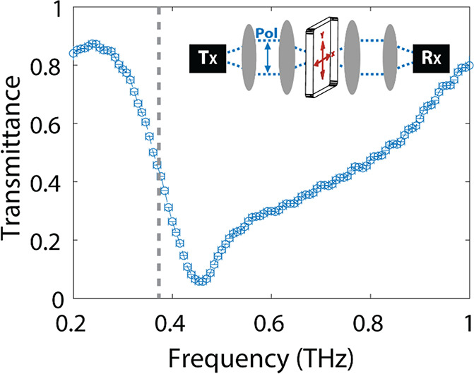
Measured far-field transmittance spectrum under normal incidence using a THz-TDS, as schematically depicted in the inset. The expected frequency of the BIC, as obtained from the CEMD model, is indicated by the gray dashed line. The spectral resolution of the measurements is 7 GHz.
We also performed angle-dependent transmittance measurements (see the Supporting Information, Figure S1). However, the extremely narrow resonance predicted by the CEMD calculations cannot be resolved in these measurements, as the frequency resolution of the THz time-domain spectrometer is 7 GHz, as can be seen in the measurement of Figure 3 and limited by reflections in the sample substrate, while the expected resonance line width is in the megahertz (MHz) range.
THz Near-Field Measurements of BICs
The complete suppression of the in- or out-coupling of electromagnetic radiation from the far-field makes the observation of BICs only possible with near-field techniques.45 As we show next, the field distribution associated with the symmetry-protected BICs can be directly imaged by the local excitation of one of the scatterers in a unit cell of the array and the near-field detection of the THz field on the surface of the 2D array. This local excitation and detection of ultrashort THz pulses is realized by using two separate microstructured photoconductive antennas, as depicted in Figure 4a. The operating principle of this setup is similar to that of a conventional THz-TDS system. A 100 fs optical pulse from a laser (λ = 780 nm) generates a single-cycle THz pulse in a microstructured photoconductive antenna (emitter) Tx with a certain dipole orientation depicted by the gray arrow in Figure 4a. This THz pulse can be detected with a second microstructured photoconductive antenna (receiver) Rx, which is gated with another optical pulse that has passed through a computer-controlled optical delay line. THz pulses can be detected on ultrashort time scales by varying the arrival time of the second pulse, obtaining both amplitude and phase information. By scanning Tx or Rx, these transient signals can be mapped in space, imaging the ultrafast THz field at arbitrary positions on the surface of the array. The small size of the emitter (the gap of the photoconductive switch is 5 μm) makes it possible to approximate it as a dipole emitter. This approximation is justified with measurements of the radiated THz field by the emitter and its propagation in free space that can be found in the Supporting Information (Figure S2).
Figure 4.

(a) Schematic representation of the THz near-field microscope used for the excitation and detection of BICs. (b) Normalized THz-field amplitudes as a function of time, plotted at increasing distances from Tx, which is located at −60 μm as graphically depicted by the black arrows on the lowest scatterer. Long-lasting oscillations of the electric field and a phase change of 180° between scatterers in a dimer are visible. This out-of-phase behavior is highlighted in (c) by plotting the field amplitudes at two neighboring scatterers marked by the green and purple dashed lines in (b).
The local excitation and near-field detection of the THz field amplitude is done without introducing a significant perturbation to the modes of the sample due to small dimensions of the photoconductive antennas.46 Therefore, this technique offers a unique opportunity for the investigation of the excitation and THz-field distribution in resonant structures and metasurfaces. A movie of the THz field amplitude on the 2D periodic lattice of gold scatterers can be found in the Supporting Information (Movie Figure 6.avi). For this measurement, as well as for the results discussed in the manuscript, the THz emitter was positioned in the middle of a gold scatterer situated in the center of the array and at a height of 3 μm above the scatterer. The measurements started 100 μm away to avoid unwanted laser reflections from Tx that could damage Rx, as these photoconductive antennas are inherently fragile.
The spatial extent of the field in the direction perpendicular to the long axis of the scatterers illustrates the formation of the BIC, as shown in Figure 4b. In this figure, the field emitted by Tx locally couples into the BIC on the scatterer, where the emitter is positioned. The out-of-plane field component (Ez) associated with this BIC is then measured as Rx is moved away from Tx. The lateral distance to the emitter increases successively from bottom to top as also graphically indicated by the scatterers on the left side of Figure 4b. In these measurements, we can see the time evolution of the pulse over the surface, showing pronounced oscillations of the near-field close to the scatterers. These long-lived oscillations can be associated with the symmetry-protected BIC on the surface of the array. As discussed above, this BIC emerges from the resonant response of the individual scatterers, which are antisymmetrically coupled with each other through an SLR in the array. Therefore, it is not surprising that the near-field amplitudes are at a maximum at the positions of the scatterers. The out-of-phase oscillation of adjacent scatterers in the unit cell of the array is visible in the near-field measurement. This out-of-phase oscillation is highlighted in Figure 4c, where the field amplitudes measured in the two scatterers of a dimer, indicated in Figure 4b with the dashed lines, are plotted as a function of time. We note that the near-field oscillation decays as the EM energy spreads over the full surface of the sample and is not due to radiation losses. The unavoidable finite size of the array will finally lead to a radiation leakage at the edges.
Figure 5 displays the spectra obtained by a Fourier transformation of the THz transients measured at different positions in Figure 4b. These spectra show a narrow peak at 0.39 THz, in excellent agreement with the expected frequency of the BIC obtained from the CEMD calculation (Figure 2). The line shape of the BIC, shown at the bottom of Figure 5 for two positions at scatterers in the same unit cell, is slightly asymmetric. This asymmetry can be explained with the calculated dispersion displayed in Figure 2: The tail in the spectrum of the BIC at lower frequencies stems from the fact that the associated resonance is excited at nonzero in-plane wave vectors that are accessible for the dipole source and to the non-negligible radiation leakage at these frequencies. In contrast, the near-field intensity peak decays abruptly at higher frequencies due to the absence of a resonance at those frequencies (see the dispersion plot in Figure 2). Note also that, as shown in the bottom plot of Figure 5, the spectra measured in adjacent scatterers have the same resonant frequency and similar amplitude, differing only in the phase.
Figure 5.

Normalized field intensity as a function of frequency at increasing distances from a dipole source located at −60 μm, as graphically depicted by the black arrows on the lowest scatterer on the left. The measured peak frequency agrees with the theoretically predicted BIC at 0.38 THz, as can be better observed from the cross cuts at the positions of the two scatterers in a dimer shown in the bottom figure.
A map of the field-profile distribution of the BIC can be obtained by a recording of the THz transients along a raster scan, a Fourier transformation of the transients, and a plot of the THz amplitude at the frequency of the BIC. The results of these measurements and analysis are shown in Figure 6a. This isofrequency amplitude map was made by measuring 80 ps long transients at spatial intervals of 15 μm, which are Fourier transformed and normalized to the global maximum to obtain the normalized field amplitude. Figure 6a shows the imaginary component of Ez at 0.39 THz extending over the array, with the measurements on the left panel and the CEMD calculations on the right panel.47 Note that the calculations were done without any adjustable parameter. Despite some artifacts in the measurements around the x = 0 line, resulting from the laser beam intensity scattered on the emitter and reaching the detector, the calculations nicely reproduce the experimental BIC local field. Both theory and experiment show the phase shift across successive scatterers in the same unit cell, beating out-of-phase from each other. This field amplitude distribution corroborates the argument that a pair of parallel out-of-phase resonant dipoles per unit cell are responsible for the symmetry protection of the BIC.15 An isofrequency amplitude map measurement at a slightly different frequency (0.42 THz) is shown in the Supporting Information (Figure S3). As appreciated in this measurement, the localized emission behavior of the dipole is recovered at other frequencies than the BIC frequency, where the radiation losses are significant and the extension of the field into the array is significantly less compared to the BIC.
Figure 6.

Normalized Im(Ez) electric field amplitude map over several unit cells of the array. (a) Measurement of the BIC at 0.39 THz and (b) CEMD calculation at 0.381 THz. Both data sets were normalized to their respective maximum field amplitudes. The excitation dipole is located at [X,Y] = [0 μm, −70 μm]. The gold scatterers are highlighted by the transparent gray areas.
Currently, the research on symmetry-protected BICs has mainly focused on dielectric structures that rely on the mirror and in-plane rotation symmetry protection to stabilize the BIC. These systems have been investigated by breaking the symmetry to form quasi-BICs that can be coupled to the continuum.12 However, the mirror symmetry can be relaxed to only include π-rotation symmetry, which in the case of single in-plane dipolar particles (e.g., metallic scatterers) will lead to an exceptional robustness of the BIC to relative displacements of the scatterers in the dimer. We tested this remarkable property on an array of dimer scatterers in which the scatterers are displaced by 30 μm in the x-direction, as shown in the measurements of Figure 7a, the CEMD calculations of (b), and in the movie of the THz field amplitude on the 2D lattice that can be found in the Supporting Information (Movie Figure 7.avi). The mirror symmetry of the dimer is broken in this sample, but the in-plane π-rotation symmetry is preserved. Both experimental and theoretical near-field maps shown in Figure 7 exhibit an intricate combination of amplitudes that maintain the out-of-phase condition of each (dipole) scatterer within the unit cell throughout the metasurface. We also measured the transmittance through this sample (Figure S5 in the Supporting Information), where only the broad super-radiant mode (Λ+) is observed, fully supporting the robustness of the BIC symmetry-protection mechanism.48
Figure 7.

Normalized Im(Ez) electric field amplitude plotted at 0.39 THz over several unit cells, with the measurement of the BIC shown on (a) and a calculation at 0.381 THz based on the CEMD theory, shown in (b). Both data sets were normalized to their respective maximum field amplitudes. The excitation dipole is located at [X,Y] = [0 μm, −70 μm]. The location of the gold particles is highlighted by the transparent gray areas.
Conclusion
With a double THz near-field technique that allows the local excitation and near-field detection of broadband THz pulses, we have been able to map for the first time the electromagnetic field of symmetry-protected BICs over extended areas. This investigation has been done in a periodic array of dimer scatterers supporting surface lattice resonances with a superradiant and a subradiant character. The near-field mapping of the BICs, associated with the subradiant mode, allows an unveiling of the field-symmetry protection that suppresses the far-field radiation. This suppression of the radiation leakage leads to modes with exceptionally long (diverging) life times and high Q-factors that cannot be detected in the far-field. By displacing the scatterers, we demonstrate experimentally that a mirror symmetry is not necessary for the formation of BICs and that only π-rotation symmetry is required. This property, confirmed by theoretical calculations based on a coupled electric-magnetic dipole theory in the frequency domain, makes symmetry-protected BICs exceptionally robust to relative displacements of the scatterers, which makes the fabrication of open resonant cavities with arbitrarily high Q-factors deemed simple. Although this investigation has been done at THz frequencies, it can be extended to other frequencies by scaling the dimensions and using nonabsorbing materials.
Acknowledgments
The authors thank K. de Mare for help in the development of the setup and Nederlandse Organisatie voor Wetenschappelijk Onderzoek (NWO) (Vici 680-47-628); Spanish Ministerio de Ciencia e Innovación (MICIU/AEI/FEDER, UE) through the grants MELODIA (PGC2018-095777–B-C21) and NANOTOPO (FIS2017-91413-EXP), and Ministerio de Educación, Cultura y Deporte through a PhD Fellowship (FPU15/03566) for funding.
Supporting Information Available
The Supporting Information is available free of charge at https://pubs.acs.org/doi/10.1021/acsphotonics.1c00937.
Sample fabrication. Coupled electric and magnetic dipole model. Angle-dependent transmission. Near-field maps of THz pulse propagation in free space. Isofrequency map away from BIC. Surface lattice resonances versus BICs. Robustness of the BICs to displacement (PDF)
Movie of measurements, Figure 6 (AVI)
Movie of measurements, Figure 7 (AVI)
Movie of measurements, Figure SI.1(a) (AVI)
Movie of measurements, Figure SI.1(c) (AVI)
The authors declare no competing financial interest.
Supplementary Material
References
- Weimann S.; Xu Y.; Keil R.; Miroshnichenko A. E.; Tünnermann A.; Nolte S.; Sukhorukov A. A.; Szameit A.; Kivshar Y. S. Compact surface fano states embedded in the continuum of waveguide arrays. Phys. Rev. Lett. 2013, 111, 240403. 10.1103/PhysRevLett.111.240403. [DOI] [PubMed] [Google Scholar]
- Kodigala A.; Lepetit T.; Gu Q.; Bahari B.; Fainman Y.; Kanté B. Lasing action from photonic bound states in continuum. Nature 2017, 541, 196–199. 10.1038/nature20799. [DOI] [PubMed] [Google Scholar]
- Doeleman H. M.; Monticone F.; Den Hollander W.; Alù A.; Koenderink A. F. Experimental observation of a polarization vortex at an optical bound state in the continuum. Nat. Photonics 2018, 12, 397–401. 10.1038/s41566-018-0177-5. [DOI] [Google Scholar]
- Koshelev K. L.; Sychev S. K.; Sadrieva Z. F.; Bogdanov A. A.; Iorsh I. V. Strong coupling between excitons in transition metal dichalcogenides and optical bound states in the continuum. Phys. Rev. B: Condens. Matter Mater. Phys. 2018, 98, 161113. 10.1103/PhysRevB.98.161113. [DOI] [Google Scholar]
- Romano S.; Zito G.; Torino S.; Calafiore G.; Penzo E.; Coppola G.; Cabrini S.; Rendina I.; Mocella V. Label-free sensing of ultralow-weight molecules with all-dielectric metasurfaces supporting bound states in the continuum. Photonics Res. 2018, 6, 726–733. 10.1364/PRJ.6.000726. [DOI] [Google Scholar]
- Contractor R.; Bahari B.; Vallini F.; Lepetit T.; Tellez-Limon R.; Park J. H.; Kodigala A.; Fainman Y.; Kante B. Integrable and steerable vortex lasers using bound states in the continuum. Frontiers in Optics 2019, JTu3A113. 10.1364/FIO.2019.JTu3A.113. [DOI] [Google Scholar]
- Marinica D. C.; Borisov A. G.; Shabanov S. V. Bound states in the continuum in photonics. Phys. Rev. Lett. 2008, 100, 183902. 10.1103/PhysRevLett.100.183902. [DOI] [PubMed] [Google Scholar]
- Hsu C. W.; Zhen B.; Lee J.; Chua S. L.; Johnson S. G.; Joannopoulos J. D.; Soljačić M. Observation of trapped light within the radiation continuum. Nature 2013, 499, 188–191. 10.1038/nature12289. [DOI] [PubMed] [Google Scholar]
- Blanchard C.; Hugonin J. P.; Sauvan C. Fano resonances in photonic crystal slabs near optical bound states in the continuum. Phys. Rev. B: Condens. Matter Mater. Phys. 2016, 94, 155303. 10.1103/PhysRevB.94.155303. [DOI] [Google Scholar]
- Hsu C. W.; Zhen B.; Stone A. D.; Joannopoulos J. D.; Soljacic M. Bound states in the continuum. Nature Reviews Materials 2016, 1, 1–13. 10.1038/natrevmats.2016.48. [DOI] [Google Scholar]
- Kodigala A.; Lepetit T.; Gu Q.; Bahari B.; Fainman Y.; Kanté B. Lasing action from photonic bound states in continuum. Nature 2017, 541, 196–199. 10.1038/nature20799. [DOI] [PubMed] [Google Scholar]
- Koshelev K.; Lepeshov S.; Liu M.; Bogdanov A.; Kivshar Y. Asymmetric Metasurfaces with High- Q Resonances Governed by Bound States in the Continuum. Phys. Rev. Lett. 2018, 121, 193903. 10.1103/PhysRevLett.121.193903. [DOI] [PubMed] [Google Scholar]
- Ha S. T.; Fu Y. H.; Emani N. K.; Pan Z.; Bakker R. M.; Paniagua-Domínguez R.; Kuznetsov A. I. Directional lasing in resonant semiconductor nanoantenna arrays. Nat. Nanotechnol. 2018, 13, 1042–1047. 10.1038/s41565-018-0245-5. [DOI] [PubMed] [Google Scholar]
- Carletti L.; Koshelev K.; De Angelis C.; Kivshar Y. Giant Nonlinear Response at the Nanoscale Driven by Bound States in the Continuum. Phys. Rev. Lett. 2018, 121, 033903. 10.1103/PhysRevLett.121.033903. [DOI] [PubMed] [Google Scholar]
- Abujetas D. R.; van Hoof N.; ter Huurne S.; Gómez Rivas J.; Sánchez-Gil J. A. Spectral and temporal evidence of robust photonic bound states in the continuum on terahertz metasurfaces. Optica 2019, 6, 996. 10.1364/OPTICA.6.000996. [DOI] [Google Scholar]
- Zito G.; Romano S.; Cabrini S.; Calafiore G.; De Luca A. C.; Penzo E.; Mocella V. Observation of spin-polarized directive coupling of light at bound states in the continuum. Optica 2019, 6, 1305. 10.1364/OPTICA.6.001305. [DOI] [Google Scholar]
- Han S.; Cong L.; Srivastava Y. K.; Qiang B.; Rybin M. V.; Kumar A.; Jain R.; Lim W. X.; Achanta V. G.; Prabhu S. S.; Wang Q. J.; Kivshar Y. S.; Singh R. All-Dielectric Active Terahertz Photonics Driven by Bound States in the Continuum. Adv. Mater. 2019, 31, 1901921. 10.1002/adma.201901921. [DOI] [PubMed] [Google Scholar]
- Wu M.; Ha S. T.; Shendre S.; Durmusoglu E. G.; Koh W. K.; Abujetas D. R.; Sánchez-Gil J. A.; Paniagua-Domínguez R.; Demir H. V.; Kuznetsov A. I. Room-Temperature Lasing in Colloidal Nanoplatelets via Mie-Resonant Bound States in the Continuum. Nano Lett. 2020, 20, 6005–6011. 10.1021/acs.nanolett.0c01975. [DOI] [PubMed] [Google Scholar]
- Abujetas D. R.; Barreda A.; Moreno F.; Sáenz J. J.; Litman A.; Geffrin J. M.; Sánchez-Gil J. A. Brewster quasi bound states in the continuum in all-dielectric metasurfaces from single magnetic-dipole resonance meta-atoms. Sci. Rep. 2019, 9, 1–11. 10.1038/s41598-019-52223-4. [DOI] [PMC free article] [PubMed] [Google Scholar]
- Liu Z.; Xu Y.; Lin Y.; Xiang J.; Feng T.; Cao Q.; Li J.; Lan S.; Liu J. High- Q Quasibound States in the Continuum for Nonlinear Metasurfaces. Phys. Rev. Lett. 2019, 123, 253901. 10.1103/PhysRevLett.123.253901. [DOI] [PubMed] [Google Scholar]
- Kupriianov A. S.; Xu Y.; Sayanskiy A.; Dmitriev V.; Kivshar Y. S.; Tuz V. R. Metasurface Engineering through Bound States in the Continuum. Phys. Rev. Appl. 2019, 12, 014024. 10.1103/PhysRevApplied.12.014024. [DOI] [Google Scholar]
- Cong L.; Singh R. Symmetry-Protected Dual Bound States in the Continuum in Metamaterials. Adv. Opt. Mater. 2019, 7, 1900383. 10.1002/adom.201900383. [DOI] [Google Scholar]
- Tan T. C.; Plum E.; Singh R. Lattice-Enhanced Fano Resonances from Bound States in the Continuum Metasurfaces. Adv. Opt. Mater. 2020, 8, 1901572. 10.1002/adom.201901572. [DOI] [Google Scholar]
- Liang Y.; Koshelev K.; Zhang F.; Lin H.; Lin S.; Wu J.; Jia B.; Kivshar Y. Bound States in the Continuum in Anisotropic Plasmonic Metasurfaces. Nano Lett. 2020, 20, 6351–6356. 10.1021/acs.nanolett.0c01752. [DOI] [PubMed] [Google Scholar]
- Koshelev K.; Bogdanov A.; Kivshar Y. Meta-optics and bound states in the continuum. Science Bulletin 2019, 64, 836–842. 10.1016/j.scib.2018.12.003. [DOI] [PubMed] [Google Scholar]
- Zhao X.; Chen C.; Kaj K.; Hammock I.; Huang Y.; Averitt R.; Zhang X. Terahertz investigation of bound states in the continuum of metallic metasurfaces. Optica 2020, 7, 1548–1554. 10.1364/OPTICA.404754. [DOI] [Google Scholar]
- Paddon P.; Young J. F. Two-dimensional vector-coupled-mode theory for textured planar waveguides. Phys. Rev. B: Condens. Matter Mater. Phys. 2000, 61, 2090–2101. 10.1103/PhysRevB.61.2090. [DOI] [Google Scholar]
- Tikhodeev S. G.; Yablonskii A. L.; Muljarov E. A.; Gippius N. A.; Ishihara T. Quasiguided modes and optical properties of photonic crystal slabs. Phys. Rev. B: Condens. Matter Mater. Phys. 2002, 66, 045102. 10.1103/PhysRevB.66.045102. [DOI] [Google Scholar]
- Lee J.; Zhen B.; Chua S.-L.; Qiu W.; Joannopoulos J. D.; Soljačić M.; Shapira O. Observation and Differentiation of Unique High-Q Optical Resonances Near Zero Wave Vector in Macroscopic Photonic Crystal Slabs. Phys. Rev. Lett. 2012, 109, 067401. 10.1103/PhysRevLett.109.067401. [DOI] [PubMed] [Google Scholar]
- Yuan L.; Lu Y. Y. Perturbation theories for symmetry-protected bound states in the continuum on two-dimensional periodic structures. Phys. Rev. A: At., Mol., Opt. Phys. 2020, 101, 043827. 10.1103/PhysRevA.101.043827. [DOI] [Google Scholar]
- Monticone F.; Sounas D.; Krasnok A.; Alù A. Can a Nonradiating Mode Be Externally Excited? Nonscattering States versus Embedded Eigenstates. ACS Photonics 2019, 6, 3108–3114. 10.1021/acsphotonics.9b01104. [DOI] [Google Scholar]
- Taghizadeh A.; Chung I. S. Quasi bound states in the continuum with few unit cells of photonic crystal slab. Appl. Phys. Lett. 2017, 111, 031114. 10.1063/1.4990753. [DOI] [Google Scholar]
- Bulgakov E. N.; Maksimov D. N. Light enhancement by quasi-bound states in the continuum in dielectric arrays. Opt. Express 2017, 25, 14134. 10.1364/OE.25.014134. [DOI] [PubMed] [Google Scholar]
- Dong Z. D.; Mahfoud Z.; Paniagua-Domínguez R.; Wang H.; I F.-D. A.; Sergey G.; Tung Ha S.; Tjiptoharsono F.; Kuznetsov A. I.; Bosman M.; Yang J. K. W.. Photonic Bound-States-in-the-Continuum Observed with an Electron Nanoprobe. arXiv:2105.04220; 2021
- Bulgakov E. N.; Sadreev A. F. Bloch bound states in the radiation continuum in a periodic array of dielectric rods. Phys. Rev. A: At., Mol., Opt. Phys. 2014, 90, 53801. 10.1103/PhysRevA.90.053801. [DOI] [Google Scholar]
- Abujetas D. R.; Sánchez-Gil J. A.; Sáenz J. J. Generalized Brewster effect in high-refractive-index nanorod-based metasurfaces. Opt. Express 2018, 26, 31523. 10.1364/OE.26.031523. [DOI] [PubMed] [Google Scholar]
- Abujetas D. R.; Olmos-Trigo J.; Sáenz J. J.; Sánchez-Gil J. A. Coupled electric and magnetic dipole formulation for planar arrays of particles: Resonances and bound states in the continuum for all-dielectric metasurfaces. Phys. Rev. B: Condens. Matter Mater. Phys. 2020, 102, 125411. 10.1103/PhysRevB.102.125411. [DOI] [Google Scholar]
- Reid M. T.; Johnson S. G. Efficient Computation of Power, Force, and Torque in BEM Scattering Calculations. IEEE Trans. Antennas Propag. 2015, 63, 3588–3598. 10.1109/TAP.2015.2438393. [DOI] [Google Scholar]
- Reid M. T. H.SCUFF-EM documentation, 2021. Online at http://homerreid.github.io/scuff-em-documentation/.
- Wang W.; Ramezani M.; Väkeväinen A. I.; Törmä P.; Rivas J. G.; Odom T. W. The rich photonic world of plasmonic nanoparticle arrays. Mater. Today 2018, 21, 303–314. 10.1016/j.mattod.2017.09.002. [DOI] [Google Scholar]
- Kravets V. G.; Kabashin A. V.; Barnes W. L.; Grigorenko A. N. Plasmonic Surface Lattice Resonances: A Review of Properties and Applications. Chem. Rev. 2018, 118, 5912–5951. 10.1021/acs.chemrev.8b00243. [DOI] [PMC free article] [PubMed] [Google Scholar]
- Humphrey A. D.; Meinzer N.; Starkey T. A.; Barnes W. L. Surface Lattice Resonances in Plasmonic Arrays of Asymmetric Disc Dimers. ACS Photonics 2016, 3, 634–639. 10.1021/acsphotonics.5b00727. [DOI] [Google Scholar]
- Mitrofanov O.; Todorov Y.; Gacemi D.; Mottaghizadeh A.; Sirtori C.; Brener I.; Reno J. L. Near-field spectroscopy and tuning of sub-surface modes in plasmonic terahertz resonators. Opt. Express 2018, 26, 7437. 10.1364/OE.26.007437. [DOI] [PubMed] [Google Scholar]
- Van Hoof N. J.; Ter Huurne S. E.; Vervuurt R. H.; Bol A. A.; Halpin A.; Gómez Rivas J. Diffraction enhanced transparency in a hybrid gold-graphene THz metasurface. APL Photonics 2019, 4, 036104. 10.1063/1.5080390. [DOI] [Google Scholar]
- Sadrieva Z. F.; Belyakov M. A.; Balezin M. A.; Kapitanova P. V.; Nenasheva E. A.; Sadreev A. F.; Bogdanov A. A. Experimental observation of a symmetry-protected bound state in the continuum in a chain of dielectric disks. Phys. Rev. A: At., Mol., Opt. Phys. 2019, 99, 53804. 10.1103/PhysRevA.99.053804. [DOI] [Google Scholar]
- Bhattacharya A.; Gómez Rivas J. Full vectorial mapping of the complex electric near-fields of THz resonators. APL Photonics 2016, 1, 086103. 10.1063/1.4962905. [DOI] [Google Scholar]
- Abujetas D. R.; Sánchez-Gil J. A. Near-Field Excitation of Bound States in the Continuum in All-Dielectric Metasurfaces through a Coupled Electric/Magnetic Dipole Model. Nanomaterials 2021, 11, 998. 10.3390/nano11040998. [DOI] [PMC free article] [PubMed] [Google Scholar]
- Yuan L.; Lu Y. Y. Conditional robustness of propagating bound states in the continuum in structures with two-dimensional periodicity. Phys. Rev. A: At., Mol., Opt. Phys. 2021, 103, 043507. 10.1103/PhysRevA.103.043507. [DOI] [Google Scholar]
Associated Data
This section collects any data citations, data availability statements, or supplementary materials included in this article.
Data Citations
- Dong Z. D.; Mahfoud Z.; Paniagua-Domínguez R.; Wang H.; I F.-D. A.; Sergey G.; Tung Ha S.; Tjiptoharsono F.; Kuznetsov A. I.; Bosman M.; Yang J. K. W.. Photonic Bound-States-in-the-Continuum Observed with an Electron Nanoprobe. arXiv:2105.04220; 2021