

Abstract
Mechanical forces are known to affect the biomechanical properties of native and engineered cardiovascular tissue. In particular, shear stress that results from the relative motion of heart valve leaflets with respect to the blood flow is one important component of their mechanical environment in vivo. Although different types of bioreactors have been designed to subject cells to shear stress, devices to expose biological tissue are few. In an effort to address this issue, the aim of this study was to design an ex vivo tissue culture system to characterize the biological response of heart valve leaflets subjected to a well-defined steady or time-varying shear stress environment. The novel apparatus was designed based on a cone-and-plate viscometer. The device characteristics were defined to limit the secondary flow effects inherent to this particular geometry. The determination of the operating conditions producing the desired shear stress profile was streamlined using a computational fluid dynamic (CFD) model validated with laser Doppler velocimetry. The novel ex vivo tissue culture system was validated in terms of its capability to reproduce a desired cone rotation and to maintain sterile conditions. The CFD results demonstrated that a cone angle of 0.5 deg, a cone radius of 40 mm, and a gap of 0.2 mm between the cone apex and the plate could limit radial secondary flow effects. The novel cone-and-plate permits to expose nine tissue specimens to an identical shear stress waveform. The whole setup is capable of accommodating four cone-and-plate systems, thus concomitantly subjecting 36 tissue samples to desired shear stress condition. The innovative design enables the tissue specimens to be flush mounted in the plate in order to limit flow perturbations caused by the tissue thickness. The device is capable of producing shear stress rates of up to 650 dyn cm−2 s−1 (i.e., maximum shear stress rate experienced by the ventricular surface of an aortic valve leaflet) and was shown to maintain tissue under sterile conditions for 120 h. The novel ex vivo tissue culture system constitutes a valuable tool toward elucidating heart valve mechanobiology. Ultimately, this knowledge will permit the production of functional tissue engineered heart valves, and a better understanding of heart valve biology and disease progression.
Keywords: cone-and-plate, viscometer, bioreactor, shear stress, heart valve, tissue engineering, mechanotransduction
Introduction
Cardiovascular tissue is subjected to a complex combination of mechanical stimuli such as pressure, bending and tensile stretches, and flow. These forces potently regulate the biology and patho-physiology of cardiovascular tissue and cells [1–10], and affect the development of tissue engineered cardiovascular constructs [11,12]. In particular, the mechanisms ensuring the proper function of heart valves are essentially controlled by the surrounding hemodynamic environment. Therefore, understanding the interactions between heart valves and their fluid dynamic environment is critical to better understand normal valve function and disease progression. Although devices are available to subject heart valves to pressure, stretch, or a combination of pressure, flow, and stretch, systems subjecting tissue to shear stress are few and those that exist only crudely mimic the in vivo environment [5,13–15].
The parallel plate apparatus is one such device that has been designed to better understand the effects of shear stress on cell cultures in vitro. The system consists of two stationary parallel plates [16]. Fluid flows between the inlet and outlet sections under a pressure differential. When used for cell culture, the device is generally operated to produce a fully developed laminar flow. The magnitude of the pressure differential and the dimensions of the channel cross section control the wall-shear stress distribution on the surface of the plates. Parallel plate systems are limited to the production of steady uniform shear stress due to the inertia of their driving components (e.g., pumps) and that of the large volume of working fluid. Several modifications have been made in recent years to accommodate oscillatory shear stress and disturbed complex flow conditions [16–21].
The cone-and-plate apparatus is another device capable of producing a nearly uniform shear stress in the culture environment. Initially used for the viscosity measurement of fluids [22], this device consists of an inverted cone rotating above a flat stationary plate. Fluid flows within the gap between the cone and the plate. The control of the shear stress distribution on the plate surface is dependent on the angular velocity imposed on the cone rotation. The cone-and-plate apparatus offers several advantages over the parallel plate device. Its particular geometry permits the production of wider ranges of flow regimes and shear stresses while requiring a lesser volume of fluid. Those reasons make this apparatus the device of choice to subject cells to pulsatile or oscillatory shear stresses characterized by large shear stress rates. The flow produced in this device has been extensively investigated experimentally, analytically, and computationally [23–26].
As a first approximation, the flow produced in the device can be solved by neglecting inertial effects. Under this assumption, the primary flow is essentially tangential and the shear stress distribution on the plate surface is theoretically uniform [22]. Although this simplification has been largely adopted for the initial development of cone-and-plate viscometers, its validity was examined in several investigations. Fewell and Hellums [27] numerically demonstrated that the particular geometry of the cone-and-plate apparatus could produce a secondary flow. Pelech and Shapiro [28] identified the ratio of centrifugal forces to viscous forces as the main parameter governing the onset of the secondary flow effects. This ratio also known as the Reynolds number was defined as
| (1) |
where Rc is the cone radius, α is the angle between the plate and the cone, ω is the angular velocity of the cone, and ν is the kinematic viscosity of the working fluid. Sdougos et al. [29] carried out flow visualization and measurements to demonstrate the dependence of the flow regime upon the Reynolds number. At Re<1, the flow produced in the cone-and-plate device is essentially axisymmetric, laminar, and tangential. At 1⩽Re⩽4, secondary flow effects intensify and the laminar flow becomes three dimensional. Finally, at Re>4, the flow is fully turbulent.
When used in biomedical applications, the regime of interest generally corresponds to laminar three-dimensional flow and the rotation imposed on the cone is usually unsteady and periodic. Buschmann et al. [30] carried out a computational assessment of both oscillating and pulsatile flows in a practical cone-and-plate geometry. Their study showed that the presence of a secondary flow affects the uniformity of the shear stress distribution on the plate. More recently, Chung et al. [31] used an analytical perturbation method to derive the contributions of both the primary and secondary flows on the shear stress distribution on the plate surface. Those effects were described for an unsteady oscillatory rotation of the cone that was found to affect the uniformity of the shear stress distribution on the plate surface. The primary flow produces a primary stress oriented in the tangential direction, whereas the secondary flow induced by the centrifugal force produces a secondary stress oriented in the radial direction.
Many cone-and-plate designs have been investigated, each providing a better control over the production of a uniform shear stress environment. Bussolari et al. [32] designed a cone-and-plate apparatus for use in exposing cells to shear stresses ranging from 10−2 to 102 dyn cm−2. The system was shown to maintain the cells in healthy condition for periods of up to 14 days. More recently, Blackman et al. [33,34] developed a cone-and-plate bioreactor allowing for the precise control of the biomechanical culture environment. The device was used to expose cells cultured on the surface of the plate to unsteady shear stress waveforms. The angular velocity of the cone could be adjusted via the use of a microstepper motor, and the distance between the cone apex and the plate could be precisely set via a pair of micrometers.
Although those designs certainly improve the control over the hydrodynamic environment, their use is limited to the culture of cell monolayers characterized by a uniform thickness throughout the plate surface. Cell cultures permit to precisely control the environment of isolated cells and constitute simplified models to study cellular biology in a particular context. However, they are not sufficient to account for cell-cell and cell-extracellular matrix interactions among various cell types. For example, arteries contain not only endothelial cells lining the vessel lumen but also medial smooth muscle cells and adventitial layer with fibroblasts. Heart valves also contain endothelial lining and valvular interstitial cells in the ventricularis, spongiosa, and fibrosa. Therefore, it is essential to study how the intact tissues respond to well-defined and in situ-like hemodynamic conditions. It was the goal of this study to develop a shear device that can expose heart valve leaflets to defined in vivo-like shear stress conditions in order to study mechanoresponses of the valve ex vivo.
The implementation of a cone-and-plate apparatus to subject tissue to a controlled shear stress environment is challenging because of the finite thickness of the tissue that is expected to cause some perturbations to the surrounding flow and thus to affect the uniformity of the wall-shear stress. Therefore, the present paper describes the design of a novel ex vivo tissue culture system capable of exposing whole pieces of biological tissue to a specific unsteady and spatially uniform shear stress environment. This novel design can accommodate circular tissue samples flush mounted in the bottom plate to avoid any perturbation to the surrounding flow. The choice of an ex vivo system over traditional in vitro and in vivo systems is justified by the requirements of maintaining the cells in their native extracellular matrix and accurately controlling their mechanical environment. The proposed device will help determine the relationships between shear stress and the biological properties of native tissues. The design of the novel tissue culture system will be developed according to the following steps. A geometry complying with the requirement to limit secondary flow effects will be chosen as a starting point. The determination of suitable operating conditions will be streamlined via the use of a computational fluid dynamics (CFD) model. The validity of the model will be experimentally assessed using laser Doppler velocimetry (LDV). Finally, the apparatus will be tested in terms of its capability to maintain sterility and produce the desired mechanical environment.
Materials and Methods
Geometrical and Mechanical Requirements.
As suggested by the studies described above, under certain conditions (i.e., low Reynolds number, no gap between the cone apex and the bottom plate, infinite cone-plate system, and small angle between the cone and the plate), the cone-and-plate device produces a primary flow mainly oriented along the azimuthal direction and a uniform wall-shear stress on the surface of the bottom plate defined as
| (2) |
where ρ is the density of the working fluid. Although most of those conditions can be practically met, the actual bioreactor has finite dimensions, and the presence of end effects near the cone outer wall and the cone apex generates a secondary flow, making the flow three dimensional and shrinking the domain of uniform shear stress on the plate surface [31]. However, although cell culture applications generally require the unsteady rotation of the cone that alters the uniformity of the shear stress [31], this formulation of the shear stress distribution on the plate surface is usually considered when the cone-and-plate apparatus is used as a biomedical device. More importantly, in the presence of a significant gap h between the cone apex and the bottom plate, the wall-shear stress measured on the plate surface becomes spatially dependent and can be modeled as
| (3) |
where r is the radial coordinate.
Therefore, with the knowledge of a particular shear stress waveform and a particular cone-and-plate geometry, Eq. (3) can then be used to determine the corresponding cone angular velocity waveform. The chosen geometry is based on the device used by Sorescu et al. [35] to condition cells to oscillatory shear stress. It consists of a cone angle of 0.5 deg, a cone radius of 40 mm, and a gap of 0.2 mm between the cone apex and the plate (Fig. 1). Those dimensions comply with the geometrical requirements cited earlier to allow for the production of a flow mainly oriented in the tangential direction and to neglect secondary flow effects. Since the novel tissue culture system will be primarily used to expose aortic valve leaflets to different shear stress conditions, the device was dimensioned to allow for the production of physiologic shear stresses experienced by the ventricular surface of the leaflet. This particular shear stress waveform was obtained using a CFD model of the flow through a trileaflet heart valve with prescribed kinematics resulting from a separate structural deformation calculation. As shown in Fig. 2(a), the physiologic shear stress waveform has a period of 0.86 s (i.e., heart rate of 70 beats/min) and is approximately half a sine wave varying from 0 dyn cm−2 to 79.0 dyn cm−2 followed by a constant zero shear stress. The tissue samples were assumed to be equiangularly positioned at a radius r=20 mm from the center of the device. The viscosity of the working fluid (Dulbecco’s Modified Eagle’s Medium—high glucose, Sigma-Aldrich Co., St Louis, MO) was measured at 37°C (i.e., temperature of the working fluid inside the incubator). The measurements yielded a kinematic viscosity of 0.95±0.01 cSt. Equation (3) was then used as an aid in determining the corresponding cone angular velocity. As shown in Fig. 2(b), the initial waveform is characterized by a maximum velocity of 1489 rpm. At that angular velocity, the Reynolds number is 1.66 and corresponds to a three-dimensional laminar flow regime for which secondary flow effects may be significant.
Fig. 1.
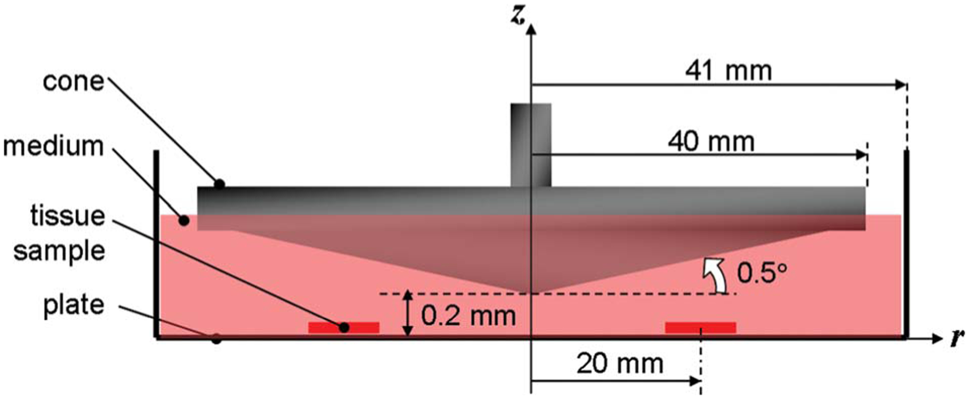
Typical cone-and-plate system complying with the dimensional requirements to limit secondary flow effects. The cone located 0.2 mm above the flat stationary plate has an angle of 0.5 deg and a radius of 40 mm. The gap between the cone and the plate is filled with fluid.
Fig. 2.
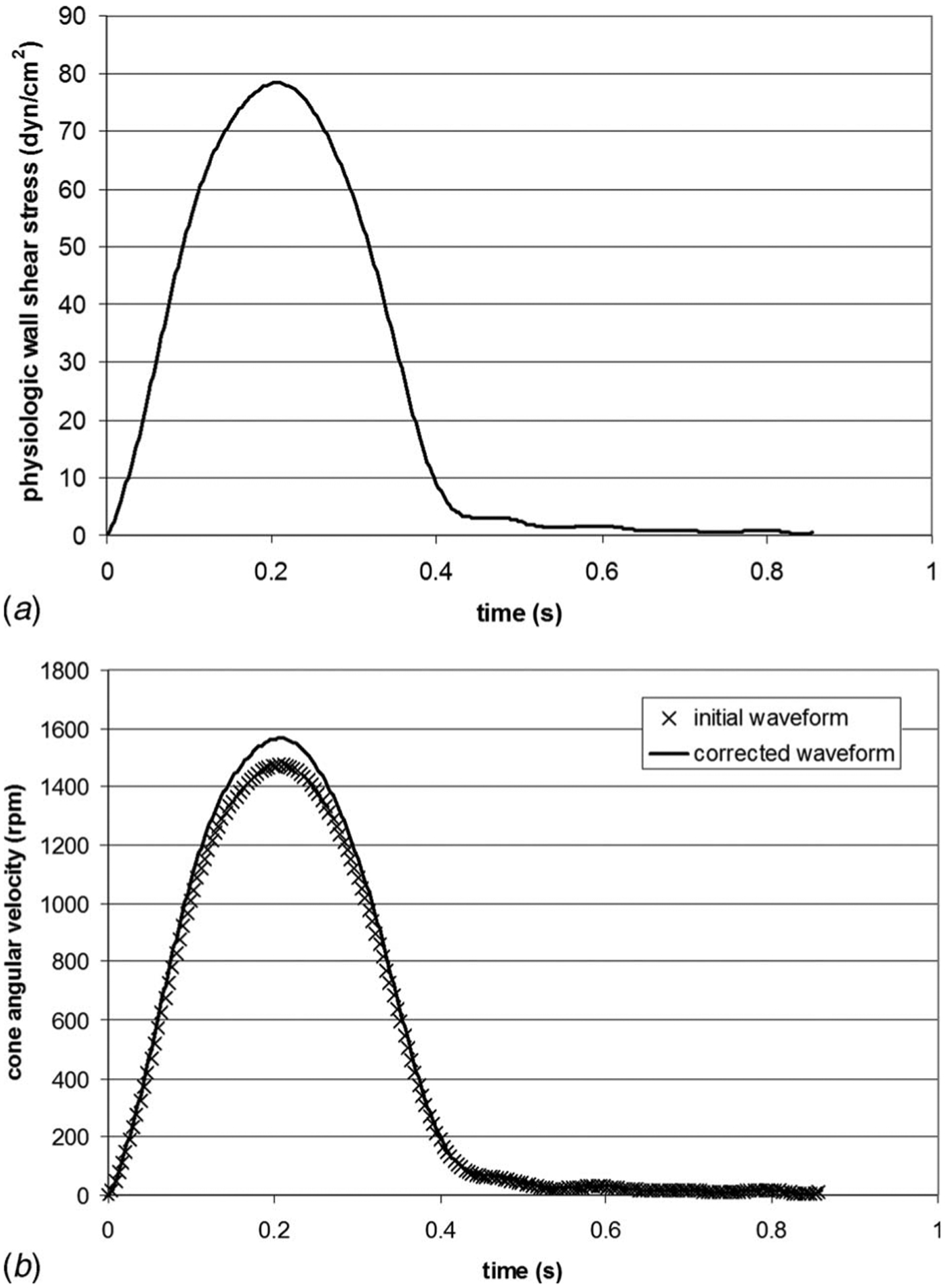
(a) Physiologic wall-shear stress waveform experienced by the ventricular surface of aortic valve leaflets over one cardiac cycle and (b) comparison between the initial and corrected cone velocity waveforms used to produce the physiologic ventricular shear stress variations
Computational Fluid Dynamic Model.
The cone angular velocity ω calculated from Eq. (3) does not account for secondary flow effects. In order to test the validity of this assumption in the geometry described above, a CFD model was designed. Although the problem could have been treated using a two-dimensional approach, a three-dimensional geometry was preferred to permit future modifications that would make the geometry non-axisymmetric. Therefore, a 40 deg slice of the geometry was constructed using gambit, a commercial mesh generator. The inlet and outlet sections of the slice were assigned a periodic boundary condition. A condition of zero shear was imposed on the free surface. Finally, the cone surface was modeled as a wall rotating at the unsteady velocity waveform calculated earlier. The fluid volume was meshed using a Cartesian grid consisting of 260,000 tetrahedral elements. The unsteady three-dimensional Navier–Stokes equations were then solved using fluent (Fluent Inc., Lebanon, NH), a commercial CFD software package. The segregated numerical scheme that sequentially integrates the continuity and momentum equations was preferred to the coupled scheme because of its better performance with incompressible flows. One period (T=0.86 s) was divided into 50 time steps (Δt=17.2 ms). The computations were initialized with the cone at rest and were run for five periods (i.e., 250 time steps).
Laser Doppler Velocimetry Measurements.
The validity of the CFD model was experimentally investigated using two-component LDV. A prototype cone-and-plate device with the same dimensions as those used in the CFD study was fabricated for these experiments.
Laser Doppler Velocimetry System.
Two-component LDV measurements were obtained with a three-component fiber-optic LDV system (Aerometrics Inc, Sunnyvale, CA) used in coincident backscattering mode. A 5 W multiline argon-ion laser (Innova 70, Coherent, Santa Clara, CA) was coupled to a fiber drive unit to allow color separation of the incoming primary beam. The resulting green (514.5 nm wavelength) and blue (488 nm wavelength) beams were used for the two-component measurements. A Bragg cell was used to add a 40 MHz frequency shift to one beam of each color pair. A two-component receiver (Model XRV 1204, TSI Inc., Shoreview, MN) with a 100 mm focal length lens was coupled to the fiber-optic couplers to produce an ellipsoidal measurement volume with minor and major axes of approximately 21 μm and 140 μm, respectively.
Experimental Setup.
The cone-and-plate system was clamped at the ends of the bottom plate and mounted on a rigid aluminum frame attached to a base fixed to a leveled optical table. The two-component LDV transmitter/receiver was mounted on a micrometer-controlled transverse system and was positioned below the cone-and-plate system such that its optical face was parallel to the clear surface of the plate. The two laser beams emitting from the transmitter/receiver intersected in the fluid gap and illuminated an ellipsoidal volume of fluid. In order to compensate for the distortion due to the refraction of light at wall-fluid interfaces, the prototype was made of acrylic, and an index-matching solution of sodium iodide, glycerin, and water was employed as the working fluid (n=1.49; ν =3.39 mm2 s−1). The fluid was seeded with silicon carbide particles (1.5 μm diameter) to acquire a good Doppler burst signal.
Measurement Description.
The tangential velocity component was obtained at r=20 mm, r=30 mm, and r=36 mm, at a constant cone angular velocity of 200 rpm. The measurements at each radius were obtained from the nearest measurable point to the inner surface of the bottom plate to the nearest measurable point to the inner surface of the cone, in a 25 μm increment (see inset of Fig. 5). The Doppler signals were processed with fast Fourier transform based real-time signal analyzers (Aerometrics, Model RSA1000L, TSI Inc, Shoreview, MN), and a commercial software package (Aerometrics System Software, Particle Acquisition and Analysis, Version 0.80) was used to acquire data and control both the signal analyzers and the photomultiplier hardware.
Fig. 5.
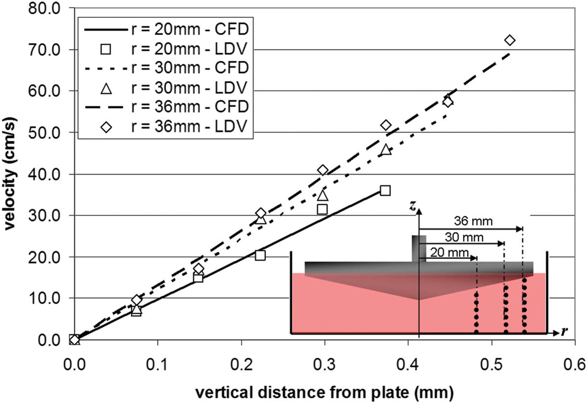
Point-to-point comparison of the tangential velocity measured by LDV and predicted by CFD at three sets of points (r=20 mm, r=30 mm, and r=36 mm, respectively) aligned along the vertical direction, under a steady rotation of the cone (ω =200 rpm)
Design Solution
Cone-and-Plate Assembly.
The novel cone-and-plate apparatus was designed using solid edge cad software (UGS, Plano, TX). The geometrical features of the system are similar to those described in the CFD and LDV studies. Although the dimensions of this geometry have been computationally validated, the real challenge of the this new apparatus is to expose whole pieces of tissue to a homogeneous shear stress. As compared to cell monolayers, tissue has a finite thickness, which may cause some perturbations to the surrounding flow and dramatically affect the uniformity of the shear stress produced over its surface. This issue has been solved in the design solution described below.
The device (Fig. 3(a)) consists of a cylindrical plate (82 mm inner diameter, 19 mm deep) made of polycarbonate and containing nine equiangularly spaced cylindrical wells (7 mm diameter, 6.35 mm deep) located at a radius r=20 mm from the center of the plate. Situated within each well is a cylindrical stainless-steel holder featuring a chamfer (45 deg angle) on the top surface. Three different sets of holders can be used in the device, each with a different height (9.01 mm, 8.91 mm, and 8.81 mm) in order to accommodate tissue samples of different thicknesses (0.50 mm, 0.60 mm, and 0.70 mm, respectively). The respective dimensions of each of the three sets have been chosen to cover the typical range of aortic valve leaflet thicknesses. If the device were to be used with a different tissue, new holders could be fabricated. The device can thus accommodate a total of nine tissue samples lying on the top surface of the nine holders. A cylindrical plate cover made of polycarbonate (82 mm diameter, 3.2 mm high) is positioned on the top surface of the cylindrical plate and is maintained by six equiangularly spaced screws located at a radius r=37 mm from the center of the device and flushed with the top surface of the plate cover. The plate cover features nine chamfered holes (45 deg chamfer angle) such that the diameter of the holes varies from 5 mm to 7 mm from the top surface of the plate cover to the bottom surface. The chamfered surfaces machined in the plate cover are in contact with the circular edge of the tissue samples, thus maintaining them in position on top of their holders and exposing a circular area (5 mm diameter) to the flow (Figs. 3(b) and 3(c)). Shear stress is produced by the rotation of the cone made of Delrin (80 mm diameter, 179 deg cone angle, 10.2 mm high). The cone is attached at the end of a shaft (9.5 mm top diameter, 38.1 mm bottom diameter, 54 mm high) made of stainless steel via three screws. The cylindrical flange (27 mm top outer diameter, 88.9 mm bottom outer diameter, 19 mm inner diameter, 28.6 mm high) sits on the top edge of the plate and closes the device. The flange contains a pair of ball bearings (ABEC-1 double sealed bearing No. R6, McMaster-Carr, Atlanta, GA) aligned along its vertical axis, allowing the top part of the shaft to rotate with minimum friction. Nine holes located around the perimeter of the flange ensure proper gas exchange by bringing air from the surroundings into the device. The axes of the holes machined on the perimeter of the flange are horizontal to prevent contamination. Finally, the distance of 0.2 mm between the cone apex and the plate cover is set by placing two No. 2 micro-cover-slides (Model 48368-062, VWR Scientific, Inc., West Chester, PA) on the top surface of the plate cover. The combined thickness of those slides (0.202±0.004 mm) was verified using a caliper. After being adjusted, the vertical distance is maintained by a cylindrical shaft collar made of stainless steel sitting on the top surface of the topmost ball bearing. The set screw located in the shaft collar and contacting a flat rectangular surface machined on the main shaft permits to fix the distance between the cone apex and the surface of the plate cover (i.e., surface of tissue samples) after adjusting the vertical position of the shaft. Once the screw is secured, the micro-cover-slides can be removed from the apparatus.
Fig. 3.
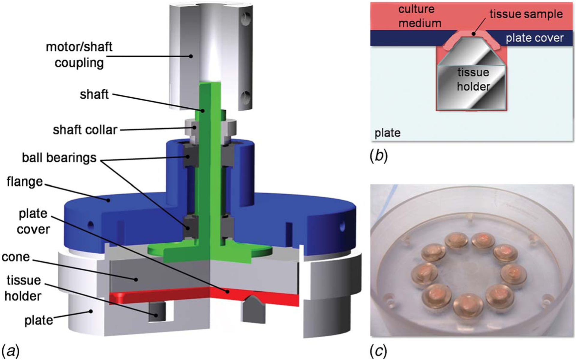
Design solution: (a) cross-sectional rendering of the cone-and-plate assembly showing the main components of the system; (b) schematic of the tissue mounting system; and (c) picture of the bottom plate, tissue holders, and plate cover with mounted tissue samples
Driving and Monitoring System.
A base has been designed to maintain the cone-and-plate assembly in position during motion. The base made of polycarbonate consists of two parallel square tables (300×300 mm2) distant from 100 mm. The top table features four holes for the positioning of servo motors. The bottom table features four concentric suction channels connected together via three rectangular channels (i.e., two transversal and one central), and covered by suction lids. The purpose of the concentric channels is to center the plate of the cone-and-plate assembly with respect to the servo motor and to maintain the assembly in position during motion. The central channel is connected to a suction port located on the front side of the bottom plate. Four polycarbonate rods are screwed in the corners of the bottom table to support the top table. The diameter of the rods (19 mm) is large enough to stabilize the entire assembly and damp the inherent vibrations produced by the servo motor. In an effort to maximize the efficiency of the device, the base can accommodate four servo motors as well as four cone-and-plate assemblies, thus simultaneously allowing the culture of 36 tissue samples.
The rotary servo motor (SM232AE-NPSN, Parker-Hannifin Corp., Cleveland, OH) is fixed to the top plate of the base via four screws and is coupled to the shaft of the cone-and-plate assembly via a coupling device (acetal helical beam coupling, McMaster-Carr, Atlanta, GA), allowing for both parallel and angular misalignments. The rotary servo motor chosen in the current setup was dimensioned to provide the necessary torque and velocity to produce shear stress variations that encompass the shear stress rates experienced by aortic valve leaflets in vivo. The motor is controlled by a single-axis servo drive/controller (Model GV6K Gemini GV-L3, Parker-Hannifin Corp., Cleveland, OH) connected to a computer (Inspiron 710m, Dell Inc., Round Rock, TX) via an RJ 45 connection. The controller/drive implemented in the present setup offers complex programming and I/O capabilities using the software package supplied with the product (Motion Planner, Parker-Hannifin Corp., Cleveland, OH). The production of a desired angular velocity waveform can be monitored in real time via a digital/analog acquisition card and box (DAQCard-6024E and BNC-2110, National Instruments Corp., Austin, TX) that converts the analog velocity output provided by the motor feedback into a digital signal that can be visualized on the computer using the software package labview 8.0 (National Instruments Corp., Austin, TX).
Sterility Assessment.
It was important to assess the ability of the bioreactor to maintain sterile conditions during tissue culture. In order to assess any change in cell structure and morphology that could be indicative of cell damage, aortic valve leaflets were cultured for 120 h in the bioreactor, embedded in optimal cutting medium (OCT; Electron Microscopy Sciences, Hatfield, PA) and cut into 5 μm sections. These sections were then stained with 0.25 μg ml−1 4′, 6-diamidino-2-phenylindole (DAPI; Sigma), coverslipped, and stored at 4°C. Slides were subsequently imaged using a DAPI filter under a mercury lamp.
Results
CFD.
The wall-shear stress variations on the plate surface were extracted at the center of the region where the tissue samples are situated (i.e., r=20 mm from the center of the device), after transient effects were considered negligible (i.e., after one period). The maximum wall-shear stress predicted by the CFD model at the center of the tissue sample was 74.4 dyn cm−2. This maximum is 6% lower than the value of 79.0 dyn cm−2 desired at the same location. This discrepancy demonstrates the presence of a secondary flow and the limits of the validity of Eq. (3). In an effort to compensate for those effects, the cone angular velocity was scaled to produce the desired maximum shear stress of 79.0 dyn cm−2. A linear relation was assumed between the increase in angular velocity and the increase in wall-shear stress. The corrected cone angular velocity shown in Fig. 2(b) attains a maximum of 1564 rpm, yielding a maximum Reynolds number of 1.74 that still characterizes a three-dimensional laminar flow regime. The corrected angular velocity waveform was then input as a boundary condition for the cone surface in the CFD model and the computations were restarted. The use of the corrected angular velocity did not affect the duration of the transient effects that were still considered negligible after one period. As shown in Fig. 4, the shear stress variations predicted by the CFD model at the center of the sample are in good agreement with the physiologic shear stress, both quantitatively and qualitatively. The close match between the computed and targeted shear stress waveforms validates the use of the corrected cone angular velocity waveform and demonstrates the nonvalidity of Eq. (3) at the current Reynolds number. Another point of interest was the assessment of the shear stress variations over the area occupied by the tissue sample (i.e., circle of 5 mm diameter centered at r=20 mm from the center of the device). At each time step, the surface-averaged wall-shear stress was computed and then compared to the shear stress predictions at the center of the sample. The results are shown in Fig. 4. The red markers represent the maximum and minimum shear stress values predicted by CFD over the sample area. The results demonstrate the capability of this particular cone-and-plate geometry to produce a homogeneous shear stress of desired magnitude over the area occupied by the tissue samples.
Fig. 4.
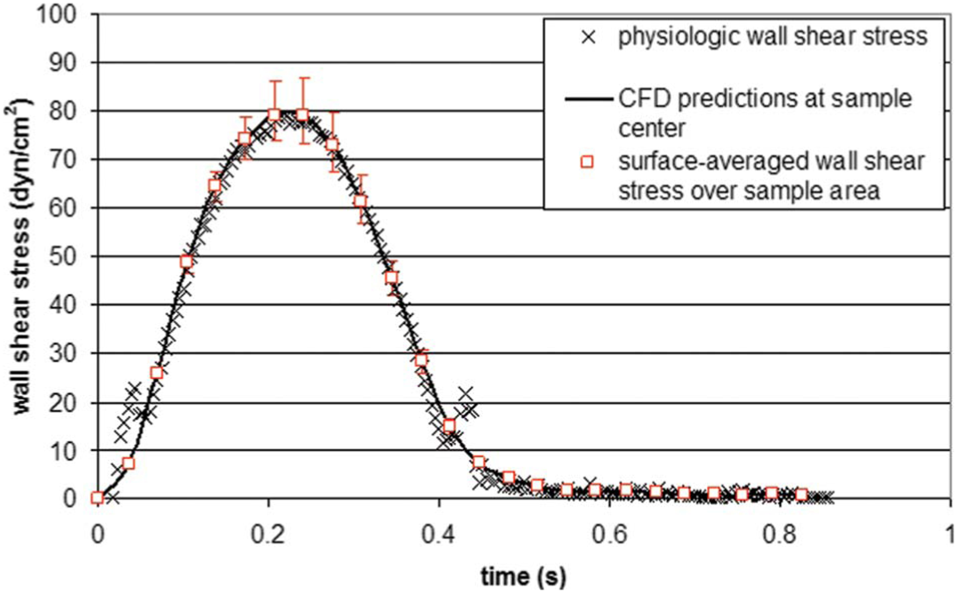
Comparison between the physiologic wall-shear stress experienced by the ventricular surface of an aortic valve leaflet, the wall-shear stress predicted by CFD at the center of the area covered by a tissue sample, and the surface-averaged wall-shear stress predicted by CFD over the sample area. The red markers indicate the maximum and minimum wall-shear stress values computed over the sample area.
LDV.
The measurements of the tangential velocity component (vθ) carried out from the plate to the cone surface at the three radial positions (r=20 mm, r=30 mm, and r=36 mm) are shown in Fig. 5. As expected, the tangential velocity profile captured along each radius is essentially linear. The slope of the profile is determined by the no-slip boundary conditions at the plate (i.e., vθ =0) and the cone (i.e., vθ =rω). At each radius, the point-to-point comparison made between the LDV measurements and the CFD predictions obtained in a similar geometry, under similar operating conditions, demonstrates the agreement between the two techniques and validates the CFD model.
Mechanical Performance.
The validated angular velocity (see Fig. 2(b)) was programed into the servo drive via the software interface motion planner (Parker-Hannifin Corp., Cleveland, OH). In an effort to enhance accuracy on the positioning of the servo motor axis, a period was divided into 100 intervals, and the motion information was entered at each time point in terms of acceleration, velocity, and displacement. Prior to starting the motor, the inertia of the cone and coupling device was input into the servo drive in order to apply the necessary corrections, ensuring that a similar velocity waveform is achieved downstream by the cone. The mechanical validation of the tissue culture system was carried out by comparing the velocity waveform programed into the servo drive and the actual cone velocity output by the servo drive and acquired using labview (National Instruments Corp., Austin, TX). The results shown in Fig. 6 demonstrate the close match between the two waveforms in terms of both magnitudes and time rates. The average error was calculated as 9.8 rpm or 2.0% of the mean cone velocity over one period. The velocity measurements significantly differing from the programed velocity waveform and distributed along the range 0.40⩽t⩽0.86 s (i.e., flat portion of the velocity waveform characterized by low velocities) were investigated. Those points could not be repeated on further measurements. Therefore, their presence was attributed to noise produced by the analog output of the servo drive due to the high sampling rate and the low voltage detected for low velocity measurement. The good match obtained between the programed and actual cone velocity waveforms permitted to validate the tissue culture system in terms of its capability to produce desired cone angular velocity variations and thus desired shear stress variations on the plate surface. Finally, the mechanical validation of the system was investigated in terms of its capability to operate in a temperature environment, complying with the culture of biological tissue. The servo motor was placed in an incubator at a temperature of 37°C and was run for 120 h at the cone angular velocity determined earlier. The motor temperature provided by the analog output of the servo drive was shown to increase from 37°C to 40°C between the beginning and the end of the experiment. Over the same period, the incubator successfully maintained a constant temperature of 37°C, which demonstrates that the temperature increase in the motor did not affect the temperature of the culture environment.
Fig. 6.
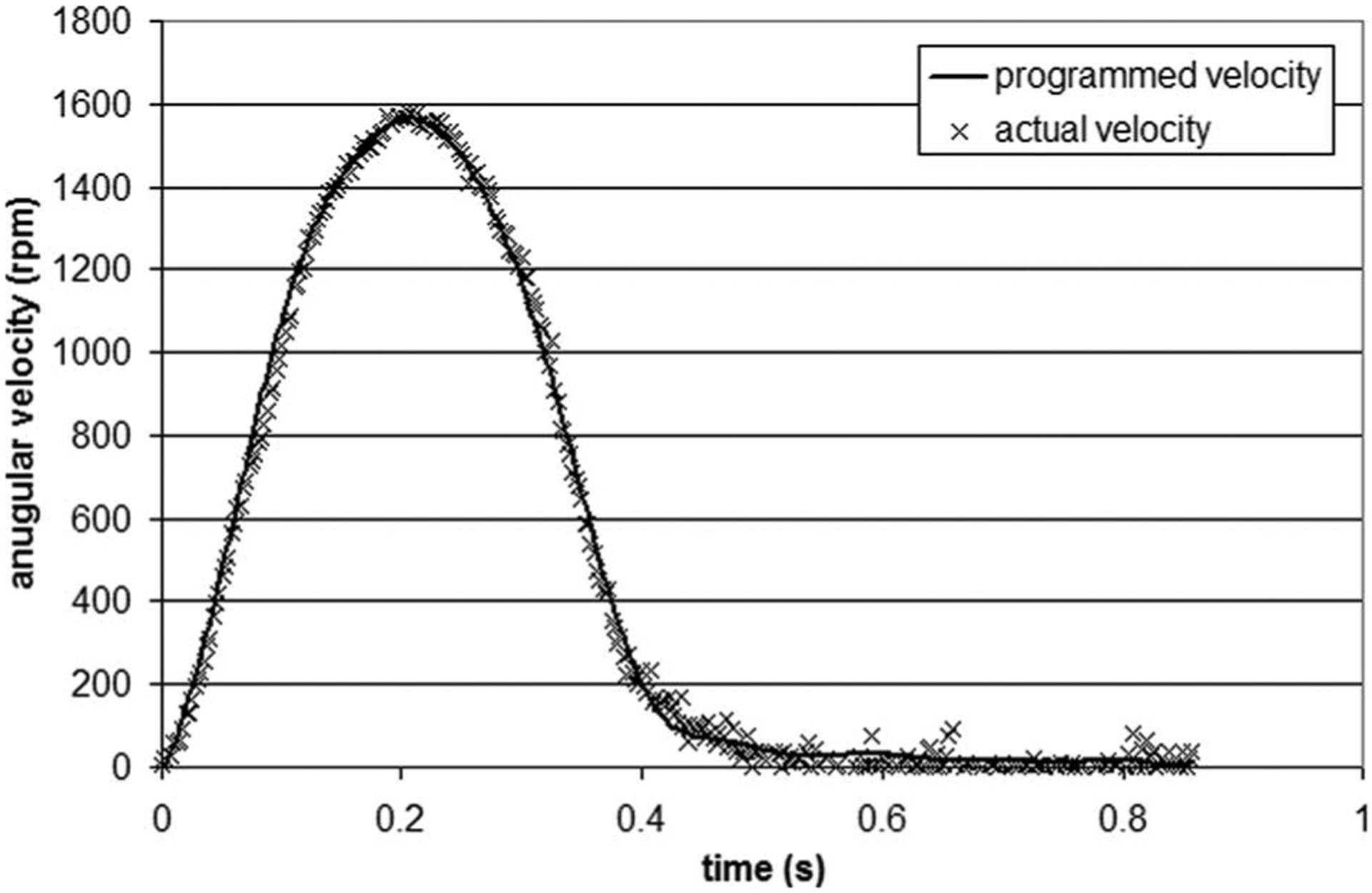
Comparison between the cone velocity waveform programed into the servo drive and the actual velocity measured on the axis of the servo motor over one period
Sterility Test.
The DAPI stain (Fig. 7) shows that normal cell morphology and viability were maintained after culture in the cone-and-plate bioreactor (Fig. 7(b)) when compared to fresh controls (Fig. 7(a)). There were no cell fragments or apoptotic bodies. This demonstrates that the bioreactor was able to maintain the sterility of culture media, as well as the normal morphological characteristics of the cells, for the intended culture duration.
Fig. 7.
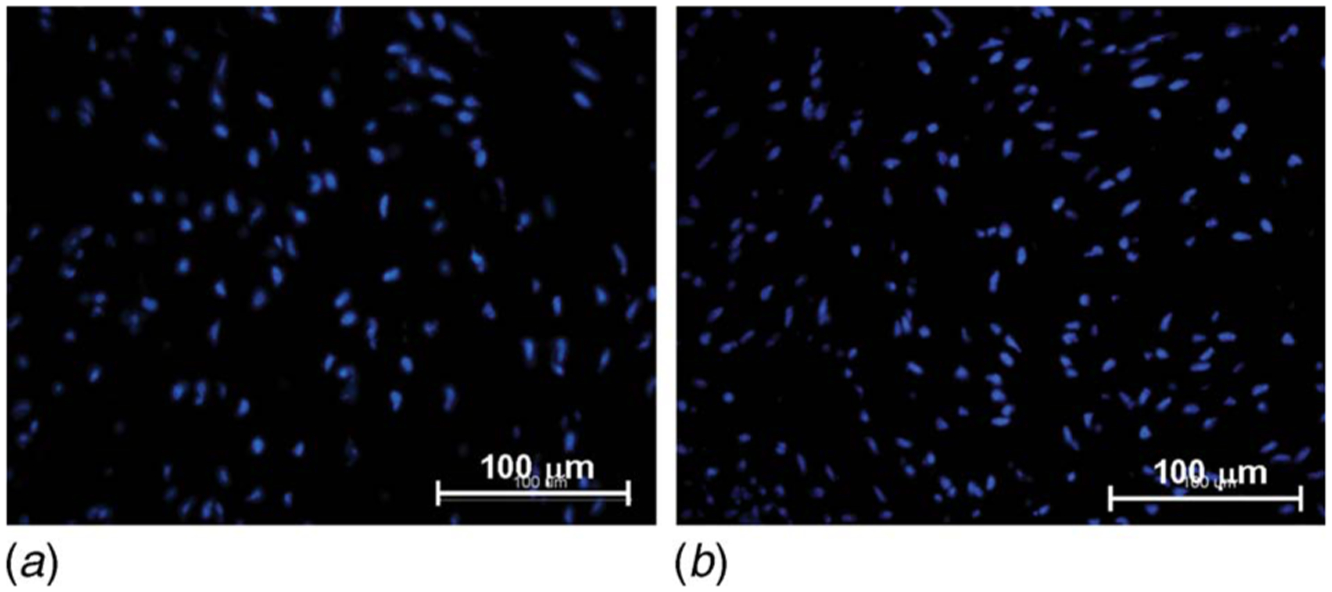
DAPI stain on (a) aortic valve leaflet exposed to physiologic ventricular shear stress conditions for 120 h and (b) fresh control (nuclei stained in blue)
Discussion
In this study, a tissue culture system based on the geometry of a cone-and-plate viscometer has been developed to expose biological tissue to shear stress ex vivo. Although the cone-and-plate apparatus has been extensively used in biomedical applications to expose cell monolayers to a nearly uniform shear stress environment, the present design is innovative since it subjects whole pieces of tissue to time-varying shear stress. The ability to simultaneously expose nine tissue samples to identical shear stress conditions increases the significance of the biological data collected during a single experiment. In addition, the modular nature of the tissue holders allows samples of different thicknesses to be flush mounted in the system, and thus the exposure of various types of tissue to well-defined shear stress conditions. Finally, the whole system is compact enough to fit in a standard incubator and is well suited for long-term experiments in which sterility, gas supply, and temperature control are of importance.
The reliability and capability of the system to produce desired shear stress conditions on the surface of tissue samples have been verified. A validated CFD model has been developed to predict the flow produced in the novel system and to help in the determination of its operating conditions. The computational results demonstrated that the present geometry produced significant secondary flow effects at a Reynolds number as low as 1.66. This result was found to be in agreement with previously published analytical, experimental, and computational results obtained in a similar geometry [27–31]. Although the validation protocol was carried out on aortic valve leaflet tissue, the system can be easily adapted to accommodate other types of tissue. The driving system is powerful and flexible enough to expose tissue samples to shear stress levels ranging from 0 dyn cm−2 to 79 dyn cm−2 and to maintain the tissue in sterile conditions over a period of 120 h. It should be noted that the mounting system described in this paper cannot totally eliminate tiny gaps between the tissue sample and the edge of the plate cover. Although this gap will induce some local flow perturbations, those perturbations are expected to be much less significant than the macroscale perturbations caused by the tissue thickness.
The proposed design could benefit from additional features aimed at improving the control over the biological and mechanical environments. The vertical positioning of the cone with respect to the plate currently achieved by placing two micro-cover-slides on the plate and by securing the cone-shaft assembly via a set screw could be adjusted using the micrometer-driven translating rig developed by Blackman et al. [33]. Tighter control over the culture medium temperature could be achieved by embedding thermo-couples and heating wires in the plate, as described by previous investigators [32–34]. Finally, the replenishment of the culture medium could be done by a continuous perfusion through the device via inlet and outlet ports located on the lateral wall of the plate.
Conclusion
In conclusion, a novel ex vivo shear device has been designed to subject heart valve leaflets to well controlled unsteady or steady shear stress waveforms under sterile conditions. The gas exchange capabilities of the system ensure sufficient transport of nutrients to the tissue samples, allowing for operation over 120 h. This tissue culture system can be used to study the effects of normal (physiologic) and altered (pathologic or pathophysiologic) shear stress on the biology of different types of tissue. This knowledge will provide insights into the biological processes involved in valve disease progression and will help in the design of preconditioning systems capable of optimizing the production of engineered tissue.
Acknowledgment
This research was supported by the American Heart Association under the Postdoctoral Research Award No. 0625620B and the National Science Foundation through the Engineering Research Center program at the Georgia Institute of Technology under Award No. EEC 9731643. The authors would also like to thank Dr. Fotis Sotiropoulos (University of Minnesota) for providing the shear stress data of his aortic valve CFD model, Randy Ankeny for his feedback, and Holifield Farms (Covington, GA) for supplying porcine hearts for this research.
Nomenclature
Symbols
- Rc
cone radius (m)
- Re
Reynolds number (dimensionless)
- T
period (s)
- h
vertical distance between the cone apex and the plate (m)
- n
refractive index (dimensionless)
- r
radial coordinate (m)
- t
time (s)
- vθ
tangential velocity component (m s−1)
- α
angle between the cone and the plate (dimensionless)
- μ
dynamic viscosity (kg m−1 s−1)
- ν
kinematic viscosity (m2 s−1)
- ρ
density (kg m−3)
- τw
wall-shear stress (kg m−2 s−2)
- ω
cone angular velocity (s−1)
Contributor Information
Adnan Elhammali, School of Physics, Georgia Institute of Technology, Joseph H. Howey Physics Building, 837 State Street, Atlanta, GA 30332-0430.
Kartik Balachandran, Wallace H. Coulter Department of Biomedical Engineering, Georgia Institute of Technology, Parker H. Petit Biotechnology Building, 315 Ferst Drive, Suite 2116, Atlanta, GA 30332-0363.
Hanjoong Jo, Wallace H. Coulter Department of Biomedical Engineering, Emory University, 2005 Woodruff Memorial Building, 1639 Pierce Drive, Atlanta, GA 30322-4600.
Ajit P. Yoganathan, Wallace H. Coulter Department of Biomedical Engineering, Georgia Institute of Technology, U.A. Whitaker Building, 313 Ferst Drive, Room 2119, Atlanta, GA 30332-0535
References
- [1].Balachandran K, Konduri S, Sucosky P, Jo H, and Yoganathan AP, 2006, “An Ex Vivo Study of the Biological Properties of Porcine Aortic Valves in Response to Circumferential Cyclic Stretch,” Ann. Biomed. Eng, 34(11), pp. 1655–1665. [DOI] [PMC free article] [PubMed] [Google Scholar]
- [2].Butcher JT, Sorescu G, Jo H, and Nerem R, 2005, “Unique Morphological and Genetic Responses of Valvular Endothelial Cells to Steady Laminar Shear Stress,” Proceedings of the Third Biennial Meeting of The Society for Heart Valve Disease, June 17–20, Vancouver, Canada. [Google Scholar]
- [3].Butcher JT, and Nerem RM, 2006, “Valvular Endothelial Cells Regulate the Phenotype of Interstitial Cells in Co-Culture: Effects of Steady Shear Stress,” Tissue Eng, 12(4), pp. 905–915. [DOI] [PubMed] [Google Scholar]
- [4].Engelmayr GC Jr., Rabkin E, Sutherland FWH, Schoen FJ, Mayer JE Jr., and Sacks MS, 2005, “The Independent Role of Cyclic Flexure in the Early in Vitro Development of an Engineering Heart Valve Tissue,” Biomaterials, 26(2), pp. 175–187. [DOI] [PubMed] [Google Scholar]
- [5].Xing Y, Warnock JN, He Z, Hilbert SL, and Yoganathan AP, 2004, “Cyclic Pressure Affects the Biological Properties of Porcine Aortic Valve Leaflets in a Magnitude- and Frequency-Dependent Manner,” Ann. Biomed. Eng, 32(11), pp. 1461–1470. [DOI] [PubMed] [Google Scholar]
- [6].Ikhumetse J, Konduri S, Warnock JN, Xing Y, and Yoganathan AP, 2006, “Cyclic Aortic Pressure Affects the Biological Properties of Porcine Pulmonary Valve Leaflets,” J. Heart Valve Dis, 15(2), pp. 295–302. [PubMed] [Google Scholar]
- [7].Platt MO, Xing Y, Jo H, and Yoganathan AP, 2006, “Cyclic Pressure and Shear Stress Regulate Matrix Metalloproteinases and Cathepsin Activity in Porcine Aortic Valves,” J. Heart Valve Dis, 15(5), pp. 622–629. [PubMed] [Google Scholar]
- [8].Yoganathan AP, He Z, and Casey Jones S, 2004, “Fluid Mechanics of Heart Valves,” World Futures, 6, pp. 331–362. [DOI] [PubMed] [Google Scholar]
- [9].Weston MW, LaBorde DV, and Yoganathan AP, 1999, “Estimation of the Shear Stress on the Surface of an Aortic Valve Leaflet,” Ann. Biomed. Eng, 27, pp. 572–579. [DOI] [PubMed] [Google Scholar]
- [10].Thubrikar M, 1990, The Aortic Valve, CRC, Boca Raton, FL. [Google Scholar]
- [11].Nugent HM, and Edelman ER, 2003, “Tissue Engineering Therapy for Cardiovascular Disease,” Circ. Res, 92(10), pp. 1068–1078. [DOI] [PubMed] [Google Scholar]
- [12].Hoerstrup S, Sodian R, Daebtriz S, Wang J, Bacha E, Martin D, Moran A, Guleserian K, Sperling J, Kaushal S, Vacanti J, Schoen F, and Mayer J, 2000, “Functional Living Trileaflet Heart Valves Grown in Vitro,” Circulation, 102, pp. 11144–11149. [DOI] [PubMed] [Google Scholar]
- [13].Engelmayr GC Jr., Hildebrand DK, Sutherland FW, Mayer JE, and Sacks MS, 2003, “A Novel Bioreactor for the Dynamics Flexural Stimulation of Tissue Engineered Heart Valve Biomaterials,” Biomaterials, 24, pp. 2523–2532. [DOI] [PubMed] [Google Scholar]
- [14].Warnock JN, Konduri S, He Z, and Yoganathan AP, 2005, “Design of a Sterile Organ Culture System for the Ex Vivo Study of Aortic Heart Valves,” ASME J. Biomech. Eng, 127(5), pp. 857–861. [DOI] [PubMed] [Google Scholar]
- [15].Hildebrand DK, Wu ZJ, Mayer JE Jr., and Sacks MS, 2004, “Design and Hydrodynamic Evaluation of a Novel Pulsatile Bioreactor for Biologically Active Heart Valves,” Ann. Biomed. Eng, 32(8), pp. 1039–1049. [DOI] [PubMed] [Google Scholar]
- [16].Frangos JA, Eskin SG, McIntire LV, and Ives CL, 1985, “Flow Effects on Prostacyclin Production by Cultured Human Endothelial Cells,” Science, 227(4693), pp. 1477–1479. [DOI] [PubMed] [Google Scholar]
- [17].Chappell DC, Varner SE, Nerem RM, Medford RM, and Alexander RW, 1998, “Oscillatory Shear Stress Stimulates Adhesion Molecule Expression in Cultured Human Endothelium,” Circ. Res, 82(5), pp. 532–539. [DOI] [PubMed] [Google Scholar]
- [18].Chiu JJ, Chen CN, Lee PL, Yang CT, Chuang HS, Chien S, and Usami S, 2003, “Analysis of the Effect of Disturbed Flow on Monocytic Adhesion to Endothelial Cells,” J. Biomech, 36(12), pp. 1883–1895. [DOI] [PubMed] [Google Scholar]
- [19].Chiu JJ, Chen LJ, Lee PL, Lee CI, Lo LW, Usami S, and Chien S, 2003, “Shear Stress Inhibits Adhesion Molecule Expression in Vascular Endothelial Cells Induced by Coculture with Smooth Muscle Cells,” Blood, 101(7), pp. 2667–2674. [DOI] [PubMed] [Google Scholar]
- [20].DePaola N, Davies PF, Pritchard WF Jr., Florez L, Harbeck N, and Polacek DC, 1999, “Spatial and Temporal Regulation of Gap Junction Connexin43 in Vascular Endothelial Cells Exposed to Controlled Disturbed Flows in Vitro,” Proc. Natl. Acad. Sci. U.S.A, 96(6), pp. 3154–3159. [DOI] [PMC free article] [PubMed] [Google Scholar]
- [21].Hsiai TK, Cho SK, Reddy S, Hama S, Navab M, Demer LL, Honda HM, and Ho CM, 2001, “Pulsatile Flow Regulates Monocyte Adhesion to Oxidized Lipid-Induced Endothelial Cells,” Arterioscler., Thromb., Vasc. Biol, 21(11), pp. 1770–1776. [DOI] [PubMed] [Google Scholar]
- [22].Mooney M, and Ewart RH, 1934, “The Conicylindrical Viscometer,” Physics (N.Y.), 5, pp. 350–354. [Google Scholar]
- [23].Dai G, Natarajan S, Zhang Y, Vaughn S, Blackman BR, Kamm RD, Garcia-Cardena G, and Gimbrone MA Jr., 2004, “Distinct Endothelial Phenotypes Evoked by Arterial Waveforms Derived from Atherosclerosis-Susceptible and -Resistant Regions of Human Vasculature,” Proc. Natl. Acad. Sci. U.S.A, 101, pp. 14871–14876. [DOI] [PMC free article] [PubMed] [Google Scholar]
- [24].Dewey CF Jr., Bussolari SR, Gimbrone MA Jr., and Davies PF, 1981, “The Dynamic Response of Vascular Endothelial Cells to Fluid Shear Stress,” ASME J. Biomech. Eng, 103(3), pp. 177–185. [DOI] [PubMed] [Google Scholar]
- [25].Go YM, Patel RP, Maland MC, Park H, Beckman JS, Darley-Usmar VM, and Jo H, 1999, “Evidence for Peroxynitrite as a Signaling Molecule in Flow-Dependent Activation of C-Jun NH(2)-Terminal Kinase,” Am. J. Physiol, 277(42), pp. H1647–1653. [DOI] [PubMed] [Google Scholar]
- [26].Jo H, Song H, and Mowbray A, 2006, “Role of NADPH Oxidases in Disturbed Flow- and BMP4-Induced Inflammation and Atherosclerosis,” Antioxidants and Redox Signaling, 8(9–10), pp. 1609–1619. [DOI] [PubMed] [Google Scholar]
- [27].Fewell ME, and Hellums JD, 1977, “The Secondary Flow of Newtonian Fluids in Cone-And-Plate Viscometers,” Trans. Soc. Rheol, 21(4), pp. 535–565. [Google Scholar]
- [28].Pelech I, and Shapiro AH, 1964, “Flexible Disk Rotating on a Gas Film Next to a Wall,” ASME J. Appl. Mech, 31, pp. 577–584. [Google Scholar]
- [29].Sdougos HP, Bussolari SR, and Dewey CF, 1984, “Secondary Flow and Turbulence in a Cone-And-Plate Device,” J. Fluid Mech, 138, pp. 379–404. [Google Scholar]
- [30].Buschmann MH, Dieterich P, Adams NA, and Schnittler H-J, 2004, “Analysis of Flow in Cone-And-Plate Apparatus with Respect to Spatial and Temporal Effects on Endothelial Cells,” Biosens. Bioelectron, 89(5), pp. 493–502. [DOI] [PubMed] [Google Scholar]
- [31].Chung CA, Tzou MR, and Ho RW, 2005, “Oscillatory Flow in a Cone-And-Plate Bioreactor,” ASME J. Biomech. Eng, 127, pp. 601–610. [DOI] [PubMed] [Google Scholar]
- [32].Bussolari SR, Dewey CF Jr., and Gimbrone MA Jr., 1982, “Apparatus for Subjecting Living Cells to Fluid Shear Stress,” Rev. Sci. Instrum, 53(12), pp. 1851–1854. [DOI] [PubMed] [Google Scholar]
- [33].Blackman BR, Barbee KA, and Thibault LE, 2000, “In Vitro Cell Shearing Device to Investigate the Dynamic Response of Cells in a Controlled Hydrodynamic Environment,” Ann. Biomed. Eng, 28(4), pp. 363–372. [DOI] [PubMed] [Google Scholar]
- [34].Blackman BR, Garcia-Cardena G, and Gimbrone MA Jr., 2002, “A New in Vitro Model to Evaluate Differential Responses of Endothelial Cells to Simulated Arterial Shear Stress Waveforms,” ASME J. Biomech. Eng, 124(4), pp. 397–407. [DOI] [PubMed] [Google Scholar]
- [35].Sorescu GP, Sykes M, Weiss D, Platt MO, Saha A, Hwang J, Boyd N, Boo YC, Vega JD, Taylor WR, and Jo H, 2003, “Bone Morphogenic Protein 4 Produced in Endothelial Cells by Oscillatory Shear Stress Stimulates an Inflammatory Response,” J. Biol. Chem, 278(33), pp. 31128–31135. [DOI] [PubMed] [Google Scholar]