

Abstract
Pressure sensors for wearable healthcare devices, particularly force sensitive resistors (FSRs) are widely used to monitor physiological signals and human motions. However, current FSRs are not suitable for integration into wearable platforms and are expensive to process. This work presents a novel technique for developing textile force sensitive resistors (TFSRs) using a combination of inkjet printing of metal-organic decomposition silver inks and heat pressing for facile integration into textiles. The TSFR structure consists of a thermoplastic polyurethane (TPU) membrane sandwiched between two nonwoven textiles with inkjet printed electrodes. The insulating void between the top and bottom electrodes creates an architectured piezoresistive structure. The structure functions as a simple logic switch where under a threshold pressure the electrodes make contact to create conductive paths (on-state) and without pressure returns to the prior insulated condition (off-state). The TFSR can be controlled by arranging the number of layers and hole diameters of the TPU spacer to specify a wide range of activation pressures from 4.9 kPa to 7.1 MPa. For a use-case scenario in wearable healthcare technologies, the TFSR connected with a readout circuit and a mobile app shows highly stable signal acquisition from finger movement. According to the on/off state of the TFSR with LED bulbs by different weights, it can be utilized as a textile switch showing tactile feedback. When integrated with a physical device or object, the sensor design has a high potential for registering tactile interaction as a means to quantify health-related behaviors such as medication adherence or use of a self-monitoring device.
Keywords: E-textiles, inkjet printing, piezoresistive sensor, force sensitive resistor, wearable healthcare device, flexible electronics
1. Introduction
Wearable sensors are a critical topic in not only the textile industry, but in other industries with increasing consumer demands in wearable and flexible healthcare devices.[1] Wearable healthcare devices have the ability to detect symptoms of diseases continuously outside of clinical settings, lowering costs and enabling healthcare providers to personalize medical care for each patient.[2] The use of these devices may also generate an improvement of medical compliance and adherence by encouraging people to pay more attention to their health through interactive user interfaces provided by wearable technologies.[3] There have been various wearable sensors for healthcare monitoring to detect and analyze different parameters such as temperature[4], pressure/strain by body motions[5], electrocardiography[6], and biomarkers in biofluids (i.e. saliva, sweat, tear).[7] Among these sensors designed for various stimuli, interactive haptic devices are one of the key components at the interface between humans and flexible healthcare devices.[8] Pressure sensors with force sensitive properties provide key functionality for numerous healthcare device applications. Previous works in flexible and wearable healthcare devices focused on transducing mechanical forces generated from small external stimuli, such as grip or touch, into electrical responses. This was beneficial for monitoring physiological signals such as radial artery pulse[9], respiration[10,11], and body movement.[12] In addition, integration of the pressure sensors with VR (virtual reality) and AR (augmented reality) introduces future rehabilitation therapies that are both more recreational and effective.[8] While various working principles of pressure haptic sensors have been studied (i.e. piezoresistive[13–15], capacitive[16–18], piezoelectric[19–22], and triboelectric pressure sensors[23–25]), piezoresistive sensors and force sensitive resistors are particularly beneficial due to their high sensitivities when converting external pressures into discernable electronic signals as shown in Table 1. However, these piezoresistive sensors require high electrical conductivity over large surface areas with micro or nano-scale structures in order to meet the high sensitivity for reliable applications.[14,15,26]
Table 1.
Summary of the performance of pressure haptic sensors reported in the literature
| Sensing Mechanism | Active Materials | Detection Regime | Sensitivity | Form Factor | Ref. |
|---|---|---|---|---|---|
| Piezoresistive | Inkjet printed Ag | 4.9 kPa – 7.1 MPa | R/R0 ≈ 10−6 | 1 × 1 cm2 (Textile) | In this study |
| Screen printed Ag | < 6 kPa | R/R0 ≈ 0.80 | 1 × 4 cm2 (Textile) | [10] | |
| Ag threads | 3 kPa – 1.4 MPa | - | 2.7 × 2.5 cm2 (Textile) | [11] | |
| Dip coated Ag nanowires |
< 30 kPa | I/I0 ≈ 106 | 5 × 5 mm2 (Textile) | [32] | |
| Sngle-walled carbon nanotubes | < 0.3 kPa | 3.26 kPa−1 | 15 × 15 μm2 (Film) | [14] | |
| Au nanowires | < 0.6 kPa | 23 kPa−1 | 10 × 10 cm2 (Film) | [15] | |
| Capactivie | Silicone elastomer, Ecoflex | < 10 kPa | 0.148 kPa−1 | 15 × 15 mm2 (Film) | [16] |
| Polydimethyl-siloxane (PDMS) | < 10 kPa | 0.55 kPa−1 | 8 × 8 mm2 (Film) | [17] | |
| Polydimethyl-siloxane (PDMS) | < 20 kPa | 0.21 kPa −1 | 2 × 1.5 cm2 (Textile) | [18] | |
| Piezoelectric | Lead zirconate titanate (PZT) | < 10 Pa | 5 μA/Pa | 1 × 1 cm2 (Film) | [21] |
| Poly(vinylidene fluoride) (PVDF) | < 20 kPa | 0.377 V/N | 15 × 15 mm2 (Film) | [22] | |
| Triboelectric | Polytetrafluoroethylene (PTFE) | 5 – 50 kPa | 127.2 mV/kPa−1 | 1 × 1 cm2 (Film) | [24] |
| Polydimethyl-siloxane (PDMS) | < 1 kPa | 150 mV/Pa | 33 × 33 mm2 (Film) | [25] |
Electronic textiles (e-textiles) are one of the effective strategies for meeting the requirements of wearable and flexible healthcare devices that can be integrated into daily products. E-textiles are textile-based structures so they are expected to be especially beneficial for flexible and wearable pressure sensor applications compared to rigid substrates such as silcon wafers or glasses, due to their flexibility, stretchability, durability, breathability, washability, and high durability under extreme mechanical deformations.[27] Additionally, e-textiles have garnered attention as next-generation electronics due to their facile integration into textiles or fabrics as components and interconnects of wireless and wearable devices.[28–32] These inherent properties make textiles an ideal platform to create conformable and wearable sensors that rely on flexible circuitry because wearable sensors are usually attached to the human body or an object and interact with external devices to provide feedback.[33]
Although there are several studies that developed force sensitive resistors on textiles using screen-printing of Ag paste[10], sewing of Ag threads[11], coating of Ag nanowires[34], 3D printing of conductive composite[35], chemical vapor deposition (CVD) growth of CNT[36], and self-bondable Ag nanoparticles/polyurethane hybrid conductive fibers[37], the high-cost and time-consuming fabrication processes make sensor integration with wearable devices challenging for large scale production. Therefore, it is highly desirable to apply a cost-effective and straightforward procedure to deposit conductive layers on textile substrates to construct piezoresistive sensing structures.[38–40] Inkjet printing, based on a digital printing process, is a feasible solution to overcome the aforementioned limitations because it does not require masking, minimizes material and time waste by utilizing drop-on-demand (DOD) methodology, and creates higher resolution patterns derived from 1–10 pL drops of low viscosity inks.[41] Furthermore, inkjet printing of metal-organic decomposition (MOD) silver inks[42] allows the printing of automated and scalable patterns onto textile substrates with high electrical conductivity and large surface area due to the inherent surface roughness of textiles[43], both of which are requirements for highly force sensitive resistors. Also, MOD silver ink enables the deposition of thin layers on individual fibers and minimizes nozzle clogging due to the absence of nanoparticles in the inks.[44,45]
Aside from the deposition of conductive materials onto substrates, device assembly is another crucial process that governs the performance and durability of FSRs. As piezoresistive sensors, the architected sensor structure typically consists of two conductive layers and a spacer layer. When an external loading above a certain threshold is applied onto the piezoresistive sensor, the contact area changes between the two conductive electrodes and forms conductive paths between them. Therefore, high conductivity is required to create sensors with high sensitivities in low applied force regimes.[12,13] It is also important to consider the interface behavior of the insulating layer in the piezoresistive sensor since resilience, adhesion properties, and flexibility are key factors in the device assembly stage.
In the specific use of textile-based pressure sensors as flexible healthcare devices, touch sensing gloves with pressure sensor arrays were developed to assess fine motor skills of children with autism spectrum disorder objectively, where the clinical screening method uses the finger tapping test.[46] In addition, it is possible to monitor muscular tremors or stiffness due to neurological disorders by using wearable pressure sensors.[47] On the other hand, micro-pressure sensors have been utilized within contact lenses for short-term monitoring of glaucoma patients’ intraocular pressure.[48] However, monitoring the compliance with medication for glaucoma is also crucial for the treatment progression and long-term therapy goals of glaucoma patients.[49,50] At least 50% of patients have difficulty in patient-administration of topical medication, and they rarely adhere to dosing recommendations.[51] Failure of adherence to dosing significantly limits the effectiveness of eye drops. Although a few previous studies suggested solutions by using pressure sensors to monitor the squeezing motion of patients[52,53], these sensors are designed for single bottle usage, which is not suitable for continuous patient monitoring nor it is cost-effective to fabricate new sensors for the future bottles. In addition, these works did not evaluate the reliability of the signal by real human motions and the durability against repeated uses. So, there exists a critical need to develop a wireless and reusable pressure sensor capable of detecting pressures applied to the bottles while squeezing. This will allow for continuous collection of real-time behavioral data to guide care management interventions and treatment strategy adjustments.
Here, we developed a textile force sensitive resistor (TFSR) with a simple structure but wide applicability in flexible and wearable healthcare devices. Our TSFR employs two inkjet printed electrodes sandwiched between a TPU membrane with various vacancy sizes. Thus, our fabrication process is a facile two-step approach of inkjet printing and heat pressing to build textile-based sensors. We take advantage of the porous structure of inkjet printed electrodes on nonwoven fabrics and the adhesion of TPU film spacer layers between the top and bottom electrodes, to dictate the electrical resistance response by controlling the TPU membrane thickness and vacancy sizes. The threshold pressure of the TFSR can be controlled by specifying the number of layers and hole diameter of the TPU spacers. For the durability and comfort of wearable devices, both washability and breathability was demonstrated using standardized test methods. Based on the use-case scenario of the TFSR, the sensor was integrated into a circuit as a textile switch powering up light-emitting diode (LED) bulbs. This sensing property can be applied to tactile feedback applications and healthcare mobile applications such as detecting finger motion and the amount of remaining medication in an eyedropper bottle.
2. Results and Discussion
2.1. Working principle of Textile Force Sensitive Resistor (TFSR)
Figure 1 (a) illustrates the fabrication process and the final structure of the textile force sensitive resistor (TFSR), which consists of two inkjet printed electrodes and a sandwiched TPU spacer between them. We used metal-organic decomposition (MOD) silver ink with high electrical conductivity for inkjet printing, which shows 0.35 ± 0.13 Ω/sq sheet resistance on the nonwoven fabric. According to the chemical reaction shown in Figure 1 (b), the subsequent annealing process after inkjet printing is required to fabricate uniform layers of elemental silver on the entire surface of fibers.[44] Unlike other conductive inks such as silver nanoparticles, MOD silver ink enables the deposition of conformal conductive layers on textile fibers as shown in the SEM and EDS analysis images (Figure S1, Supporting Information). The conformal coating mechanism with the inkjet process allows our nonwoven textiles to achieve high electrical conductivity while maintaining their inherent mechanical properties, including flexibility as shown in Figure 1 (c). For the construction of the TFSR structure, we heat pressed a thermoplastic polyurethane (TPU) membrane to serve as a spacer and binder between the top and bottom inkjet printed electrodes. TPU membranes are widely used for lamination by heat pressing to encapsulate conductive interconnects on flexible substrates.[30,54] They can be crafted into different patterns with a laser cutter and firmly adhered onto a substrate after heating above its melting temperature. We chose heat pressing because it is a widely used technique to easily integrate textiles with functional materials as a facile and cost-effective process.
Figure 1. Fabrication and Working Principles of the Textile Sensitive Force Resistor (TSFR).
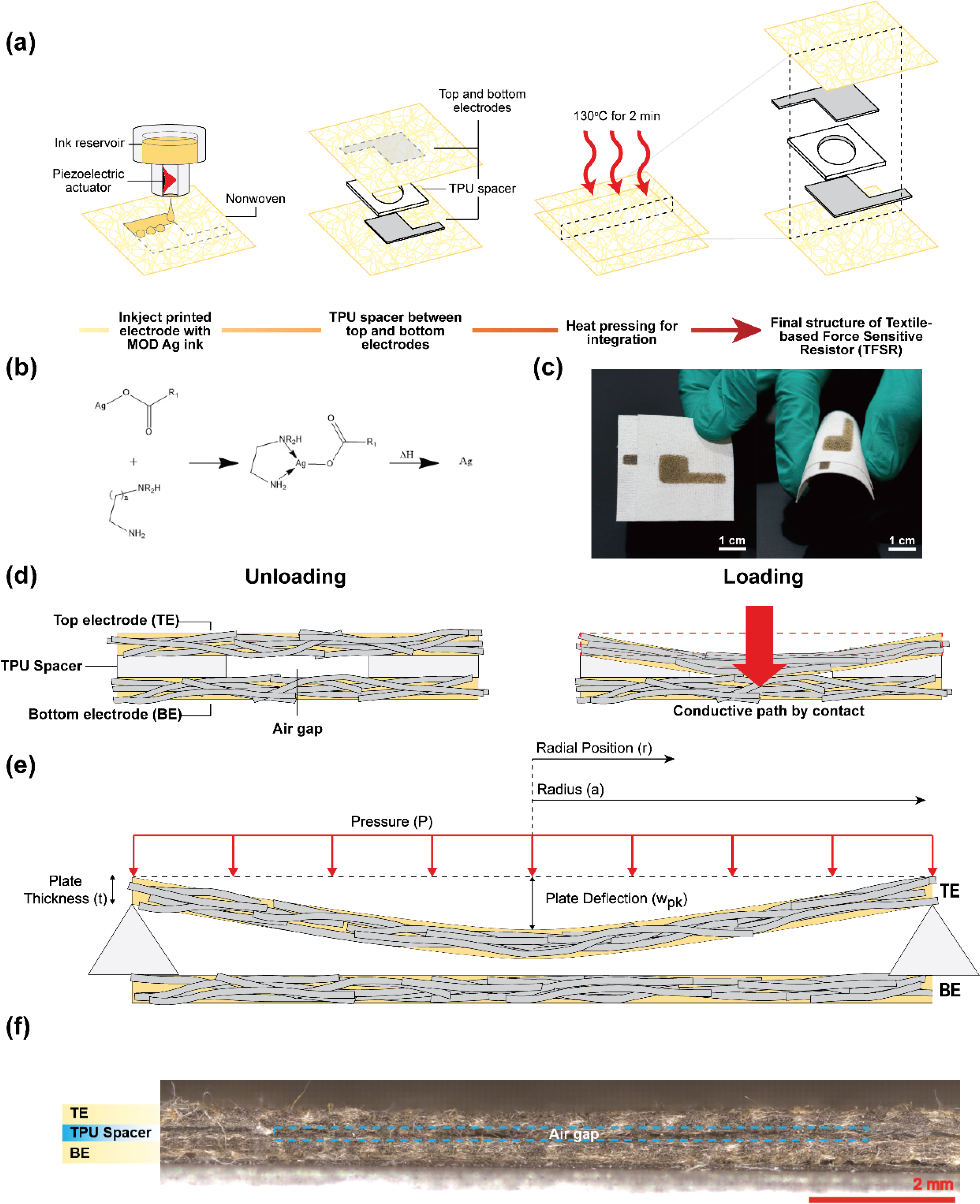
(a) Schematic illustration of the fabrication process and final structure of the TFSR. First, MOD silver ink is inkjet printed onto nonwoven textile substrates to make top and bottom electrodes. Then, a TPU spacer is aligned between the top and bottom electrodes and subsequently heat pressed to give the final structure of the TFSR. (b) Chemical reaction mechanism of the MOD silver ink while curing at 130 °C. (c) Optical images showcasing the flexibility fo the TFSR while bending. (d) Schematic cross-sectional diagram of the working principle of the TFSR during unloading and loading of pressure. (e) A theoretical model of an ideal circular plate assuming the top electrode of the TFSR as a plate. (f) Microscopic cross-sectional image of the TFSR using a wide range of laser confocal scanning.
The working principle of the TFSR is based on the mechanisms governing piezoresistive sensors with architected structures. Due to the presence of the TPU spacer between the top and bottom electrodes, there is a void that creates an electrically insulating area between the two electrodes. Without any pressure on the sensor, the top and bottom electrodes are not in contact due to the TPU spacer between them (Figure 1 (d)). When applying pressure, the electrodes contact each other after a threshold pressure is surpassed, forming a conductive path and a significant decrease in electrical resistance. We defined the threshold pressure of the TFSR as the point when the resistance drastically decreases while continuously increasing the applied pressure. The resistance of the TFSR recovered to a non-conductive state after the release of pressure. The reversible non-conductive and conductive states of the TSFR allow it to function as a simple logic switch where the non-conductive state is the “Off-State” and the conductive state is the “On-State”. To further understand the working mechanism of the TSFR, Figure 1 (e) shows the TSFR can be explained by plate theory.[55] Assuming that the TFSR is based on a circular membrane under uniform pressure and the top electrode acts as the plate, plate theory can be applied using Equation 1, where the deflection of the plate (w(r)) is a function of plate radius, , radial position, , and flexural rigidity of the plate material, .
| (1) |
The flexural rigidity is given by Equation 2, in which , and are the thickness, Poisson’s ratio, and Young’s modulus of the plate material, respectively.
| (2) |
According to Equation 1, is the maximum plate deflection at the center of the plate( = 0). Then, we derived the threshold pressure of the TFSR, given by Equation 3. At the threshold pressure, the amount of deflection should be similar or greater than the thickness of the TPU spacer in order for the top and bottom electrode to contact, leading to a decrease in resistance. Here, we assume that is same as the thickness of the TPU spacer, and is the radius of the hole on the TPU spacer. Thus, according to equation 3, the threshold pressure of the TFSR is controlled by the thickness and hole diameter of TPU spacers theoretically.
| (3) |
2.2. Microscopic Analysis of the TFSR
To further understand the role of thickness and hole diameter of the TPU spacer on the threshold pressure of the TSFR, we created a factorial design of experiments with various hole diameters and the number of TPU layers to observe the changes in threshold pressure (Table 2). The hole diameters ranged from 0.2 cm to 0.8 cm, and the thickness of the TPU spacers was controlled by the number of stacking layers, as shown in Table 2. According to microscopic cross-sectional images of the TFSRs (Figure 2), the thickness of single-layer, double-layer, and triple-layer TPU spacers sandwiched between the electrodes was 67.3 μm, 138.4 μm, and 222.5 μm, respectively. We observed that the TFSRs with more TPU layers had a bigger void between the top and bottom electrodes at the center of the TFSRs due to greater thickness at the center (Figure 2 (d)–(f)). However, when applying pressure onto the TFSRs, the thickness decreased to an almost constant value (≈ 639.9 μm) regardless of the number of TPU layers, indicating that the electrodes were entirely in contact.
Table 2.
Fabrication conditions of the TFSRs with the various number of layers and hole diameters of TPU spacers based on factorial experimental design. (R1–4, R2–4, R3–4, and R1–1 were used representatively to demonstrate the applications of the TFSRs)
| Fabrication Conditions | The hole diameter of TPU spacers (cm) | ||||
|---|---|---|---|---|---|
| 0.2 | 0.4 | 0.6 | 0.8 | ||
| Number of layers of TPU spacers | 1 | R1–1 | R1–2 | R1–3 | R1–4 |
| 2 | R2–1 | R2–2 | R2–3 | R2–4 | |
| 3 | R3–1 | R3–2 | R3–3 | R3–4 | |
Figure 2. Microscopic Images of TFSR Samples with Various Fabrication Conditions and Observed Positions.

(a-c) Cross-sectional images of the TFSR with 1, 2, 3 layers of the TPU spacers at the edge with unloading. (d-f) Cross-sectional images of the TFSR with 1, 2, 3 layers of the TPU spacers at the center with unloading. (g-i) Cross-sectional images of the TFSR with 1, 2, 3 layers of the TPU spacers at the center with loading pressure. All imaged samples were fabricated using TPU spacers with a 0.8 cm hole.
2.3. Electromechanical Performance of the TFSR
Electromechanical performance of the TFSRs was evaluated with a universal tensile machine (UTM)’s compression mode and a multimeter with simultaneous real-time data acquisition and storage (Figure 3 (a)). At the threshold pressure, the resistance of the TSFRs drastically decreased by five to six orders of magnitude. The dramatic decrease in resistance shows that the developed TFSRs have an on/off switching function and high relative resistance (R/R0) of 10−5. The initial resistance, R0, was out of the range detected by the multimeter, so it is assumed that the value of R0 was 1 MΩ for the calculation. The TFSR made of one layer TPU spacer with a hole diameter of 0.8 cm (R1–4) showed a drastic resistance decrease at the threshold pressure of 4.9 kPa. On the other hand, the TFSR made of two TPU spacer layers and a hole size of 0.8 cm (R2–4) showed a higher threshold pressure (33.6 kPa) compared to the single layer of TPU spacer in the sample, R1–4. The TFSR with three sandwiched layers of TPU spacers (R3–4) showed the highest threshold pressure (63.6 kPa) among the samples with the same hole diameter of 0.8 cm (Figure 3 (b)). As shown in Figure 3 (c), the threshold pressure increases as the number of TPU layers increases in different hole diameters. Increasing the number of TPU layers increases the void between the top and bottom electrodes as we discussed in the previous section. Thus, the TFSRs with additional layers of TPU required higher pressure to form close contact and conductive pathways between the electrodes.
Figure 3. Electromechanical Characteristics of the TSFR.

(a) Schematic illustration of the electromechanical characterization setup for the TFSRs. (b) Relative electrical resistance changes and (c) Threshold pressure values of the TFSRs with various layers of TPU spacers (1 layer, 2 layer, and 3 layer) under pressure. (d) Relative electrical resistance changes, and (e) Threshold pressure of the TFSRs with various TPU spacer hole diameters (0.2 cm, 0.4 cm, 0.6 cm, and 0.8 cm) under pressure.
Further investigation into the role of hole diameters showed that the threshold pressure of the TFSRs decreased with increasing hole diameter of the TPU spacer (Figure 3 (e)). The TFSRs made of one layer of the TPU spacer with 0.8 cm, 0.6 cm, 0.4 cm, and 0.2 cm showed their threshold pressure at 4.9 kPa, 5.0 kPa, 63.6 kPa, and 82.4 kPa, respectively. However, the TFSR with a hole diameter of 1.0 cm had no significant threshold point in a low range of pressure. (Figure 3(c)) At the TPU spacers with hole diameters larger than 0.8 cm, the inherent flexibility of the nonwoven fabric dominates and the textile electrode naturally bends due to gravity. The bending phenomenon creates undesirable deflection even without the application of any external pressure, thus we observe no threshold pressures for hole diameters larger than 0.8 cm. The trend of the threshold pressure related to the number of layers and hole diameter of the TPU spacers corresponds to the theoretical equation given by Equation 3. The threshold pressure of the TFSR with hole diameters of 0.6 and 0.8 cm showed a linear increase in TPU spacer thickness. Also, the diameter of the TPU spacer showed much higher sensitivity to the threshold pressure. The increased sensitivity is because the threshold pressure of the TFSR is directly proportional to the thickness () of the TPU spacer, but inversely proportional to the fourth power of the hole diameter () according to Equation 3 (Figure S2, Supporting Information) Therefore, the electromechanical performance of the TFSRs suggests that the developed sensors could work as reliable pressure sensors in a wide range of pressures ranging from 4.9 kPa to 7.1 MPa by simply controlling the thickness and hole diameter of the TPU spacer.
Above the threshold pressure, the resistance gradually decreased with the increase of the applied pressure due to the contact between each silver-coated fiber (Figure S3, Supporting Information). This attributes to the inherent properties (i.e. flexibility, porosity) of the textiles maintained by encapsulation of the individual fibers with inkjet printed MOD silver inks[43,44] Since nonwoven textile materials have natural resilience and porosity, the compressional force would relocate individual fibers to form compact arrays. When the compressional forces are removed, the fiber complexes return back to their initial positions, much like an elastic spring. Overall, we are able to fabricate highly flexible and durable TFSRs by utilizing the desirable inherent properties of textile materials and inkjet processing to maintain individual fiber interstices and mobility. At extremely high pressure, which is much higher than the threshold pressure, the resistance of the TFSR showed relatively constant because no further fiber relocation occurred. For the typical TFSR (R1–4), the resistance converged to approximately 30 Ω under pressure over 100 kPa. The resistance of the compressed TFSRs at the high pressure was similar to the resistance of a single electrode, suggesting that silver-coated fibers of electrodes were almost in complete contact.
2.4. Durability and Comfort of TFSR
Durability is one of the most critical factors for practical applications of pressure sensors. The durability of the TFSR was evaluated by measuring its resistance change while 15 N of compressional force was applied with loading and unloading cycles (0.5 Hz). The results showed resistance responses with high stability and reproducibility during 1000 cycles of pressing (Figure 4 (a)). The low change in resistance after cycling makes the TSFRs suitable candidates for on/off switches. Furthermore, the resistance of TFSR at on-state and off-state maintained a consistent response. This is because of the maintained textile and TPU’s inherent resilience even after inkjet printing and lamination processes. Also, the TFSR showed a quick response and recovery time of ~ 0.1s during loading and unloading of the pressure (0.1 s), which is the limit of the sampling rate of the equipments. (Figure S4, Supporting Information).
Figure 4. Durability and Comfort Performance of the TSFR.

(a) Applied force and relative electrical resistance changes in real-time for 1000 cycles with a tapping frequency of 0.5 Hz. (b) Relative electrical resistance changes after various washing cycles based on AATCC D61; accelerated washing test, and (c) Air permeability of a single-layered untreated nonwoven, a double-layered untreated nonwoven, a TPU spacer and the TFSR made of one layer TPU spacer with the hole diameter of 0.8 cm (R1–4). All samples are characterized under an applied force of 15 N, which equals 118 kPa.
Although the TSFR shows a reliable and stable response after consecutive compression cycles, e-textile devices need to be washable and breathable when considering comfort factors based on human use case scenarios. Washability of the TFSR was evaluated following the AATCC 61D standard for accelerated washing. Based on the standard, one accelerated washing cycle is equivalent to five regular wash cycles using a commercial laundry machine. As shown in Figure 4 (b), after five washing cycles, the TFSR still exhibited a good on/off-switching response with repeated applied pressures without any further encapsulation, even though the electrical resistance slightly increased due to the delamination of the silver layer from the surface of the fibers by mechanical abrasion during washing.[44] However, after ten washing cycles, the resistance change of the TSFR showed a lower response with repeated applied pressures when compared to five washing cycles as the TPU membrane stopped functioning as a spacer and adhesive material between the top and bottom electrodes. The TPU film that we used has a single-side adhesive layer for heat pressing. If we can use the TPU film with adhesive layers on both sides and a larger size for integration, we believe that the washing durability of the device will be improved.
To understand the comfort properties of our TSFR, we measured the air permeability of untreated single and double-layered nonwoven fabrics, the TPU spacer, and TFSR as seen in Figure 4 (c). The air permeability of the TFSR was not significantly affected by the inkjet printing process of the electrodes on the substrate and the TPU spacer between them. This is related to the thin Ag layer deposited onto the surface of individual fibers, maintaining their original fiber structure after inkjet printing. Also, the design of the TFSR, including the TPU spacer with a hole, allows itself to be breathable even though the TPU member is totally impermeable. So, the technique and structure of this sensor applied in this study showed that breathable and wearable sensory applications are possible using textile platforms.
2.5. Application of the TFSR
Our TFSRs show outstanding compressional force sensing capabilities and have many applications for flexible and wearable healthcare systems. For example, our TSFRs can measure finger or hand motions, bending motions, and weight all while maintaining inherent flexibility and wearability of textile materials. As a use-case scenario development for wearable devices, we selected the TFSR made of one layer TPU spacer and a hole diameter of 0.8 cm (R1–4). This sample showed the highest sensitivity against pressure and was thus used to demonstrate a wearable sensing application. For the demo, the TFSR was connected to a circuit and mobile application from Retinal Care Inc. The readout circuit contained both an on-board data processor and a Bluetooth system designed to bridge the interaction between fingertip compression and the mobile applications with the data processor to monitor the real-time pressure response. The Bluetooth data transmission and the mobile app allowed for real-time logging of the TFSR data while changing the pressure onto the TFSR (Figure 5 (a)). The resistance change of the TFSR by finger tapping at a rate of 0.5 Hz was amplified and converted to a digital signal called FSR signal. The FSR signal was recognized by the computer as shown in Figure 5 (b). The pressure change due to finger tapping was successfully monitored using the TFSR integrated with the readout circuit by the digital FSR signal change (a.u.) between on and off-states on the order of 102 (Video S1, Supporting Information). In this demonstration, the TFSR has great potential as a wearable pressure sensor to monitor body movement, especially finger touch or gripping. The fabrication process of our sensor using only inkjet printing and heat pressing is much more cost-effective and straightforward than other devices fabricated by photolithography or electrodeposition for detecting pressure.[38,39] Also, this device can be seamlessly integrated with the textile structure without additional procedure so that it can simplify the circuit preparation process and reduce the integration cost. It is possible to integrate the TFSR into human-computer interactive systems incorporating wearable devices such as detecting breathing, acoustic sound, and body motions.[10,11,34]
Figure 5. Use-Case Scenarios of the TSFR for Textile-Based Wearable Healthcare Applications.

(a) the optical image of the wearable pressure sensor based on the Bluetooth transmission system and the screenshot of the mobile phone application in real-time. (b) FSR signal of the pressure sensor while finger tapping the TFSR at a rate of ~0.5 Hz. (c) Electrical diagram of an inkjet printed circuit with embedded LEDs and TFSRs, and (d) the activation and inactivation demonstration of the TFSRs with different threshold pressure (R1–1; 82.4 kPa, R3–4; 63.6 kPa, R2–4; 33.6 kPa, R1–4; 4.9 kPa) by various weights (500 g, 250 g, 100 g, 30 g), respectively. (e) Schematic image and the FSR signal of the TFSR wrapped around the eye drop bottle to detect squeezing motion, and (f) Schematic image and the on/off-state of the TFSR at the bottom of the eye drop bottle to the remaining amount of the medication.
Our TFSR can also be used as a textile-based logic switch. The inkjet printed TFSR arrays can respond to pressure changes by generating output signals with corresponding pressure in wearable devices. To demonstrate the logic switch capabilities of our TSFR, two inkjet printed textile circuits as top and bottom electrodes were integrated with a 1 × 4 TFSR array on 15 × 15 cm2 of the nonwoven substrate. In addition, LED displays were connected to the TFSRs through the printed paths, respectively (Figure 5 (c)). Each of the TFSRs have different threshold pressures (R1–4; 4.9 kPa, R2–4; 33.6 kPa, R3–4; 63.6 kPa, R1–1; 82.4 kPa). This change in threshold pressure was achieved by controlling the thickness and hole diameter of the TPU spacers. The role of these parameters on threshold pressure is well discussed in sections 2.1 – 2.3 of this manuscript. The final textile switch sensing array showed maintained flexibility, enough such that the array could be folded like the pristine state of the nonwoven textile. When pressing a targeted textile switch, a corresponding LED was lit to provide a visualization of the conversion from external pressure to visible readable signals. The lightning response of the pressure sensor array touched by one or two fingers can be visually observed (Video S2, Supporting Information). It is notable that the user-interactive system is sensitive enough that we can identify the external pressure immediately based on the lightning of the LEDs when weights of different mass were placed on the sensor array. Due to the different threshold pressure of each TFSR, each of LEDs was turned on by 30, 100, 250, and 500 g corresponding to 0.29, 0.98, 2.45, and 4.90 N, respectively, as shown in Figure 5 (d). We can recognize the different colors from the LED after placing the different weights onto the sensing array. Based on this result, the textile switch by the TFSRs can be used for weight or pressure recognition of the human body or any weighted object. With a weight less than the threshold of the specific TFSR, the LED was not activated. By expanding the number of the TFSRs and area of the printed circuit, we can also fabricate a large-scale wearable sensor to detect pressure distributions.[11]
As a proof of concept for a practical healthcare application of the TFSR, we demonstrate a bottle-integrated design for glaucoma medication consisting of a TFSR wrapped around the bottle (Figure 5(e)) and a TSFR placed at the bottom of the bottle (Figure 5(f)). According to previous research reports[56], the average force to grip an eye drop bottle is 10.1 ± 4.0 N. Our developed sensor, depending on the thickness and hole diameter of the TPU spacer, can detect applied forces ranging from 0.6 N to 772 N, which widely encompasses the range of gripping forces used by conventional eyedroppers. Based on the results in this research, we evaluated the ability of the TFSR to detect finger tapping and pressure by different weights via benchtop testing scenarios. Now to evaluate the TSFR’s ability for a practical application, we wrapped a TFSR around the side of an eyedropper bottle to monitor finger gripping, which can then determine whether a patient actually squeezes a proper dose of medication from the eyedropper. As shown in Figure 5 (e), the TFSR connected to the prototype circuit clearly detected the squeezing motion. It is also possible to be used as an indication for the remaining amount of the medication inside from the TFSR at the bottom. (Figure 5 (f)) When the remaining amount of liquid inside the bottle was depleted, there was not enough pressure on the bottom of the bottle. Thus, the TFSR converted from the on-state to off-state because the weight of the bottle, including the medication, cannot apply pressure over the threshold pressure of the TSFR (Figure 5 (f)). This result indicates that patients can easily get interactive feedback to determine whether the bottle requires to be refilled or replaced, by simply placing the eyedropper onto the TSFR device. Overall, our TSFR pressure sensor shows great potential to be used as a bottle-integrated device such as a bottle cover or koozie. The simple and inexpensive integration of the TFSRs is designed to provide feedback to patients and care coordinators while glaucoma patients interact with their eye drop bottles. The novel mining of motion and weight change while tracking patient adherence and behavioral data can be integrated with an existing care coordination framework. This is an important advance in healthcare devices to monitor the gripping motion while using eye droppers for glaucoma patients.
3. Conclusion
In this work, we developed a textile force sensitive resistor (TFSR) using a combination of inkjet printing of metal-organic decomposition silver ink onto nonwoven textile substrates and heat pressing of TPU membranes onto the printed substrates. Based on the architected piezoresistive structure that two inkjet printed electrodes sandwich the TPU spacer, a void insulated the top and bottom electrode without pressure (Off-state), and made contact and opened up conductive paths under threshold pressure (On-state). According to the plate theory, the threshold pressure of the TFSR was controlled by the number of layers and hole diameter of the TPU spacer in a wide range of pressures. Also, the TFSR showed good stability and washability with both pre and post-washing cyclic tests. The structure and fabrication process of the TFSR simplifies the final device circuit design and reduces the cost of integration due to the seamless integration of devices into the textile structure. For a use-case scenario in wearable and healthcare technology, the TFSR connected with a readout circuit and the mobile app shows a highly stable signal from finger tapping. By integrating the TFSRs with the LED bulbs on the textile circuit, it can be utilized as a textile switch to light different colored LEDs with different applied weights. Finally, we propose a bottle-integrated sensor with TFSRs as a healthcare device to monitor both the gripping action and the remaining amount of medication inside eyedropper bottles. Our device is an important advancement in healthcare devices that enable care management interventions and treatment strategy adjustments by tracking medical adherence through the monitoring of patients’ behavioral motions.
4. Experimental Section
Inkjet Printing of Electrodes:
MOD silver ink (Liquid X Printed Metal) was filtered using a 0.1 μm polytetrafluoroethylene (PTFE) filter before injecting into the inkjet cartridge. Inkjet printer from Fujifilm Dimatix (model, DMP-2850) was used to print top and bottom electrodes onto Evolon nonwoven fabric consisting of bicomponent polyethylene terephthalate (PET) and polyamide (PA) fibers. The cartridge head with 16 nozzles was controlled by the voltage change of the piezoelectric actuators at 20 V and a frequency of 23 kHz for drop generation. The jetting duration of each drop was 4 μs, and the resolution was 1693 dpi with 15 μm of drop spacing. The distance between the substrate and the cartridge head was kept constant at 2 mm during printing and 9 paths were printed on the substrate. Inkjet printed electrodes were annealed in a vacuum oven at 150 °C for 10 min in order to complete the chemical reaction leading to an increase of the electrical conductivity. The dimensions of the inkjet printed electrode pattern were 1 × 1 cm2 with extended lead patterns for the ease of measuring the performance of assembled FSRs.
Sensor Integration:
Inkjet printed top and bottom electrodes were seamlessly integrated by heat pressing at 130 °C for 2 min using a TPU membrane (Dupont, TE-11C), which was located between the electrodes. The sensors were fabricated with varied TPU spacer thicknesses and hole diameters. The thickness of the spacer was controlled by stacking the layers of the TPU membrane. The hole diameter of the spacer was achieved by laser cutting from 0.2 cm to 0.8 cm.
Use-Case Circuit Design:
The readout circuit supported by Retinal Care Inc. consisted of a data processor and Bluetooth transmission system. The mobile app was remotely connected to the Bluetooth system of the circuit to monitor the pressure signal in real-time. A circuit with four textile force sensitive resistors (TFSRs) and four LEDs was prepared to show a use-case of TFSR as a textile switch. Two-line textile circuits with a width of 3 mm and a dimensions of 12 × 12 cm2 were inkjet printed on the nonwoven fabric for top and bottom electrodes, respectively. Four LEDs were integrated into the inkjet printed textile circuit board using low-temperature curable solder paste, which isa silver-containing adhesive which joined the hard components and the textile circuit. The solder paste was annealed in an infrared oven up to 150 °C for 7 minutes. The activation of the textile switches with different threshold pressure was demonstrated by specific LEDs response based on the applying pressure using different weights on the TFSRs.
Characterization:
The surface morphology and cross-sectional geometry of TFSRs were observed through a 3D laser scanning confocal microscope (Keyence, model VK-X1000) to understand the working principles of piezoresistive sensors and the thickness of the conductive electrodes and TPU spacers. Scanning electron microscope (SEM, FEI Verios 460L) with energy-dispersive X-ray spectroscopy (EDS) was used to demonstrate the conformal coating on each fiber of the nonwoven fabric with the silver ink by inkjet printing. The electrical conductivity of the electrodes was measured as sheet resistance by a multimeter (model 3441A, Keysight). The relative resistance was recorded in real-time with the experimental setup using both the multimeter and s universal tensile machine (Criterion Model 43, MTS) to observe the electromechanical performance of the TFSRs. A cyclic compression test was performed for 1000 cycles under loading of 15 N with a frequency of 0.5 Hz. Finally, in order to demonstrate the durability and comfort as a wearable sensor, air permeability of pristine nonwoven fabrics and TFSRs was measured following ASTM D 737–96 using a Frazier Air Permeability Tester for three samples, and the washability was also analyzed by multiple cycles of washing and drying with a standardized wash test method (AATCC test method 61).
Supplementary Material
Acknowledgments
This work was supported by the National Institutes of Health (NIH) under award number (1R41EY031632-01) with Retinal Care Inc. The authors also acknowledge Liquid X Printed Metals for the preparation of the reactive silver inks used in this study. The authors acknowledge the US Department of Defense (DoD), the Air Force Research Laboratory (AFRL), and the Air Force Life Cycle Management Center (AFLCMC) for the provision of the Science Mathematics and Research for Transformation (SMART) scholarship to B. M. Li. This work was performed in part at the Analytical Instrumentation Facility (AIF) at North Carolina State University, which is supported by the State of North Carolina and the National Science Foundation (award number ECCS-1542015). The AIF is a member of the North Carolina Research Triangle Nanotechnology Network (RTNN), a site in the National Nanotechnology Coordinated Infrastructure (NNCI).
Footnotes
Supporting Information
Supporting Information is available from the Wiley Online Library or from the author.
Contributor Information
Beomjun Ju, Department of Textile Engineering, Chemistry and Science, North Carolina State University, Raleigh, NC, 27606, USA.
Inhwan Kim, Department of Textile Engineering, Chemistry and Science, North Carolina State University, Raleigh, NC, 27606, USA.
Braden M. Li, Department of Textile Engineering, Chemistry and Science, North Carolina State University, Raleigh, NC, 27606, USA
Caitlin G. Knowles, Department of Textile Engineering, Chemistry and Science, North Carolina State University, Raleigh, NC, 27606, USA
Amanda Mills, Department of Textile Engineering, Chemistry and Science, North Carolina State University, Raleigh, NC, 27606, USA.
Landon Grace, Department of Mechanical and Aerospace Engineering, North Carolina State University, Raleigh, NC, 27606, USA.
Prof. Jesse S. Jur, Department of Textile Engineering, Chemistry and Science, North Carolina State University, Raleigh, NC, 27606, USA
References
- [1].Trung TQ, Lee NE, Adv. Mater. 2016, 28, 4338. [DOI] [PubMed] [Google Scholar]
- [2].Takei K, Honda W, Harada S, Arie T, Akita S, Adv. Healthc. Mater. 2015, 4, 487. [DOI] [PubMed] [Google Scholar]
- [3].Jin H, Abu-Raya YS, Haick H, Adv. Healthc. Mater. 2017, 6, DOI 10.1002/adhm.201700024. [DOI] [PubMed] [Google Scholar]
- [4].Trung TQ, Ramasundaram S, Hwang BU, Lee NE, Adv. Mater. 2016, 28, 502. [DOI] [PubMed] [Google Scholar]
- [5].Gong S, Schwalb W, Wang Y, Chen Y, Tang Y, Si J, Shirinzadeh B, Cheng W, Nat. Commun. 2014, 5, 1. [DOI] [PubMed] [Google Scholar]
- [6].Li BM, Mills AC, Flewwellin TJ, Herzberg JL, Bosari AS, Lim M, Jia Y, Jur JS, “IEEE Sens. J. 2021, 21, 11046, DOI 10.1109/JSEN.2021.3059997.“ [DOI] [Google Scholar]
- [7].Imani S, Bandodkar AJ, Mohan AMV, Kumar R, Yu S, Wang J, Mercier PP, Nat. Commun. 2016, 7, 1. [DOI] [PMC free article] [PubMed] [Google Scholar]
- [8].Yin J, Hinchet R, Shea H, Majidi C, Adv. Funct. Mater. 2020, 2007428, 1. [Google Scholar]
- [9].Park SH, Lee HB, Yeon SM, Park J, Lee NK, ACS Appl. Mater. Interfaces 2016, 8, 24773. [DOI] [PubMed] [Google Scholar]
- [10].Zhang H, Shi Z, Zhou M, Wang F, Xia Q, Qiao Y, Yu L, Lu Z, Smart Mater. Struct. 2018, 27, DOI 10.1088/1361-665X/aadb63. [DOI] [Google Scholar]
- [11].Honda S, Zhu Q, Satoh S, Arie T, Akita S, Takei K, Adv. Funct. Mater. 2019, 29, DOI 10.1002/adfm.201807957. [DOI] [Google Scholar]
- [12].Jeong Y, Gu J, Byun J, Ahn J, Byun J, Kim K, Park J, Ko J, ho Jeong J, Amjadi M, et al. , Adv. Healthc. Mater. 2021, 2001461, 1. [DOI] [PubMed] [Google Scholar]
- [13].Li J, Fang L, Sun B, Li X, Kang SH, J. Electrochem. Soc. 2020, 167, 037561. [Google Scholar]
- [14].Cao Y, Li T, Gu Y, Luo H, Wang S, Zhang T, Small 2018, 14, 1. [DOI] [PubMed] [Google Scholar]
- [15].Zhu B, Ling Y, Yap LW, Yang M, Lin F, Gong S, Wang Y, An T, Zhao Y, Cheng W, ACS Appl. Mater. Interfaces 2019, 11, 29014. [DOI] [PubMed] [Google Scholar]
- [16].Mannsfeld SCB, Tee BCK, Stoltenberg RM, Chen CVHH, Barman S, Muir BVO, Sokolov AN, Reese C, Bao Z, Nat. Mater. 2010, 9, 859. [DOI] [PubMed] [Google Scholar]
- [17].Lee J, Kwon H, Seo J, Shin S, Koo JH, Pang C, Son S, Kim JH, Jang YH, Kim DE, et al. , Adv. Mater. 2015, 27, 2433. [DOI] [PubMed] [Google Scholar]
- [18].Kim J, Chou EF, Le J, Wong S, Chu M, Khine M, Adv. Healthc. Mater. 2019, 8, 1. [DOI] [PubMed] [Google Scholar]
- [19].Dagdeviren C, Joe P, Tuzman OL, Il Park K, Lee KJ, Shi Y, Huang Y, Rogers JA, Extrem. Mech. Lett. 2016, 9, 269. [Google Scholar]
- [20].Ju BJ, Oh JH, Yun C, Park CH, RSC Adv. 2018, 8, 28825. [DOI] [PMC free article] [PubMed] [Google Scholar]
- [21].Dagdeviren C, Su Y, Joe P, Yona R, Liu Y, Kim YS, Huang Y, Damadoran AR, Xia J, Martin LW, et al. , Nat. Commun. 2014, 5, DOI 10.1038/ncomms5496. [DOI] [PubMed] [Google Scholar]
- [22].Tadaki D, Ma T, Yamamiya S, Matsumoto S, Imai Y, Hirano-Iwata A, Niwano M, Sensors Actuators A Phys. 2020, 316, 112424. [Google Scholar]
- [23].Dong K, Peng X, Wang ZL, Adv. Mater. 2019, 1902549, 1902549. [Google Scholar]
- [24].Yao G, Xu L, Cheng X, Li Y, Huang X, Guo W, Liu S, Wang ZL, Wu H, Adv. Funct. Mater. 2020, 30, 1. [Google Scholar]
- [25].Liu Z, Zhao Z, Zeng X, Fu X, Hu Y, Nano Energy 2019, 59, 295. [Google Scholar]
- [26].Kim K, Choi J, Jeong Y, Cho I, Kim M, Kim S, Oh Y, Park I, Adv. Healthc. Mater. 2019, 8, 1. [DOI] [PubMed] [Google Scholar]
- [27].Zeng W, Shu L, Li Q, Chen S, Wang F, Tao XM, Adv. Mater. 2014, 26, 5310. [DOI] [PubMed] [Google Scholar]
- [28].Zhou Y, Soltani S, Li BM, Wu Y, Kim I, Soewardiman H, Werner DH, Jur JS, Micromachines 2020, 11, 1. [DOI] [PMC free article] [PubMed] [Google Scholar]
- [29].Stoppa M, Chiolerio A, Sensors (Switzerland) 2014, 14, 11957. [DOI] [PMC free article] [PubMed] [Google Scholar]
- [30].Yokus MA, Foote R, Jur JS, IEEE Sens. J. 2016, 16, 7967. [Google Scholar]
- [31].Karim N, Afroj S, Tan S, Novoselov KS, Yeates SG, Sci. Rep. 2019, 9, 1. [DOI] [PMC free article] [PubMed] [Google Scholar]
- [32].Yang K, Meadmore K, Freeman C, Grabham N, Hughes AM, Wei Y, Torah R, Glanc-Gostkiewicz M, Beeby S, Tudor J, Sensors (Switzerland) 2018, 18, 1. [DOI] [PMC free article] [PubMed] [Google Scholar]
- [33].Majumder S, Mondal T, Deen MJ, Sensors (Switzerland) 2017, 17. [DOI] [PMC free article] [PubMed] [Google Scholar]
- [34].Zhou Z, Li Y, Cheng J, Chen S, Hu R, Yan X, Liao X, Xu C, Yu J, Li L, J. Mater. Chem. C 2018, 6, 13120. [Google Scholar]
- [35].La TG, Qiu S, Scott DK, Bakhtiari R, Kuziek JWP, Mathewson KE, Rieger J, Chung HJ, Adv. Healthc. Mater. 2018, 7, 1. [DOI] [PubMed] [Google Scholar]
- [36].Wang H, Li S, Wang Y, Wang H, Shen X, Zhang M, Lu H, He M, Zhang Y, Adv. Mater. 2020, 32, 1. [DOI] [PubMed] [Google Scholar]
- [37].Kwon C, Seong D, Ha J, Chun D, Bae JH, Yoon K, Lee M, Woo J, Won C, Lee S, et al. , Adv. Funct. Mater. 2020, 30, 1. [Google Scholar]
- [38].Singh M, Haverinen HM, Dhagat P, Jabbour GE, Adv. Mater. 2010, 22, 673. [DOI] [PubMed] [Google Scholar]
- [39].Su W, Cook BS, Fang Y, Tentzeris MM, Sci. Rep. 2016, 6, 1. [DOI] [PMC free article] [PubMed] [Google Scholar]
- [40].Wang B, Facchetti A, Adv. Mater. 2019, 31, 1. [DOI] [PubMed] [Google Scholar]
- [41].Derby B, Annu. Rev. Mater. Res. 2010, 40, 395. [Google Scholar]
- [42].Mccullough RD, Belot J, Rebecca P, Sefton E, Cox C, Self-Reduced Metal Complex Inks Soluble in Polar Protc Solvents and Improved Curing Methods Self-Reduced Metal Complex Inks Soluble in Polar Protc Solvents and Improved Curing Methods Related Applications, 2013, US20130236656A1.
- [43].Shahariar H, Kim I, Soewardiman H, Jur JS, ACS Appl. Mater. Interfaces 2019, 11, 6208. [DOI] [PubMed] [Google Scholar]
- [44].Kim I, Shahariar H, Ingram WF, Zhou Y, Jur JS, Adv. Funct. Mater. 2019, 29, 1. [Google Scholar]
- [45].Kim I, Ju B, Zhou Y, Li BM, Jur JS, ACS Appl. Mater. Interfaces 2021, DOI 10.1021/acsami.1c01827. [DOI] [PubMed] [Google Scholar]
- [46].Simmons TL, Snider J, Amit M, Ng TN, Townsend J, Chukoskie L, Int. IEEE/EMBS Conf. Neural Eng. NER 2019, 2019-March, 1042. [Google Scholar]
- [47].Amit M, Chukoskie L, Skalsky AJ, Garudadri H, Ng TN, Adv. Funct. Mater. 2020, 30, 1. [Google Scholar]
- [48].Farandos NM, Yetisen AK, Monteiro MJ, Lowe CR, Yun SH, Adv. Healthc. Mater. 2015, 4, 792. [DOI] [PubMed] [Google Scholar]
- [49].Rotchford AP, Murphy KM, Eye 1998, 12, 234. [DOI] [PubMed] [Google Scholar]
- [50].Gurwitz JH, Glynn RJ, Monane M, Everitt DE, Gilden D, Smith N, Avorn J, Am. J. Public Health 1993, 83, 711. [DOI] [PMC free article] [PubMed] [Google Scholar]
- [51].Winfield AJ, Jessiman D, Williams A, Esakowitz L, Br. J. Ophthalmol. 1990, 74, 477. [DOI] [PMC free article] [PubMed] [Google Scholar]
- [52].Hermann MM, Diestelhorst M, Br. J. Ophthalmol. 2006, 90, 830. [DOI] [PMC free article] [PubMed] [Google Scholar]
- [53].Aguilar-Rivera M, Erudaitius DT, Wu VM, Tantiongloc JC, Kang DY, Coleman TP, Baxter SL, Weinreb RN, Sensors (Switzerland) 2020, 20, 1. [DOI] [PMC free article] [PubMed] [Google Scholar]
- [54].Masihi S, Panahi M, Maddipatla D, Hanson AJ, Bose AK, Hajian S, Palaniappan V, Narakathu BB, Bazuin BJ, Atashbar MZ, ACS Sensors 2021, DOI 10.1021/acssensors.0c02122. [DOI] [PubMed] [Google Scholar]
- [55].Timoshenko S, Woinowsky-Krieger S, McGraw‐Hill, New York, 1959, pp. 54–57. [Google Scholar]
- [56].Connor AJ, Severn PS, Eye 2011, 25, 466. [DOI] [PMC free article] [PubMed] [Google Scholar]
Associated Data
This section collects any data citations, data availability statements, or supplementary materials included in this article.