Abstract
Nasopharyngeal (NP) swab sampling is an effective approach for the diagnosis of coronavirus disease 2019 (COVID-19). Medical staffs carrying out the task of collecting NP specimens are in close contact with the suspected patient, thereby posing a high risk of cross-infection. We propose a low-cost miniature robot that can be easily assembled and remotely controlled. The system includes an active end-effector, a passive positioning arm, and a detachable swab gripper with integrated force sensing capability. The cost of the materials for building this robot is 55 USD and the total weight of the functional part is 0.23kg. The design of the force sensing swab gripper was justified using Finite Element (FE) modeling and the performances of the robot were validated with a simulation phantom and three pig noses. FE analysis indicated a 0.5mm magnitude displacement of the gripper’s sensing beam, which meets the ideal detecting range of the optoelectronic sensor. Studies on both the phantom and the pig nose demonstrated the successful operation of the robot during the collection task. The average forces were found to be 0.35N and 0.68N, respectively. It is concluded that the proposed robot is promising and could be further developed to be used in vivo.
Keywords: COVID-19 diagnostic robot, nasopharyngeal swab robot, robot to combat COVID-19, interventional robot
I. Introduction
The global outbreak of novel coronavirus pneumonia (NCP) caused by coronavirus disease 2019 (COVID-19) has spread rapidly. Collection of specimens from the surface of the respiratory mucosa with nasopharyngeal (NP) or Oropharyngeal (OP) swabs are treated as effective ways for the diagnosis and screening [1]. Several recent studies have indicated that OP swabs are less effective than NP swabs in detecting the COVID-19 virus [2], [3] and concluded that the use of NP may be more suitable, although a study also highlighted the data should be viewed with cautions [4]. According to US CDC, both NP and OP should be performed by a healthcare professional. Other possible approaches, e.g., nasal mid-turbinate (NMT) swab (also known as deep nasal swab) and anterior nares (nasal swab) specimen, could be supervised onsite self-collection and home self-collection [5]. During the conventional manually controlled swab sampling, medical staffs are inevitably in close contact with the suspected patient, posing a high risk of cross-infection. The operating skills and psychological states of medical workers may also affect the accuracy and quality of the results of swab collection.
As the global fight against COVID-19 may last for a long period of time with tens of thousands nasal swab samplings performed worldwide each day, robotic-assisted NP and OP swabbing with remote operation capability may reduce the risk of infection and at the mean time free up staffs for other tasks. Comparing with human, the robot can be more thoroughly disinfected and those parts that are in close contact with patients can be disassembled and replaced. The value of using robots in fighting against COVID-19 has been highlighted in [6] and a well-designed robot for OP collection was recently developed by the Guangzhou Institute of Respiratory Health and the Shenyang Institute of Automation under the Chinese Academy of Sciences [7]. The robot consists of a snaking-shape robot arm for motion control and a binocular endoscope for visualization. The system has been successfully tested in vivo and proved effective in clinical trials.
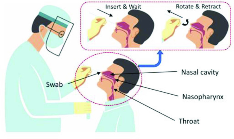
In the present study, we aim to develop a low-cost, easy-to-assemble robot with small footprint to assist NP swab collections. The NP swab collection involves inserting a specifically manufactured swab into the patient’s nasal cavity [8]. The head of the patient is expected to be tilted back (at approximate 70°) so the nasal passage becomes straight and accessible. As illustrated in Figure 1, the swab is inserted through the nostril parallel to the palate, and to the nasopharynx until resistance forces are identified. The swab is then left in place for several seconds for secretion absorptions and been rotationally retracted from the nasal cavity slowly. In this article, we aim to present the design concept, the implementation method, the simulation study, and the preliminary phantom and animal tests of the robot.
Fig. 1.
Diagram showing the nasopharyngeal (NP) swab collection procedure.
II. Design and Implementation of the Robot
A. Design Concepts
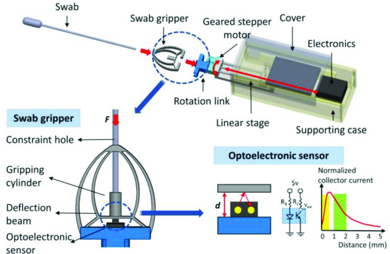
The proposed robot includes an active 2-degree of freedom (DOF) end-effector (Figure 2) for actuating the swab and a generic 6-DOF passive arm for the global positioning. Within the supporting case, a leadscrew driven linear stage actuated by a stepper motor was mounted. A geared stepper motor is attached to the front end of the linear stage to control the following rotation link. As illustrated in Figure 2, a specially designed swab gripper is attached to the rotation link with its extruded structure tightly fitted into the grove of the rotation link. The swab can be assembled to the swab gripper with its shaft constrained by the constraint hole and held by the gripping cylinder of the swab gripper.
Fig. 2.
Schematic illustration of the proposed 2-DOF active end-effector with each component and the mechanism of the force sensing swab gripper shown.
The proposed individual structures allow easy attaching and detaching operations between the swab and the swab gripper that can be performed by either the patient or the on-site health professional, making the collection conveniently and both components recyclable. The overall size of the 2-DOF end-effector is 150(L)
 (W)
(W)
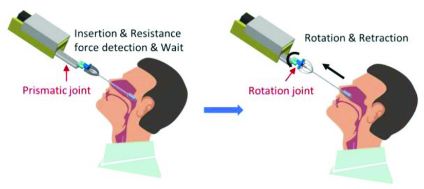
 (D) mm. The movements of the 2-DOF robotic end-effector is shown in Figure 3 with the motions of the prismatic and the rotation joints demonstrated.
Fig. 3.
Movements of the proposed 2-DOF robotic end-effector during the procedure of NP swab collection.
The structure of the swab gripper was designed to also work as a single-axis force sensor based on the principle of compliant mechanism (CM). The compression force experienced by the swab when it is in contact with the nasal cavity would result in the largest vertical displacement segment of the structure at the center of the deflection beam. As shown in Figure 2, the displacement is detected by an optoelectronic sensor (QRE1113, Fairchild Semiconductor, California, the United States) which consists of a LED to generate infrared (IR) light and a photo-transistor to receive the reflected light. The measurement circuit is embedded into a breakout board (SparkFun Electronics, Colorado, the United States) to detect the output voltage, which varies depending on the amount of IR light reflected to the sensor with changes of the distance between the sensor and the deflection beam. Two parts of the characteristic curve (as illustrated in Figure 2) show linear relationships between the measured distance and the output current. To guarantee a high linearity and sensitivity, the yellow area (measured distance in between 0 to 0.50 mm) in Figure 2 was used in this study. The selected sensor has been proved in our previous studies to be able to achieve large output voltage variations without using an amplifier and demonstrates low level of noises [9], [10]. The overall size of the swab gripper is 38(L)
 (W)
(W)
 (D) mm.
B. Hardware and Software Implementation
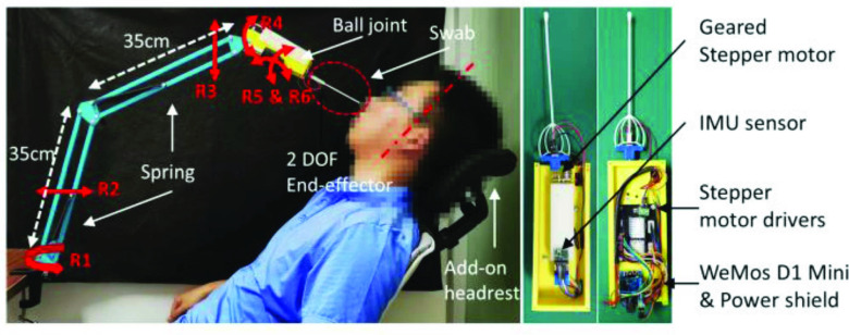
In this research, we employed a 6-DOF passive arm for global positioning and insertion angle adjustments. The passive arm has a global revolute joint (R1), two parallel mechanisms to adjust backwards-forwards and up-down movements (R2 and R3), and a tilting joint (R4) working together with a ball joint (R5 & R6) to fine-tune the angulation of the end-effector, i.e., the insertion angle of the swab. The setup of the 6-DOF passive arm and the 2-DOF active end-effector is shown in Figure 4.
Fig. 4.
Implementation of the proposed robot with its passive arm, active end-effector, add-on headrest, and the embedded electronics shown. The photo was taken only for illustrational purpose to show the expected clinical setup of the NP swab collection procedure.
The setup is to demonstrate the expected clinical scenery for the NP swab collection procedure when using the robot. The passive arm is clamped to the table with the active end-effector attached. An inertial measurement unit (IMU, DT-06, Shenzhen Doctors of Intelligence & Technology Co., Ltd., Shenzhen, China) could be embedded into the end-effector to measure the tilting angle. The add-on headrest has a tilting joint that can be manually adjusted. The combined used of the headrest and the IMU sensor would help to align the angle of the patient’s head and the initial insertion angle of the robot, at approximate 70°.
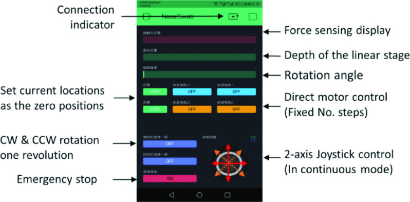
Additionally, a microcontroller (MCU) WeMos D1 mini with its power shield (core chip based on ESP8266, Espressif Systems, Shanghai, China) and two stepper motor drivers (DRV8825, Texas Instruments, Dallas, US) were utilized in the design. The electronics setup is shown in Figure 4. The whole system is powered by a regular 9V-3A power supply which can be directly plug into the power shield. With the WiFi function of the MCU, we developed a mobile phone-based simple user interface (UI) using the Blynk software (Blynk ver. 2.27.17, Android app) to remotely control the stepper motors and display the sensor’s reading. Joysticks, buttons, and level displays were included into the UI with their functions illustrated in Figure 5. Specifically, with the 2-axis joystick actuated diagonally, the swab can be translated and rotated simultaneously, in both directions of each axis to meet the clinical needs as explained in Figure 1.
Fig. 5.
Screenshot of the robot control software developed in Blynk.
The proposed active end-effector was mainly made from 3D printing using Polylactic (PLA) acid and the swab gripper was 3D printed using Polypropylene (PP) material. PLA is the widely used rigid printing material while PP is a semi-rigid flexible material with excellent fatigue resistance. The manufacturing cost of the system is listed in the Table I, with a total cost price of 400 RMB (~55 USD).
TABLE I. Cost Price Summary of the Proposed Robot.
| Components | Cost (RMB) |
|---|---|
| Lead-screw driven linear stage | 32 |
| Geared stepper motor for the rotation link | 45 |
| 3D printed supporting case, covers, and rotation link | 120 |
| 3D printed swab gripper | 18 |
| DRV8825 stepper motor drivers and breakout board | 44 |
| WeMos D1 mini and its power shield | 26 |
| QRE1113 optoelectronic sensor | 10 |
| 6-DOF passive arm and two clamps | 40 |
| Add-on headrest with clamp | 45 |
| Regular 9V-3A power supply | 20 |
| Total costs | 400 |
C. Safety Features
1). Motor Current Limiting and the Maximum Payload:
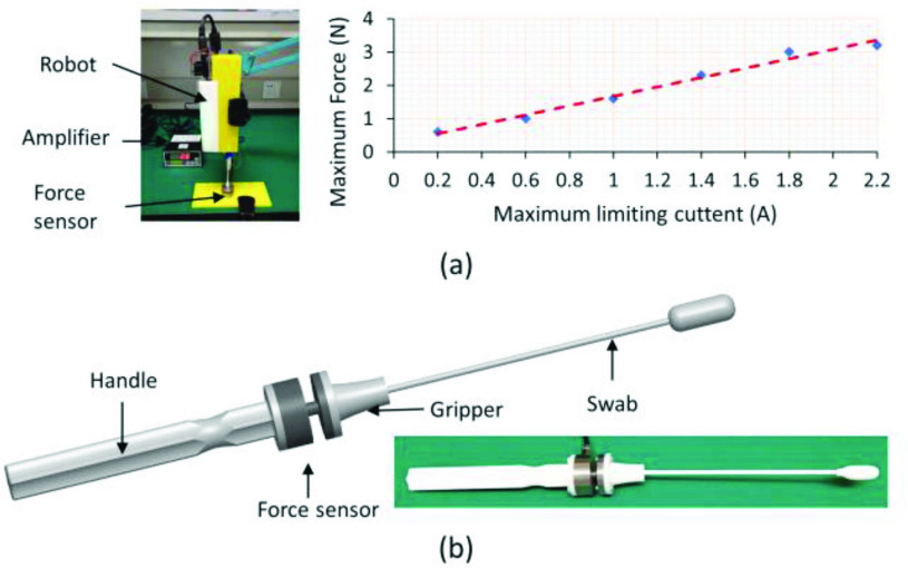
The DRV8825 stepper motor driver used in this study provides an active current limiting method: each full-bridge is controlled by a fixed off-time PWM current control circuit that limits the load current to a desired value. The maximum value of current limiting can be adjusted by setting the reference pin and the motor’s maximum torque is proportional to ampere-turns. This feature limits the maximum allowable force when the swab is in contact with the patient. Test results shown in Figure 6(a) were obtained by adjusting the current limiting setting from 0.2A to the maximum allowable value, 2.2A, of the stepper motor driver in the linear axis and measuring the corresponding maximum forces generated by the linear stage before the stepper motor slips using a commercial force sensor (JHBM-H3, JNSensor, Anhui, China). A regular daily-used shorter swab with wooden shaft was employed to avoid the buckling effects. The experimental setup is shown in Figure 6(a). To decide the value of the maximum current setting, a separate swab holder was designed and 3D printed to integrate with the commercial force sensor (Figure 6(b)). This swab holder allows for the measurement of the maximum force generated during the manually controlled NP swab collection procedure and was tested with a phantom and pig noses (test facilities shown in Figure 9). The maximum force found during the simulation procedure was found to be at the magnitude of 2.50N. Based on the manual experimental results, the maximum payload of the robot was set to 3.00N with some additional allowances. The maximum current setting, in real use, can be further adjusted in an easy way once the in-vivo experiments using the manually controlled swab holder are conducted.
Fig. 6.
(a) Setup for the current-force measurement experiment and the test results; (b) manually controlled tool for the maximum force measurements.
Fig. 9.
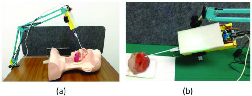
Experimental setups for (a) the phantom and (b) the pig nose tests.
2). Software Settings:
The software settings for safety include a watchdog between the microcontroller and the Blynk software which continually monitors the connection by checking periodically refreshed signals and various software logics to ensure that motor actuation works in conjunction with the force sensors. The WiFi connection between the robot and the control interface is also monitored by the Blynk software based on its default built-in function. Communication failures would be highlighted in the UI to inform the operator.
3). Intrinsic Features:
In addition to above mentioned features, the weight of the 2-DOF end-effector with all the electronics included is only 0.23kg and the weight of the 6-DOF passive arm is 0.31kg. This lightweight design intrinsically reduces the risks when using the robot because the patient can easily move the robot away by pushing the passive arm.
III. Finite Element Analysis of the Swab Gripper
Finite Element (FE) models of the swab gripper and the swab were developed in ANSYS mechanical APDL (ver. 18.2) using geometric input of IGES file that was created by SOLIDWORKS (ver. 2018). The model is to analyze the displacement performances of the deflection beam of the swab gripper when the swab is subjected to external forces. To justify the design, the expected ranges and magnitudes of the displacements should meet the selected linear range of the optoelectronic sensor. In this study, Young’s modulus of 1.70 GPa and Poisson’s ratio of 0.43 were used for the swab gripper based on the information provided by the 3D printing manufacturer. Half model was considered as the whole configuration is symmetric about its central plane. Both parts were meshed using quadratic tetrahedral elements (ANSYS element type: SOLID186). Mix u-p element formulation method was chosen to avoid volumetric locking phenomenon given that the selected material has a Poisson’s ratio of 0.43 which is close to that of an incompressible material (
 ). The swab gripper was meshed using a total number of 32859 elements yielding a total of 55894 nodes and the swab has 4615 elements and 10027 nodes (Figure 7(a)). Contacts between the swab and the constraint hole was modelled as frictionless using Augmented Lagrange algorithm and the contact between the swab and the deflection beam was considered as fully bonded. The boundary conditions were added to constrain the movement of the gripper in Y and Z-axes. 2.50N were applied to the distal end of the swab in seven sub steps as this was the maximum expected force when the swab is in the nasal cavity.
Fig. 7.
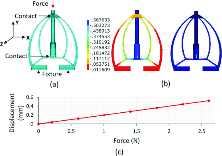
FE modeling of the swab gripper when subjected to external forces: (a) the mesh results with the force, contacts, and the boundary conditions shown, (b) the displacement results under 2.50N, and (c) the force-displacement relationship with the forces applied from 0 to 2.50N.
The swab has a thin long shaft and is subjected to buckling under increasing load. However, as this only happens in a limited range and the swab is constrained by the nasal cavity, the deformations do not cause the collapse and will continue to transfer the load. In this study, we focused on the load analysis. An example color coded displacement profile in the vertical direction and the comparison between undeformed and deformed shapes under 2.50N are shown in Figure 7(b), as the results of the FEA. It can be observed that the maximum displacement occurs at the center point of the deflection beam, resulting in an approximate 0.50 mm deformation. The force-displacement curve is shown in Figure 7(c).
IV. Preliminary Experimental Results
A. Force Calibration
Force calibration was performed using the commercial force sensor. The setup is the same as the previous experiment (Figure 6(a)). The linear stage was actuated slowly to generate the target contact forces (from 0 to 2.50N, 0.50N interval) and the according measured output voltages from the optoelectronic sensor were recorded. The loading (blue line) and unloading (black line) curves are shown in Figure 8, where the elastic hysteresis can be observed. As the current application does not require high accuracy when measuring the force, the average values of the measured output voltage for generating the same amounts of force during the loading and unloading phases were used for the second order polynomial curve fitting and the relationship (red line) between the force values, F, and the voltage V was: V = − 0.1184F2+ 1.4074F + 0.2588. Using the red line as the calibration result, the error of the measured samples is 0.24 ± 0.16V (mean ± standard deviation). The calibration result was programmed into the MCU with running average implemented to smooth out the values from the sensor. To further analyze the performances, the measured voltages were set as inputs and the predicted forces were calculated based on the calibration results. The predicted forces were then compared with the real generated forces and the root-mean-square error (RMSE) was found to be 0.27N.
Fig. 8.
Measurement and processed results of the force calibration experiment.
B. Phantom and Animal Experiments
To validate the performance of the robot and understand the required force for the NP swab sampling procedure, a commercial nasopharynx phantom (Simon Co., Shanghai, China) and three pig noses (from a food supplier, no ethics required) were utilized, as shown in Figure 9. The phantom has realistic shapes and anatomical structures of the human nose although the silicone material’s properties are different to human tissues. The pig noses were obtained from freshly slaughtered pigs (preserved in an ice bag and delivered two days later). Although the anatomical structures of pig nose are different to human nose and the pig noses were cut from the head thereby having shorter lengths, the tissue’s mechanical properties are likely to be close to human.
In both experiments, the insertion angles of the swab were set with the swab parallel to the palate. The phantom is stably positioned on the bench while the pig noses required manual supports to remain stable. The robot was actuated from the mobile app with the insertion first and then the retraction combining with the rotation. For each test, the insertion-retraction procedure was repeated for six times.
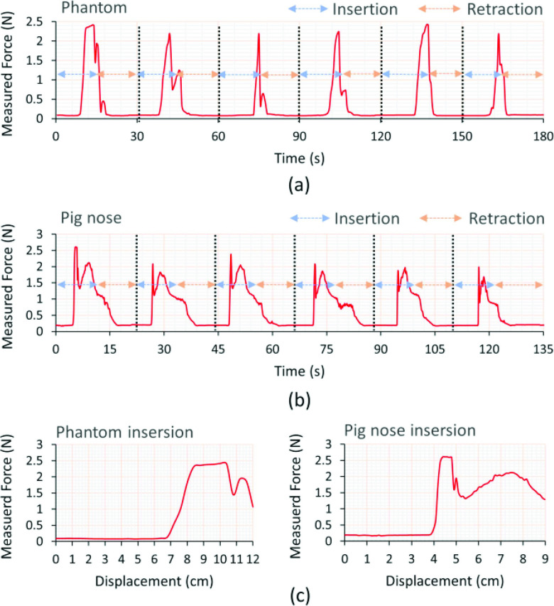
Upon successful completions of both the phantom and the pig nose experiments with the initial insertion axis aligned and the required motions completed, the measured forces versus time for the phantom and an example measurement for the pig nose are shown in Figure 10(a) and Figure 10(b). By extracting the data of the insertion-retraction procedures, the average force was found to be 0.35± 0.58N (mean ± standard deviation) and 0.68 ± 0.64N while the maximum force was 2.43 and 2.61N for the phantom and pig noses, respectively. The maximum identified forces were within the payload of the robot and the detectable range of the customized sensor.
Fig. 10.
Results of force measurements: (a) time versus force using the phantom; (b) time versus force using a pig nose; (c) typical force-displacement curves during the insertion process for the phantom and the pig nose.
As can be seen from Figure 10, the force tends to follow a similar trend in each iteration and reach a peak at the similar magnitude when tested with the phantom and the pig nose. Variations between the two tests are noted, which aroused from differences in anatomical structures of the two test facilities and the initial insertion angles during the two experiments. The peaks were aroused from the contacts between the swab and the nasopharynx for the phantom and the contacts between the swab and turbinates for the pig noses. Additionally, typical force-displacement curves during the swab insertion process for the phantom and the pig nose are also shown in Fig. 10(c) based on the recorded motor steps, which reflect the swab insertion depths in the nasal cavities. The motor was actuated with constant speed during the procedure.
C. Summary
Based on the design introduced in Section II and the preliminary test results analyzed in Sections IV-A and IV-B, the features of the proposed robot were summarized in Table II.
TABLE II. Important Features of the Proposed Robot.
| Components | Important Features | |
|---|---|---|
| Passive arm | DOFs | 6 |
| Joint type | Revolute (R1–R4), Ball (R5 & R6) | |
| Linkage length | 35 cm (Upper and lower) | |
| Weight | 0.31kg | |
| Active end-effector | DOFs | 2 |
| Joint type | Prismatic, Revolute | |
| Dimensions | 150(L)
 (W) (W)
 (D) mm (D) mm |
|
| Weight | 0.23kg | |
| Expected payload | 0–2.50N | |
| Max. payload | 3.00N | |
| Power | 9V-3A | |
| Force-sensing gripper | DOF | 1 |
| Dimensions | 38(L)
 (W) (W)
 (D) mm (D) mm |
|
| Designed range | 0–2.50N | |
| Material | Polypropylene | |
| Calibration error | 0.27N (RMSE) | |
V. Discussions and Conclusion
This article introduces a low-cost miniature robot to assist NP sampling. The robot can be made easily using 3D printing technique together with other easy-to-find commonly used components on the market. The robot is intended to be used in a simple way by assembling different pieces together and controlling from a mobile app. The costs for developing the robot can be further reduced if manufactured in large numbers (estimated to be less than 30 USD). The payload of the robot, when controlling a swab with a long thin shaft, is strictly limited by using small motors. Above the threshold, the motor would slip. To guarantee the safe use, active current limiting, watchdog with periodical response checking were implemented, in addition to the intrinsic features of the robot.
The robot also has a detachable swab gripper which incorporates the force sensing capability based on a simple CM and a low-cost optoelectronic sensor. This piece can be easily assembled to and removed from the robot, making it possible for the suspected patient to do self-assembly and disassembly pre and post being tested. The main detect range of 0–2.50N of the sensing gripper was justified using the FE analysis. The calibration result indicated that the displacement range (0–0.50mm) of the deflection beam meets the prediction of the FE model and falls into the expected linear range of the optoelectronic sensor. The sensor’s design concept was specifically for this low-cost application. Similar concepts of the low-cost 3D printable force sensor using optoelectronic sensors were also found in several related studies [10]–[12].
Using the current available resources, we have tested this robot with a commercial nasopharynx phantom and three pig noses. The successful working of the robot in terms of the required motions was verified and the amounts of forces during the procedure have been preliminarily quantified, in conjunction with the study using a manually controlled tool with a commercial force sensor to measure the maximum forces and decide the maximum current setting of the robot. Based on the current evidence, it is concluded that the measured forces were below the payload of the robot, within the detectable range of the sensing gripper, and has the similar trends and ranges when tested using different facilities.
The initial insertion angle of the robot can be set to be parallel to the palate using the passive arm with supports from visual inspection or IMU sensor, and this ensures the swab go into the lower nasal passages of the phantom and pig noses although both are static objects. Considering the possible motions induced by real patients, additional active DOFs, as replacements of the current passive joints R5 and R6 (pitch and yaw motions) can be added to the robot design to allow further flexibility, although this will increase complexity and cost of the robot. Therefore, the necessity for doing this would need to be further investigated by our future in-vivo tests. The present study was limited to experiments on simulation phantom and pig noses, although both cannot fully represent the real nasal cavity of human. Our next focus will be pursuing ethical approval for in-vivo tests, improving the current force sensor design, modelling the contact between swab tip and soft tissue, and evaluating the effectiveness and robustness of the robot via large-scale tests.
Funding Statement
This work was supported in part by the Institute of Automation, Chinese Academy of Sciences, and in part by the National Natural Science Foundation of China under Grant 62003339 and Grant 82000878.
Contributor Information
Shuangyi Wang, Email: shuangyi.wang@ia.ac.cn.
Kehao Wang, Email: kehaowang@buaa.edu.cn.
Ruijie Tang, Email: ruijie.tang@ia.ac.cn.
Jingzhe Qiao, Email: qiaojz@yeah.net.
Hongbin Liu, Email: hongbin.liu@kcl.ac.uk.
Zeng-Guang Hou, Email: zengguang.hou@ia.ac.cn.
References
- [1].“Laboratory testing for coronavirus disease 2019 (COVID-19) in suspected human cases: Interim guidance,” document WHO/COVID-19/laboratory/2020.4, World Health Org., Geneva, Switzerland, Mar. 2020. [Google Scholar]
- [2].Wang X.et al. , “Comparison of nasopharyngeal and oropharyngeal swabs for SARS-CoV-2 detection in 353 patients received tests with both specimens simultaneously,” Int. J. Infect. Dis., vol. 94, pp. 107–109, May 2020. [Online]. Available: https://doi.org/10.1016/j.ijid.2020.04.023 [DOI] [PMC free article] [PubMed] [Google Scholar]
- [3].Yang Y.et al. (Feb. 2020). Evaluating the Accuracy of Different Respiratory Specimens in the Laboratory Diagnosis and Monitoring the Viral Shedding of 2019-nCoV Infections. [Online]. Available: https://doi.org/10.1101/2020.02.11.20021493 [Google Scholar]
- [4].Carver K. and Jones N., Comparative Accuracy of Oropharyngeal and Nasopharyngeal Swabs for Diagnosis of COVID-19, Centre for Evidence-Based Medicine (CEBM), Nuffield Dept. Primary Care Health Sci., Univ. Oxford, Oxford, U.K., Mar. 2020. Accessed: May 24, 2020. [Online]. Available: https://www.cebm.net/covid-19/comparative-accuracy-of-oropharyngeal-and-nasopharyngeal-swabs-fordiagnosis-of-covid-19/ [Google Scholar]
- [5].Interim Guidelines for Collecting, Handling, and Testing Clinical Specimens for COVID-19, Dept. Health Human Services, Centers Dis. Control Prevent., Atlanta, GA, USA, May 2020. [Google Scholar]
- [6].Yang G.-Z.et al. , “Combating COVID-19—The role of robotics in managing public health and infectious diseases,” Sci. Robot., vol. 5, no. 40, Mar. 2020, Art. no. eabb5589. [Online]. Available: https://doi.org/10.1126/scirobotics.abb5589 [DOI] [PubMed] [Google Scholar]
- [7].Wang Q., China Develops Intelligent Robots for Throat Swab Sampling of Coronavirus Tests, Global Times, Beijing, China, Mar. 2020. Accessed: May 24, 2020. [Online]. Available: https://www.globaltimes.cn/content/1182175.shtml [Google Scholar]
- [8].Marty F. M., Chen K., and Verrill K. A., “How to Obtain a nasopharyngeal swab specimen,” New England J. Med., vol. 382, p. e76, Apr. 2020. [Online]. Available: https://doi.org/10.1056/nejmvcm2010260 [DOI] [PubMed] [Google Scholar]
- [9].Noh Y.et al. , “A 2-piece six-axis force/torque sensor capable of measuring loads applied to tools of complex shapes,” in Proc. IEEE/RSJ IROS, Macau, China, 2019, pp. 7976–7981. [Online]. Available: https://doi.org/10.1109/IROS40897.2019.8967947 [Google Scholar]
- [10].Noh Y., Han S., Gawenda P., Li W., Sareh S., and Rhode K., “A contact force sensor based on s-shaped beams and optoelectronic sensors for flexible manipulators for minimally invasive surgery (MIS),” IEEE Sensors J., vol. 20, no. 7, pp. 3487–3495, Apr. 2020. [Online]. Available: https://doi.org/10.1109/JSEN.2019.2945163 [Google Scholar]
- [11].Hendrich N., Wasserfall F. and Zhang J., “3D printed low-cost force-torque sensors,” IEEE Access, vol. 8, pp. 140569–140585, 2020. [Online]. Available: https://doi.org/10.1109/ACCESS.2020.3007565 [Google Scholar]
- [12].Kesner S. B. and Howe R. D., “Design principles for rapid prototyping forces sensors using 3-D printing,” IEEE/ASME Trans. Mechatronics, vol. 16, no. 5, pp. 866–870, Oct. 2011. [Online]. Available: https://doi.org/10.1109/TMECH.2011.2160353 [DOI] [PMC free article] [PubMed] [Google Scholar]


