

Abstract
A lipid nanoparticle (LNP) formulation is a state-of-the-art delivery system for genetic drugs such as DNA, mRNA, and siRNA, which is successfully applied to COVID-19 vaccines and gains tremendous interest in therapeutic applications. Despite its importance, a molecular-level understanding of the LNP structures and dynamics is still lacking, which makes rational LNP design almost impossible. In this work, we present an extension of CHARMM-GUI Membrane Builder to model and simulate all-atom LNPs with various (ionizable) cationic lipids and PEGylated lipids (PEG-lipids). These new lipid types can be mixed with any existing lipid types with or without a biomolecule of interest, and the generated systems can be simulated using various molecular dynamics engines. As a first illustration, we considered model LNP membranes with DLin-KC2-DMA (KC2) or DLin-MC3-DMA (MC3) without PEG-lipids. The results from these model membranes are consistent with those from the two previous studies albeit with mild accumulation of neutral MC3 in the bilayer center. To demonstrate Membrane Builder’s capability of building a realistic LNP patch, we generated KC2- or MC3-containing LNP membranes with high concentrations of cholesterol and ionizable cationic lipids together with 2 mol% PEG-lipids. We observe that PEG-chains are flexible, which can be more preferentially extended laterally in the presence of cationic lipids due to the attractive interactions between their head groups and PEG oxygen. The presence of PEG-lipids also relaxes the lateral packing in LNP membranes, and the area compressibility modulus (KA) of LNP membranes with cationic lipids fit into typical KA of fluid-phase membranes. Interestingly, the interactions between PEG oxygen and head group of ionizable cationic lipids induce a negative curvature. We hope that this LNP capability in Membrane Builder can be useful to better characterize various LNPs with or without genetic drugs for rational LNP design.
Graphical Abstract

INTRODUCTION
A lipid nanoparticle (LNP) formulation represents a viable delivery system of genetic drugs such as DNA, mRNA, and siRNA for expressing a beneficial protein, silencing a pathological gene, or editing defective genes to treat various diseases, including cancer, hereditary disorders, and viral infections.1,2 A key advance in LNP formulations for effective delivery of genetic drugs to the cytoplasm of target cells has been identification and incorporation of optimized ionizable cationic lipids (Figure 1) with apparent pKa values around 6.5,3 such as dilinoleyl-methyl-4-dimethylaminobutyrate (DLin-MC3-DMA or MC3)3 or dilinoleyl-4-dimethylaminoethyl-[1,3]-dioxolane (DLin-KC2-DMA or KC2).4 In popular ethanol-loading LNP formulations, these cationic lipids whose main role is entrapment of nucleic acid polymers at low pH (~4) are mixed with so-called helper lipids such as cholesterol (CHOL), phospholipids, and PEGylated lipids (in short, PEG-lipids).5 Clearly, LNP-mRNA formulations have become mankind’s hope for COVID-19 vaccines.6
Figure 1.
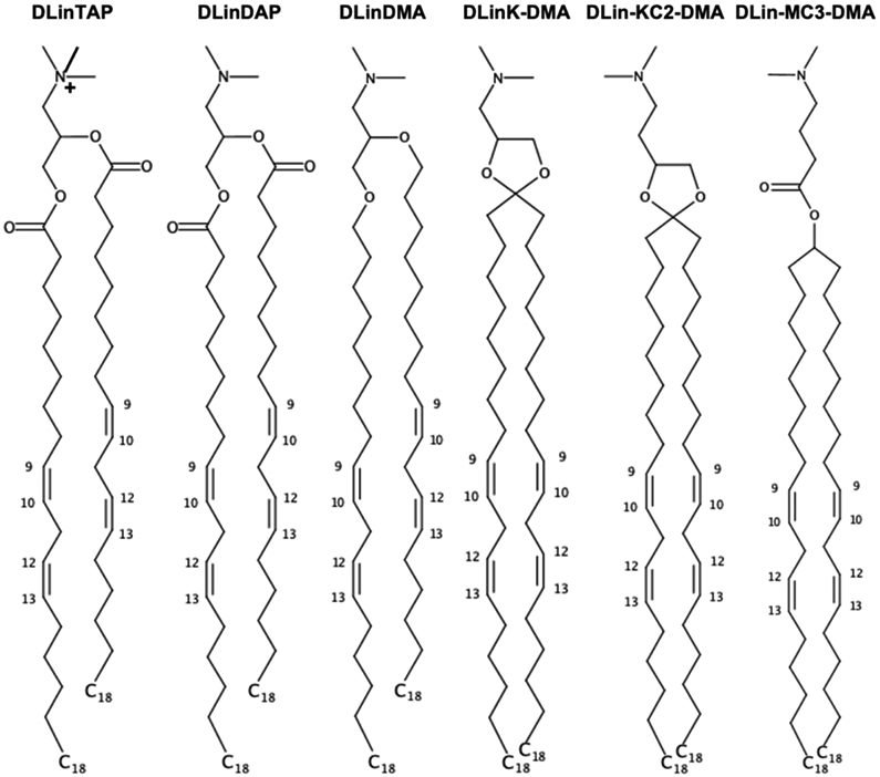
Chemical structures of selected (ionizable) cationic lipids available in Membrane Builder. 1,2-dilineoyl-3-trimethylammonium propane (DLinTAP), 1,2-dilinoleoyl-3-dimethylammonium propane (DLinDAP), 1,2-dilinoleyloxy-3-N,N-dimethylaminopropane (DLinDMA), 1,2-dilinoleyloxy-keto-N,N-dimethyl-3-aminopropane (DLinK-DMA or KC1), 1,2-dilinoleyl-4-dimethylaminoethyl-[1,3]-dioxolane (DLin-KC2-DMA or KC2), and dilinoleylmethyl-4-dimethylaminobutyrate (DLin-MC3-DMA or Mc3).
A molecular-level understanding of the LNP structures and dynamics resulting from delicate interactions among constituent lipids and genetic drugs could provide insight into rational LNP design. Surprisingly, to the best of our knowledge, there are not many all-atom modeling and simulation studies of these complex LNPs or their patches, probably due to difficulties in building such LNP systems with constituent lipids including various ionizable cationic lipids; n.b., all-atom models and simulations are also necessary to develop coarse-grained models for larger systems and longer simulations.7,8 Ramezanpour et al performed all-atom molecular dynamics (MD) simulations of neutral and cationic KC2 in palmitoyl-oleoyl-phosphatidylcholine (POPC) bilayers with or without CHOL.9 The main observation was that neutral KC2s at 10, 20, 30 mol% segregated at the bilayer center, whereas cationic KC2 head groups stayed at the bilayer-water interface. More recently, Ermilova and Swenson performed all-atom MD simulations of neutral MC3 in dioleoyl-phosphatidylcholine (DOPC) or dioleoyl-phosphatidylethanolamine (DOPE) bilayers.10 The main observation was that neutral MC3 head groups at 5 and 15 mol% positioned at the DOPE bilayer-water interface due to strong interactions between DOPE head groups and MC3 head groups and tails, whereas there are no such interactions between MC3 and DOPC. Note that these systems are relatively simple in that LNP formulations generally contain very high concentrations of CHOL and ionizable cationic lipids together with 1-5 mol% PEG-lipids.1,2
This work represents an important extension of CHARMM-GUI Membrane Builder11,12 to model and simulate all-atom LNPs with various (ionizable) cationic lipids and PEG-lipids. We have added 55 (ionizable) cationic lipids with 6 head groups of neutral and cationic forms and 5 tails, as well as PEG-lipids with any number of PEG units and with 20 PE-based and 20 diacylglycerol (DAG)-based tails. These new lipid types can be mixed with any existing lipid types with or without a biomolecule of interest, and the generated MD systems can be simulated using various programs, such as CHARMM,13 GROMACS,14 NAMD,15 LAMMPS,16 AMBER,17 GENESIS,18 OpenMM,19 and Desmond.20 As a first illustration, we have built and simulated all systems of the aforementioned two simulation studies.9,10 In addition, to demonstrate Membrane Builder’s capability to build a realistic LNP patch, we built and simulated KC2- or MC3-containing LNP membranes with high concentration of CHOL (47 mol%) and ionizable cationic lipids (40 mol%) together with 2 mol% PEG-lipids.
METHODS
Membrane Builder implementation
For LNPs, Membrane Builder supports 6 cationic head groups (TAP, DAP, DMA, KC1, KC2, and MC3 in Figure 1) with 5 lipid tails (dimyristoyl (14:0 / 14:0), dipalmitoyl (16:0 / 16:0), dioleoyl (18:1 / 18:1), distearoyl (18:0 / 18:0), and dilinoleoyl (18:2 / 18:2) in Figure 2a). Except TAP, both neutral and cationic head group forms are available; e.g., DLKC2 is a neutral form and DLCK2H is a cationic form. Thus, the combination of head groups and tails yields a total of 55 (ionizable) cationic lipid types. A surface area of 60 Å2 is assigned to each (ionizable) cationic lipid as a tentative value and one can change it for their specific system building purpose. As shown in Figure 2a, one can control the number of lipids in each leaflet using ratios or exact numbers.
Figure 2.

Illustrative snapshots of lipid selection in Membrane Builder for LNPs. (a) Two categories showing (ionizable) cationic lipids and PEG-lipids. Only cationic lipids with dilinoleoyl (18:2 /18:2) tails are shown, although dimyristoyl (14:0 /14:0), dipalmitoyl (16:0 /16:0), dioleoyl (18:1 /18:1), and distearoyl (18:0 /18:0) tails are available for all head group types. Except TAP, both neutral and cationic head group forms are available; e.g., DLKC2 is a neutral form and DLCK2H is a cationic form. For PEG-lipids, one can click “PEGA” to select a lipid type and a tail with the options shown in (b) where DMG-PEG 2000 is constructed based on diacylglycerol (DAG) with dimyristoyl tail and 45 PEG units. Note that only 6 acyl tails are shown in (b) among 20 available tails. (c) Chemical structures of PE- and DAG-based PEG-lipids with n numbers of PEG units (d) An initial conformation of DMG-PEG 2000 that is used for the replacement method. The lipid tail and PEG part are represented by gray and red, respectively. Hydrogen atoms are omitted for clarity.
For PEG-lipids, we followed the workflow used for glycolipid and lipopolysaccharide structure generation in CHARMM-GUI.21 In this workflow, to define a PEG-lipid, one can click “PEGA” (in Figure 2a) to select a lipid type and a tail with the options shown in Figure 2b. Currently, Membrane Builder supports PE-based and DAG-based PEG-lipids (Figure 2c) with 20 different acyl tails. Figure 2b shows how to build DMG-PEG 2000 that is denoted as PEG[45] in Figure 2a. One can add various PEG-lipids with different lipid types, tails, and numbers of PEG units by clicking “Add PEG” in Figure 2a. Similar to other lipid types, one can control the number of lipids in each leaflet using ratios or exact numbers.
Unlike (ionizable) cationic lipids for which we can pre-generate a conformational library of 2,000 structures for the replacement method,22,23 it is impossible to prepare such a conformational library for each PEG-lipid molecule because lipid types, tails, and numbers of PEG units can be varied depending on user selection. Therefore, an additional step was introduced to generate a structure for each user-specified PEG lipid, and the generated structure is then used to replace the lipid-like pseudo spheres in the replacement step. PEG-lipids have very long flexible PEG-chains, and these chains can cause severe steric crashes with the neighboring PEG or lipid molecules during the system generation. In addition, an extended structure of DMG-PEG 2000 (with 45 PEG units) is about 190 Å long along the membrane normal (i.e., the Z axis), which requires an unnecessarily large system size. To avoid these problems, each PEG structure is generated to have a π-helical conformation along the Z axis. Then, additional procedures are introduced to relax the lipid head and tail portions with the PEG structure fixed in a π-helical conformation by performing a simulation with planar and cylindrical restraints; the former is to place the head group and terminal tail atoms in appropriate positions along the Z axis, and the latter is to make the entire PEG-lipid cylindrical along the Z axis. Figure 2d shows an initial structure of DMG-PEG 2000 whose length is about 60 Å. Note that the building process is fast and does not depend on the number of PEG units.
Simulation systems and details
As a first illustration of our building protocol in Membrane Builder, we built and simulated the systems studies by Ramezanpour et al9 (Case 1 in Table 1) and Ermilova and Swenson10 using POPC and POPE instead of DOPC and DOPE (Case 2) to use the same lipid tails as in Case 1. Then, to further illustrate the capability of Membrane Builder, we built and simulated more realistic LNPs using KC2 (Case 3) and MC3 (Case 4). Here, we consider low and high pHs apart from pKa of KC2 and MC3, so each system has either a neutral or cationic form. All membrane systems are symmetric (i.e., the same compositions in both leaflets) and their membrane area is about 140 Å x 140 Å in the XY plane. Each system was neutralized with 150 mM NaCl (with counterions for KC2H and MC3H) using TIP3P water model.24,25 All (ionizable) cationic lipids and PEG molecules are based on the CHARMM36 lipid force field26 and the CGenFF.27 The parameters of PEG model were validated by reproducing the structural and bulk properties of PEG melts and PEG in water, which were prepared using Polymer Builder28 in CHARMM-GUI (see S1. Validation of PEG model in Supporting Information (SI) and Figure S1).
Table 1.
Simulation System information.
| Case 1 | KC2 | KC2H | POPC | CHOL | XYZ (Å3) | #Na / #Cl | #atoms | |
|---|---|---|---|---|---|---|---|---|
| KC2-PC90a | 30 | 270 | 142 x 142 x 85 | 70 / 70 | 159,980 | |||
| KC2-PC80b | 59 | 236 | 140 x 140 x 85 | 67 / 67 | 155,769 | |||
| KC2-PC70c | 90 | 210 | 140 x 140 x 85 | 67 / 67 | 156,536 | |||
| KC2-PC-CHd | 114 | 95 | 171 | 142 x 142 x 85 | 73 / 73 | 160,822 | ||
| KC2H-PC90a | 30 | 270 | 142 x 142 x 85 | 70 / 130 | ||||
| KC2H-PC80b | 59 | 236 | 140 x 140 x 85 | 67 / 185 | 155,594 | |||
| KC2H-PC70c | 90 | 210 | 140 x 140 x 85 | 67 / 247 | 156,728 | |||
| KC2H-PC-CHd | 114 | 95 | 171 | 142 x 142 x 85 | 72 / 300 | 161,210 | ||
| Case 2 | MC3 | MC3H | POPC | POPE | XYZ (Å3) | #Na / #Cl | #atoms | |
| MC3-PC95e | 15 | 285 | 143 x 143 x 85 | 70 / 70 | 160,652 | |||
| MC3-PC85f | 45 | 255 | 142 x 142 x 85 | 69 / 69 | 158,871 | |||
| MC3-PE95e | 17 | 323 | 141 x 141 x 85 | 69 / 69 | 164,977 | |||
| MC3-PE85f | 51 | 289 | 142 x 142 x 85 | 69 / 69 | 164,845 | |||
| MC3H-PC95e | 15 | 285 | 143 x 143 x 85 | 70 / 100 | 160,604 | |||
| MC3H-PC85f | 45 | 255 | 142 x 142 x 85 | 69 / 159 | 159,090 | |||
| MC3H-PE95e | 17 | 323 | 141 x 141 x 85 | 69 / 103 | 164,961 | |||
| MC3H-PE85f | 51 | 289 | 142 x 142 x 85 | 69 / 171 | 164,953 | |||
| Case 3 | KC2 | KC2H | DSPC | CHOL | PEGLi | XYZ (Å3) | #Na / #Cl | #atoms |
| KC2-LNPg | 160 | 44 | 188 | 8 | 143 x 143 x 160 | 205 / 205 | 278,886 | |
| KC2H-LNPg | 160 | 44 | 188 | 8 | 143 x 143 x 156 | 196 / 516 | 297,466 | |
| KC2-DS-CHh | 160 | 52 | 188 | 143 x 143 x 85 | 72 / 72 | 164,192 | ||
| KC2H-DS-CHh | 160 | 52 | 188 | 143 x 143 x 85 | 72 / 392 | 164,349 | ||
| Case 4 | MC3 | MC3H | DSPC | CHOL | PEGLi | XYZ (Å3) | #Na / #Cl | #atoms |
| MC3-LNPg | 160 | 44 | 188 | 8 | 143 x 143 x 141 | 169 / 169 | 246,003 | |
| MC3H-LNPg | 160 | 44 | 188 | 8 | 143 x 143 x 145 | 176 / 496 | 250,233 | |
| MC3-DS-CHh | 160 | 52 | 188 | 143 x 143 x 85 | 72 / 72 | 163,730 | ||
| MC3H-DS-CHh | 160 | 52 | 188 | 143 x 143 x 85 | 72 / 392 | 164,580 |
KC2 (or KC2H) : POPC = 1 : 9.
KC2 (or KC2H) : POPC = 2 : 8.
KC2 (or KC2H) : POPC = 3 : 7.
KC2 (or KC2H) : POPC : CHOL = 30 : 25 : 45.
MC3 (or MC3H) : POPC (or POPE) = 5 : 95.
MC3 (or MC3H) : POPC (or POPE) = 15 : 85.
KC2 (or KC2H or MC3 or MC3H) : DSPC : CHOL : PEGL = 40 : 11 : 47 : 2.
KC2 (or KC2H or MC3 or MC3H) : DSPC : CHOL = 40 : 13 : 47. iDMG-PEG 2000.
DMG-PEG 2000.
All simulations were performed using OpenMM19 with inputs generated by CHARMM-GUI.29 Following Membrane Builder’s default six-step equilibration protocol,22,23 NVT (constant particle number, volume, and temperature) dynamics was first applied with a 1-femtosecond (fs) time step for 250 picoseconds (ps). Subsequently, the NPT (constant particle number, pressure, and temperature) ensemble was applied with a 1-fs time step (for 125 ps) and with a 2-fs time step (for 1.5 nanoseconds (ns)). During the equilibration, positional and dihedral restraint potentials were applied to lipid and water molecules, and their force constants were gradually reduced. A production run was performed for 2 microseconds (μs) (for KC2-LNP, KC2-DS-CH, MC3-LNP, and MC3-DS-CH in Table 1) or 1.5 μs (for all other systems) with a 4-fs time step using the hydrogen mass repartitioning technique30,31 without any restraint potential; see Figure S3 in SI for the time series of the membrane area of each system. The SHAKE algorithm was applied to the bonds containing hydrogen atoms.32 The van der Waals interactions were cut off at 12 Å with a force-switching function between 10 and 12 Å,33 and the electrostatic interactions were calculated by the particle-mesh Ewald method.34 The temperature (at 310 K) and the pressure (at 1 bar) were controlled by Langevin dynamics with a friction coefficient of 1 ps−1 and a semi-isotropic Monte Carlo barostat, respectively.35,36 Figure 3 shows system images for KC2-PC-CH, MC3-PE85, and MC3-LNP.
Figure 3.

Snapshots of (a) final KC2-PC-CH system, (b) final MC3-PE85 system, (c) initially relaxed MC3-LNP system, and (d) final MC3-lNp system. Phospholipids (POPC, POPE, and DSPC), CHOL, and ionizable cationic lipids (KC2 and MC3) are shown in sticks. Each component is shown in different color: phospholipids in white, CHOL in yellow, KC2 and MC3 in ice-blue, PEG-lipid tail in grey, and PEG-chain in red. For clarity, water and ions are omitted and only heavy atoms are shown. The full name of each lipid type is given in the main text. The scale bar represents 20 Å.
Analysis
The last 600-ns trajectories from each simulation were used for analysis. For each frame in the trajectories, the bilayer was centered so that its Z-center was located at Z = 0. From the time series of each system size, its XY-area (A) was calculated (Figure S3). The lateral packing of bilayers was analyzed by calculating the area compressibility modulus (KA) and deuterium order parameters (SCD). KA is defined as KA = kBT ⟨A⟩ / ⟨δA2⟩, where kB is the Boltzmann constant, T is temperature, and <A> and <δA2> are the mean area and its mean square fluctuation, respectively. SCD are defined as
| (1) |
where θ is the angle between a C-H bond vector and the membrane normal, and the bracket represents the time and ensemble average. The bilayer thickness (dB) was defined as the distance between the average Z-positions of P atoms in two leaflets. The distributions of components (phospholipid, ionizable lipid, CHOL, PEG-lipids, ions, and water) along the membrane normal were analyzed by calculating their number density distribution, based on our observations that the bilayers were planar without buckling and undulation.
The torque density of monolayer () is the first moment of the lateral pressure profile, p(Z) = pT(Z) − pN(Z), where pT(Z) = [pxx(Z)+pyy(Z)]/2 and pN(Z) = pzz(Z) = pN are the tangential and normal components of pressure tensors to the membrane surface (see S2. Lateral pressure profile and torque density in SI). To calculate p(Z), the velocity (and associated coordinate) trajectories were generated from the restart files for the last 600 ns, which were saved every 0.1 ns. Two in-house python classes VELFile and VELReporter were used for velocity trajectories, which were modified from DCDFile and DCDReporter for generation of coordinate trajectories in OpenMM. From the (recentered coordinate and velocity) trajectories, p(Z) was calculated using an in-house version of CHARMM, where Harasima contour of slab geometry37 was employed for calculation of pT(z). Because pN(Z) cannot be correctly estimated by Harasima contour,38 with an assumption of a tensionless bilayer, ʃ dZ [pT(Z) − pN] = 0, pN was calculated by pN = ʃ dZ pT(Z)/Lz, where Lz is the Z-dimension of the system.
The PEG conformation was analyzed by the end-to-end distance (⟨h2⟩1/2), its X-, Y-, Z-components (⟨hx2⟩1/2, ⟨hy2⟩1/2, ⟨hz2⟩1/2), and its thickness (dPEG) for which PEG oxygens were chosen; dPEG is defined as the average of ZMAX − ZMIN of PEG oxygens. In addition, the PEG-chain behavior was analyzed by the fraction of PEG-chains involved in inter-chain interactions and the number of PEG units per chain interacting with phospholipids and CHOLs. Two PEG-chains are defined to be in contact if the minimum distance between heavy atom pairs in these chains is less than 4.5 Å. The contact between a PEG unit in a given chain and the membrane is defined by the same distance criterion. The radius of gyration (Rg) of PEG chains were also analyzed for the comparison with that of free PEG in water (Figure S1b), where heavy atoms in PEG chains were chosen.
RESULTS AND DISCUSSION
Illustration 1: Case 1 and Case 2
Our ionizable lipid models and system building are first illustrated by comparing our results with those from Ramezanpour et al9 (Case 1 in Table 1) and Ermilova and Swenson10 (Case 2). Consistent with Ramezanpour et al, neutral KC2 molecules accumulate in the bilayer center, whereas cationic head groups in KC2H stay in the bilayer-water interface (Figures 4, S4a, and S5a). The extent of accumulation increases with KC2 concentration, which also increases the membrane thickness (Figure 5a). In the presence of 45 mol% CHOL (KC2-PO-CH), the accumulation of KC2 is further promoted, which is consistent with the reduced size of LNP at higher CHOL concentration39 due to the condensing effect of CHOL.40-43 Also, CHOLs reside in the lipid monolayers, consistent with the previous studies.9,44
Figure 4.

Density distributions of (a) neutral and (b) cationic DMA head groups. The profiles were calculated over three blocks from the last 600-ns trajectories. The error bars are the standard errors over the three blocks and they are too small to be seen clearly.
Figure 5.

Bilayer properties: (a) membrane thickness (dB), (b) area compressibility modulus (KA), and (c) torque density (). The system names are given at the bottom of each column. Data for systems with neutral KC2 and MC3 lipids are shown in green bars and those for systems with cationic KC2H and MC3H lipids are shown in red bars. The averages were calculated over three 200-ns blocks from the last 600-ns data and the error bars represent the standard errors over the three blocks. These results are also summarized in Table S1 in SI.
Observed POPC order parameters (SCD in Eq. 1) in binary bilayers (without CHOL) are also consistent with Ramezanpour et al9 (at T = 313 K) in that SCD are not sensitive to KC2 or KC2H concentrations (Figure S6a). SCD of KC2’s all tail carbons remain low and are not sensitive to KC2 concentration, indicating that KC2 are randomly oriented in the bilayer center. KC2H’s SCD are larger in the upper half of the tail, consistent with the fact that the cationic head groups stay in the bilayer-water interface. Due to the presence of two cis double bonds (Figure 1), KC2H’s SCD become smaller and comparable to those of KC2 in the lower half of its tail.
In the presence of 45% CHOL, POPC’s SCD become significantly higher than the bilayers without CHOL, which can be attributed to the condensing effect of CHOL.40-43 The increase in POPC’s SCD is less pronounced in KC2H-DS-CH (compared to those in KC2-DS-CH), indicating that repulsive interactions between cationic KC2H molecules reduce CHOL condensing effects. Expectedly, KC2’s SCD are not changed (as KC2 molecules randomly accumulate in the bilayer center), while KC2H SCD are significantly increased with 45% CHOL.
The above behavior of SCD is well reflected in the calculated area compressibility modulus (KA) (Figure 5b). KA is not sensitive to KC2 concentration in bilayers without CHOL, and KA shows slight increase at higher KC2 concentration. The opposing forces between cationic KC2H-KC2H repulsive interactions and CHOL condensing effects are also clearly shown in the resulting much less-increased KA of KC2H-DS-CH compared to that of KC2-DS-CH. The observed SCD and KA are also consistent with the results from a recent simulation study of archaeal membranes,45 where concentration of menaquinone (accumulated in the bilayer center) does not significantly alter KA and SCD of the archaeal bilayers.
Although the extent of accumulation is less significant compared to KC2, neutral MC3 molecules also accumulate in the bilayer center, while MC3H head groups stay in the bilayer water-interface (Figures 4, S4b, and S5b). The extents of MC3 accumulation in MC3/POPC binary bilayers are less pronounced than that of neutral KC2 in KC2/POPC binary bilayers, whereas the MC3 accumulation at 15 mol% MC3 in MC3/POPE bilayer (MC3-PE85) is comparable to KC2 accumulation in KC2/POPC bilayers (in between those in KC2-PC90 and KC2-PC80). The observed less pronounced accumulation of MC3 than KC2 can be attributed to MC3’s structure, where carbonyl oxygen atoms in MC3 head group can interact with the PE head group or glycerol backbone in PC/PE, which can hinder MC3 accumulation in the bilayer center (Ermilova and Swenson10 and Figure 1)
The accumulation of MC3 was not observed in the previous study of Ermilova and Swenson10 with MC3/DOPC and MC3/DOPE binary bilayers. We attribute the observed MC3 accumulation in Case 2 to the difference in the force fields between our work and theirs. The more pronounced accumulation of MC3 in MC3/POPE bilayers than in MC3/POPC bilayers can also be attributed to a negative spontaneous curvature of POPE and a smaller spontaneous curvature of POPC,46 which could enable POPE monolayers to better accommodate domains of neutral MC3 in the bilayer center.
POPE’S SCD are slightly higher than POPC’s SCD (Figure S6b), which is consistent with the findings from Ermilova and Swenson10 in that the carbonyl oxygen atoms in MC3 can form additional hydrogen bonds with PE amine hydrogen atoms. Similar to Case 1, phospholipids’ SCD are not sensitive to MC3 or MC3H concentration. SCD of MC3 and MC3H behave similarly to phospholipids’ SCD except low MC3’s SCD in MC3-PE85 (due to MC3 aggregation in the bilayer center). Consistent with SCD, KA are not sensitive to MC3 and MC3H concentration, and KA from binary bilayers with POPE are slightly larger than those from binary bilayers with POPC.
Illustration 2: Case 3 and Case 4
As a second illustration, we now focus on more realistic LNP membranes with or without PEG-lipids. Consistent with Case 1 and Case 2, KC2 and MC3 accumulate in the bilayer center, and KC2H and MC3H head groups stay in the bilayer-water interface (Figures 4, 6, and S7). Due to accumulated KC2 and MC3, the membrane thickness increases significantly compared to the mixed bilayers with KC2H or MC3H (Figure 7a).
Figure 6.

Final snapshots of (a) Case 3 and (b) Case 4 systems. Each system name is given on top of each column showing the side and top views. The color code is the same as in Figure 3.
Figure 7.

Density profiles of ionizable lipids, PEG-chains, and Cl− ions along the membrane normal (i.e., the Z axis) for (a) KC2H-LNP and (b) MC3H-LNP. Cl− densities are scaled up by a factor of 2 for easier comparison between panels. The profiles were calculated over three 200-ns blocks from the last 600-ns trajectories. The error bars are the standard errors over the three blocks and they are too small to be seen clearly. Each component is shown in different colors: nitrogen in ionizable lipids (magenta), oxygen in PEG-chains (cyan), and Cl− ions (brown).
As expected, the surface areas are comparable between KC2- and MC3-containing bilayers as KC2s and MC3s are segregated to the bilayer center (Figure S3c). The surface areas of KC2H-containing bilayers are consistently larger than those of MC3H-containing bilayers. This can be attributed to the difference in head group structures between KC2H and MC3H (Figure 1), where a bulkier five membered ring in KC2H compared to the carbonyl group in MC3H makes lipid packing less tight. This also results in a higher Cl− density due to higher surface charge density in MC3H-containing bilayers (Figures 4, 7, and S7).
Lateral lipid packing in Case 3 and Case 4 is consistent with Case 1 and Case 2. SCD of DSPC and PEG-lipid are larger for mixed bilayers with neutral KC2/MC3 than those with KC2H/MC3H (Figure S8) due to the counteraction between cationic KC2H/MC3H repulsive interactions and CHOL’s condensing effect. SCD of KC2/MC3 remain low due to their accumulation at the bilayer center and those of KC2H/MC3H are significantly higher. The calculated KA are consistent with the observed SCD, where KA of KC2H/MC3H-containing membranes are significantly smaller than those of KC2/MC3-containing membranes (Figure 5b).
The presence of PEG-lipids slightly reduces SCD of DSPC and KC2H, which can be attributed to shorter myristoyl (14:0) tails in PEG-lipids that induce less order than stearoyl (18:0) tails in DSPC. The decrease in KA with PEG-lipids is consistent with the observed behavior of DSPC’s SCD. With PEG-lipids, KA of LNPs with cationic lipids (KC2H or MC3H) fit into typical KA of fluid-phase membranes.46,47
Effects of ionizable cationic lipids on PEG-membrane interactions
PEG-chains in our simulations are flexible (Movies S1-4 in SI). The radius of gyration of PEG-chains (Rg) in LNP membranes with cationic ionizable lipids (14.9 Å for KC2H-LNP and 14.6 Å for MC3H-LNP) are in excellent agreement with the predicted Rg of the corresponding free PEG (whose molecular weight is the same to that of the PEG-chain in our LNP membranes) in a good solvent, water, from dilute solution simulations (Figure S1b). Rg of the PEG chain decreases slightly in LNP membranes with neutral ionizable lipids (13.8 Å for both KC2-LNP and MC3-LNP). Considering the uncertainties in Rg (3.0–3.4 Å) (Figure S1b), the PEG-chains in our LNP membranes appear to behave similarly to the free PEGs in dilute solutions.
The PEG thickness (dPEG) is comparable or smaller than the end-to-end distance, ⟨h2⟩1/2 (Figure S9), indicating that PEG-chains are in the mushroom conformation regime (expected from low surface density).8,48,49 PEG-chains in KC2-LNP and MC3-LNP frequently make inter-PEG contacts, while those in KC2H-LNP and MC3H-LNP interact more with the membrane (Figure S10).
More frequent inter-PEG contacts in LNPs with KC2 or MC3 than those in LNPs with KC2H or MC3H are consistent with the increased surface PEG-lipid concentration from 2% to ~3.3% due to the accumulation of KC2 and MC3 in the bilayer center. The attractive interactions between cationic KC2H head groups and PEG oxygens are responsible for the observed PEG-membrane interactions, which also makes the PEG conformations extended more preferentially on the membrane surface (Figures 6 and S9).
The interactions between MC3H head groups and PEG oxygen atoms become weaker in MC3H-LNP, due to a higher concentration of Cl− ions near the membrane (Figure 7). As a result, the PEG-membrane contacts become smaller than those in KC2H-LNP (Figure S10b) and the PEG end-to-end distance becomes isotropic (Figure S9b).
Effects of ionizable cationic lipids and PEG-lipids on membrane curvature
Inclusion of ionizable cationic lipids and/or PEG-lipids affects lateral packing of membranes (see above), as well as the membrane curvature. These effects are reflected in the monolayer torque density, (see S2. Lateral pressure profile and torque density in SI). The sign of dictates the direction of applied (bending) torque, and the sign of its change, , between different concentrations of ionizable cationic lipids and/or PEG-lipids indicates the direction of the induced curvature. In this work, we adopt a typical sign convention of the curvature (Figure S2): a monolayer at a positive curvature is convex to the head group side, and vice versa. In this convention, positive between two systems indicates that a positive curvature is induced, and vice versa.
At the lowest KC2/KC2H concentration (10 mol%), are small negative numbers (Figure 5c) close to that of pure POPC bilayer (around −30 cal/mol/Å)46. increases with KC2 concentration, indicating that accumulated KC2 at the bilayer center induces positive curvature to the monolayers. However, are much less sensitive to KC2H concentration, indicating that KC2H do not strongly affect the membrane curvature. This can be attributed to the structurally similar head groups of KC2H to PC of phospholipids, which have small intrinsic curvature.46 For CHOL-containing bilayers, becomes noticeably negative compared to those of CHOL-free bilayers, consistent with the negative curvature induced by CHOL.50
Opposite to the variation in KC2/POPC bilayers, of MC3/POPC binary bilayers becomes more negative at a higher MC3 concentration (Case 2 in Figure 5c), indicating that MC3 induces negative curvature with POPC, which is likely due to the interactions between carbonyl oxygen in MC3 and the glycerol backbone in POPC.10 Opposite to the variation in MC3/POPC, increasing MC3 concentration makes become more positive in MC3/POPE binary bilayer due to the accumulation of MC3 in the bilayer center, rendering the POPE monolayer curvature less negative and thus the entire system becomes more stable. Similarly to KC2H, are not sensitive to MC3H concentration both in MC3H/POPC and MD3H/POPE binary bilayers. Again, this can be attributed to similar head group structures between MC3H and PC.
Effects of PEG-lipids on of KC2-containing bilayers appear to be minimal, as shown by statistically similar between KC2-LNP and KC2-DS-CH. between MC3-LNP and MC3-DS-CH are also similar. These results indicate that the interactions between PEG-lipid and KC2/MC3 are likely to be weak (as KC2/MC3 are located in the bilayer center), and do not appear to affect the membrane curvature.
For KC2H-containing bilayers, the interactions between KC2H and PEG-lipid significantly affect , as shown by noticeably more negative of KC2H-LNP compared to that of KC2H-DS-CH. Such induced negative curvature arises from the attractive interactions between KC2H and PEG oxygen. The same trend is observed between MC3H-LNP and MC3-DS-CH, though the extent of induced negative curvature is smaller, as a higher Cl− ion concentration near the membrane due to higher surface charge density (Figure 7) weakens the attractive interactions between MC3H and PEG oxygen.
Implications to genetic drug delivery
It has been accepted that the incorporation of helper lipids including PEG-lipids in LNPs is required to increase the circulation time, so that LNPs can reach target cells.5 After their uptake to cytoplasm, the cationic lipids and endogenous anionic lipids produce a non-bilayer structure at low pH in the endosome, i.e., below the pKa of ionizable cationic lipids, which results in the disruption of the endosomal membrane and release of genetic drugs into the cytoplasm.1
Prior to the delivery process, PEG-chains need to be detached from LNPs for efficient endocytosis of nanocarriers loaded with genetic drugs. Otherwise, drug activity can be dramatically decreased by reduction of the cellular uptake of LNPs51-53 and accelerated blood clearance after repeated doses of PEGylated liposomes.54,55 The cleavable PEGylation56-58 is one of the approaches that can overcome this issue, i.e., the so-called PEG dilemma.
Our results show that PEG-lipid linkage can be exposed more in KC2H-containing LNPs than MC3H-containing ones (Figures 6, 7, and S9b and Movies S1-4). For efficient cleavage of PEGylation, the linkage between PEG and lipid tails are desired to be exposed to extracellular or intracellular microenvironment, such as temperature, pH, specific enzyme, reductive conditions, etc.59-61 Therefore, our results implicate that one can tune cationic ionizable lipid-PEG interactions to achieve desired cleavage of PEGylation for rational LNP design and optimal drug delivery.
CONCLUSIONS
We have described an important extension of CHARMM-GUI Membrane Builder to model and simulate LNPs with various (ionizable) cationic lipids and PEG-lipids. To illustrate this new feature, we have built and simulated all systems of two previous simulation studies, Ramezanpour et al.9 and Ermilova and Swenson.10 As another more practical illustration to demonstrate Membrane Builder’s capability to build a realistic LNP patch, we built and simulated KC2- and MC3-based LNP membranes with very high cholesterol and ionizable cationic lipids together with 2 mol% PEG-lipids.
In our simulations, cationic lipids (KC2H and MC3H) stay at the bilayer-water interface, and neutral KC2 and MC3 molecules segregate into the bilayer center, though MC3 accumulation is less pronounced. The accumulation of KC2/MC3 does not alter lateral lipid packing, which has been also reported in a recent study of archaeal membranes.45 The results from binary bilayers of KC2/KC2H and POPC are consistent with Ramezanpour et al. The less pronounced MC3 accumulation is consistent with observed MC3 and phospholipid interactions in Ermilova and Swenson. However, MC3 accumulation was not observed in Ermilova and Swenson (binary bilayers of MC3 and DOPC/DOPE), which is attributed to differences in the force fields between our work and theirs.
In our simulations of more realistic LNP patches, we could study the effects of PEG-lipids on the membrane properties, which have not been studied in the previous works of Ramezanpour et al.9 and Ermilova and Swenson.10 PEG-chains are flexible and frequently extended to bulk water. They are extended more preferentially on the membrane surface of LNP membranes with cationic lipids due to the interactions between PEG oxygen and their cationic head groups. The presence of PEG-lipids appears to relax lateral lipid packing in LNP membranes by decreasing KA and SCD of DSPC and cationic lipids (KC2H and MC3H). Interestingly, KA of LNP membranes with cationic lipids (KC2H or MC3H) fit into typical KA of fluid-phase membranes. Our results show that the interactions between PEG oxygen and cationic lipid head groups induce a negative curvature. Our results also show that PEG-cationic ionizable lipid interactions can be tuned for the desired cleavage of PEGylation for optimal drug delivery. However, we note that there could be other important factors for favorable drug delivery that we are not aware of yet. Therefore, it would be an interesting future study to connect our findings to the experimental data for LNP efficacy, which would be useful in modeling and simulation LNPs with encapsulated nucleic acids in different environments.
Supplementary Material
ACKNOWLEDGEMENTS
This study was supported in part by grants from NIH GM138472 and NSF MCB-1810695.
Footnotes
DATA AND SOFTWARE AVAILABILITY
All simulation data are available upon reasonable request. Membrane Builder can be accessed through the following link: https://charmm-gui.org/input/membrane.bilayer.
SUPPORTING INFORMATION
The Supporting Information is available free of charge at https://pubs.acs.org/.
Additional sections for validation of PEG model (S1) and lateral pressure profile and torque density (S2); table showing membrane thickness, area compressibility modulus, and torque density (Table S1), mean square end-to-end distance and radius of gyration of PEG chains (Figure S1), typical monolayer curvature convention (Figure S2), time series of membrane area (Figure S3), final snapshots (Figure S4), density profiles (Figures S5 and S7); SCD order parameters (Figure S6 and S8), end to end distance and thickness of PEG (Figure S9), fraction of PEG-lipid interacting with other PEG-lipids and the number of PEG units per chain interacting with membrane (Figure S10) (PDF)
REFERENCES
- (1).Cullis PR; Hope MJ Lipid Nanoparticle Systems for Enabling Gene Therapies. Mol. Ther 2017, 25, 1467–1475. [DOI] [PMC free article] [PubMed] [Google Scholar]
- (2).Kulkarni JA; Cullis PR; Van Der Meel R Lipid Nanoparticles Enabling Gene Therapies: From Concepts to Clinical Utility. Nucleic Acid Ther. 2018, 28, 146–157. [DOI] [PubMed] [Google Scholar]
- (3).Jayaraman M; Ansell SM; Mui BL; Tam YK; Chen J; Du X; Butler D; Eltepu L; Matsuda S; Narayanannair JK; Rajeev KG; Hafez IM; Akinc A; Maier MA; Tracy MA; Cullis PR; Madden TD; Manoharan M; Hope MJ Maximizing the Potency of SiRNA Lipid Nanoparticles for Hepatic Gene Silencing In Vivo. Angew. Chemie - Int. Ed 2012, 51, 8529–8533. [DOI] [PMC free article] [PubMed] [Google Scholar]
- (4).Semple SC; Akinc A; Chen J; Sandhu AP; Mui BL; Cho CK; Sah DWY; Stebbing D; Crosley EJ; Yaworski E; Hafez IM; Dorkin JR; Qin J; Lam K; Rajeev KG; Wong KF; Jeffs LB; Nechev L; Eisenhardt ML; Jayaraman M; Kazem M; Maier MA; Srinivasulu M; Weinstein MJ; Chen Q; Alvarez R; Barros SA; De S; Klimuk SK; Borland T; Kosovrasti V; Cantley WL; Tam YK; Manoharan M; Ciufolini MA; Tracy MA; De Fougerolles A; MacLachlan I; Cullis PR; Madden TD; Hope MJ Rational Design of Cationic Lipids for SiRNA Delivery. Nat. Biotechnol 2010, 28, 172–176. [DOI] [PubMed] [Google Scholar]
- (5).Evers MJW; Kulkarni JA; van der Meel R; Cullis PR; Vader P; Schiffelers RM State-of-the-Art Design and Rapid-Mixing Production Techniques of Lipid Nanoparticles for Nucleic Acid Delivery. Small Methods 2018, 2, 1700375. [Google Scholar]
- (6).Shin MD; Shukla S; Chung YH; Beiss V; Chan SK; Ortega-Rivera OA; Wirth DM; Chen A; Sack M; Pokorski JK; Steinmetz NF COVID-19 Vaccine Development and a Potential Nanomaterial Path Forward. Nature Nanotechnology. 2020, pp 646–655. [DOI] [PubMed] [Google Scholar]
- (7).Leung AKK; Hafez IM; Baoukina S; Belliveau NM; Zhigaltsev IV; Afshinmanesh E; Tieleman DP; Hansen CL; Hope MJ; Cullis PR Lipid Nanoparticles Containing SiRNA Synthesized by Microfluidic Mixing Exhibit an Electron-Dense Nanostructured Core. J. Phys. Chem. C 2012, 116, 18440–18450. [DOI] [PMC free article] [PubMed] [Google Scholar]
- (8).Lee H; Pastor RW Coarse-Grained Model for PEGylated Lipids: Effect of PEGylation on the Size and Shape of Self-Assembled Structures. J. Phys. Chem. B 2011, 115, 7830–7837. [DOI] [PMC free article] [PubMed] [Google Scholar]
- (9).Ramezanpour M; Schmidt ML; Bodnariuc I; Kulkarni JA; Leung SSW; Cullis PR; Thewalt JL; Tieleman DP Ionizable Amino Lipid Interactions with POPC: Implications for Lipid Nanoparticle Function. Nanoscale 2019, 11, 14141. [DOI] [PubMed] [Google Scholar]
- (10).Ermilova I; Swenson J DOPC: Versus DOPE as a Helper Lipid for Gene-Therapies: Molecular Dynamics Simulations with DLin-MC3-DMA. Phys. Chem. Chem. Phys 2020, 22, 28256–28268. [DOI] [PubMed] [Google Scholar]
- (11).Jo S; Kim T; Iyer VG; Im W CHARMM-GUI: A Web-Based Graphical User Interface for CHARMM. J. Comput. Chem 2008, 29, 1859–1865. [DOI] [PubMed] [Google Scholar]
- (12).Wu EL; Cheng X; Jo S; Rui H; Song KC; Davila-Contreras EM; Qi YF; Lee JM; Monje-Galvan V; Venable RM; Klauda JB; Im W CHARMM-GUI Membrane Builder Toward Realistic Biological Membrane Simulations. J. Comp. Chem 2014, 35, 1997–2004. [DOI] [PMC free article] [PubMed] [Google Scholar]
- (13).Brooks BR; Brooks CL; Mackerell AD; Nilsson L; Petrella RJ; Roux B; Won Y; Archontis G; Bartels C; Boresch S; Caflisch A; Caves L; Cui Q; Dinner AR; Feig M; Fischer S; Gao J; Hodoscek M; Im W; Kuczera K; Lazaridis T; Ma J; Ovchinnikov V; Paci E; Pastor RW; Post CB; Pu JZ; Schaefer M; Tidor B; Venable RM; Woodcock HL; Wu X; Yang W; York DM; Karplus M CHARMM: The Biomolecular Simulation Program. J. Comput. Chem 2009, 30, 1545–1614. [DOI] [PMC free article] [PubMed] [Google Scholar]
- (14).Abraham MJ; Murtola T; Schulz R; Páll S; Smith JC; Hess B; Lindah E Gromacs: High Performance Molecular Simulations through Multi-Level Parallelism from Laptops to Supercomputers. SoftwareX 2015, 1–2, 19–25. [Google Scholar]
- (15).Phillips JC; Braun R; Wang W; Gumbart J; Tajkhorshid E; Villa E; Chipot C; Skeel RD; Kale L; Schulten K Scalable Molecular Dynamics with NAMD. J. Comput. Chem 2005, 26, 1781–1802. [DOI] [PMC free article] [PubMed] [Google Scholar]
- (16).Plimpton S Fast Parallel Algorithms for Short-Range Molecular Dynamics. J. Comput. Phys 1995, 117, 1–19. [Google Scholar]
- (17).Case DA; Cheatham TE; Darden T; Gohlke H; Luo R; Merz KM; Onufriev A; Simmerling C; Wang B; Woods RJ The Amber Biomolecular Simulation Programs. J. Comput. Chem 2005, 26, 1668–1688. [DOI] [PMC free article] [PubMed] [Google Scholar]
- (18).Jung J; Mori T; Kobayashi C; Matsunaga Y; Yoda T; Feig M; Sugita Y GENESIS: A Hybrid-Parallel and Multi-Scale Molecular Dynamics Simulator with Enhanced Sampling Algorithms for Biomolecular and Cellular Simulations. Wiley Interdiscip. Rev. Comput. Mol. Sci 2015, 5, 310–323. [DOI] [PMC free article] [PubMed] [Google Scholar]
- (19).Eastman P; Swails J; Chodera JD; McGibbon RT; Zhao YT; Beauchamp KA; Wang LP; Simmonett AC; Harrigan MP; Stern CD; Wiewiora RP; Brooks BR; Pande VS OpenMM 7: Rapid Development of High Performance Algorithms for Molecular Dynamics. PloS Comput. Biol 2017, 13, e1005659. [DOI] [PMC free article] [PubMed] [Google Scholar]
- (20).Bowers KJ; Chow E; Xu H; Dror RO; Eastwood MP; Gregersen BA; Klepeis JL; Kolossvary I; Moraes MA; Sacerdoti FD; Salmon JK; Shan Y; Shaw DE Scalable Algorithms for Molecular Dynamics Simulations on Commodity Clusters. SC ‘06 Proc. 2006 ACM/IEEE Conf. Supercomput. 2006, 43–43. [Google Scholar]
- (21).Lee J; Patel DS; Ståhle J; Park SJ; Kern NR; Kim S; Lee J; Cheng X; Valvano MA; Holst O; Knirel YA; Qi Y; Jo S; Klauda JB; Widmalm G; Im W CHARMM-GUI Membrane Builder for Complex Biological Membrane Simulations with Glycolipids and Lipoglycans. J. Chem. Theory Comput 2019, 15, 775–786. [DOI] [PubMed] [Google Scholar]
- (22).Jo S; Kim T; Im W Automated Builder and Database of Protein/Membrane Complexes for Molecular Dynamics Simulations. PLoS One 2007, 2, e880. [DOI] [PMC free article] [PubMed] [Google Scholar]
- (23).Jo S; Lim JB; Klauda JB; Im W CHARMM-GUI Membrane Builder for Mixed Bilayers and Its Application to Yeast Membranes. Biophys. J 2009, 97, 50–58. [DOI] [PMC free article] [PubMed] [Google Scholar]
- (24).Jorgensen WL; Chandrasekhar J; Madura JD; Impey RW; Klein ML Comparison of Simple Potential Functions for Simulating Liquid Water. J. Chem. Phys 1983, 79, 926–935. [Google Scholar]
- (25).MacKerell AD; Bashford D; Bellott M; Dunbrack RL; Evanseck JD; Field MJ; Fischer S; Gao J; Guo H; Ha S; Joseph-McCarthy D; Kuchnir L; Kuczera K; Lau FTKK; Mattos C; Michnick S; Ngo T; Nguyen DT; Prodhom B; Reiher WE; Roux B; Schlenkrich M; Smith JC; Stote R; Straub J; Watanabe M; Wiórkiewicz-Kuczera J; Yin D; Karplus M All-Atom Empirical Potential for Molecular Modeling and Dynamics Studies of Proteins. J. Phys. Chem. B 1998, 102, 3586–3616. [DOI] [PubMed] [Google Scholar]
- (26).Klauda JB; Venable RM; Freites JA; O’Connor JW; Tobias DJ; Mondragon-Ramirez C; Vorobyov I; MacKerell AD; Pastor RW Update of the CHARMM All-Atom Additive Force Field for Lipids: Validation on Six Lipid Types. J. Phys. Chem. B 2010, 114, 7830–7843. [DOI] [PMC free article] [PubMed] [Google Scholar]
- (27).Vanommeslaeghe K; Hatcher E; Acharya C; Kundu S; Zhong S; Shim J; Darian E; Guvench O; Lopes P; Vorobyov I; Mackerell AD CHARMM General Force Field: A Force Field for Drug-Like Molecules Compatible with the CHARMM All-Atom Additive Biological Force Fields. J. Comput. Chem 2010, 31, 671–690. [DOI] [PMC free article] [PubMed] [Google Scholar]
- (28).Choi YK; Park SJ; Park S; Kim S; Kern NR; Lee J; Im W CHARMM-GUI Polymer Builder for Modeling and Simulation of Synthetic Polymers. J. Chem. Theory Comput 2021, 17, 2431–2443. [DOI] [PMC free article] [PubMed] [Google Scholar]
- (29).Lee J; Cheng X; Swails JM; Yeom MS; Eastman PK; Lemkul JA; Wei S; Buckner J; Jeong JC; Qi Y; Jo S; Pande VS; Case DA; Brooks CL 3rd; MacKerell AD Jr.; Klauda JB; Im W CHARMM-GUI Input Generator for NAMD, GROMACS, AMBER, OpenMM, and CHARMM/OpenMM Simulations Using the CHARMM36 Additive Force Field. J. Chem. Theory Comput 2016, 12, 405–413. [DOI] [PMC free article] [PubMed] [Google Scholar]
- (30).Hopkins CW; Le Grand S; Walker RC; Roitberg AE Long-Time-Step Molecular Dynamics through Hydrogen Mass Repartitioning. J. Chem. Theory Comput 2015, 11, 1864–1874. [DOI] [PubMed] [Google Scholar]
- (31).Gao Y; Lee J; Smith IPS; Lee H; Kim S; Qi Y; Klauda JB; Widmalm G; Khalid S; Im W CHARMM-GUI Supports Hydrogen Mass Repartitioning and Different Protonation States of Phosphates in Lipopolysaccharides. J. Chem. Inf. Model 2021, 61, 831–839. [DOI] [PMC free article] [PubMed] [Google Scholar]
- (32).Ryckaert J-P; Ciccotti G; Berendsen HJC Numerical Integration of the Cartesian Equations of Motion of a System with Constraints: Molecular Dynamics of n-Alkanes. J. Comput. Phys 1977, 23, 327–341. [Google Scholar]
- (33).Steinbach PJ; Brooks BR New Spherical-Cutoff Methods for Long-Range Forces in Macromolecular Simulation. J. Comput. Chem 1994, 15, 667–683. [Google Scholar]
- (34).Essmann U; Perera L; Berkowitz ML; Darden T; Lee H; Pedersen LG A Smooth Particle Mesh Ewald Method. J. Chem. Phys 1995, 103, 8577–8593. [Google Scholar]
- (35).Chow KH; Ferguson DM Isothermal-Isobaric Molecular Dynamics Simulations with Monte Carlo Volume Sampling. Comput. Phys. Commun 1995, 91, 283–289. [Google Scholar]
- (36).Åqvist J; Wennerström P; Nervall M; Bjelic S; Brandsdal BO Molecular Dynamics Simulations of Water and Biomolecules Wit a Monte Carlo Constant Pressure Algorithm. Chem. Phys. Lett 2004, 384, 288–294. [Google Scholar]
- (37).Harasima A Molecular Theory of Surface Tension. Adv. Chem. Phys 1958, 1, 203–237. [Google Scholar]
- (38).Sonne J; Hansen FY; Peters GH Methodological Problems in Pressure Profile Calculations for Lipid Bilayers. J. Chem. Phys 2005, 122, 124903. [DOI] [PubMed] [Google Scholar]
- (39).Kulkarni JA; Witzigmann D; Leung J; Tam YYC; Cullis PR On the Role of Helper Lipids in Lipid Nanoparticle Formulations of SiRNA. Nanoscale 2019, 11, 21733. [DOI] [PubMed] [Google Scholar]
- (40).Leathes JB Croonian Lectures ON THE RÔLE OF FATS IN VITAL PHENOMENA. Lancet 1925, 205, 853–856. [Google Scholar]
- (41).Demel RA; Van Deenen LLM; Pethica BA MONOLAYER INTERACTIONS OF PHOSPHOLIPIDS AND CHOLESTEROL. BBA - Biomembr. 1967, 135, 11–19. [Google Scholar]
- (42).Stockton GW; Smith ICP, A DEUTERIUM NUCLEAR MAGNETIC RESONANCE STUDY OF THE CONDENSING EFFECT OF CHOLESTEROL ON EGG PHOSPHATIDYLCHOLINE BILAYER MEMBRANES. I. PERDEUTERATED FATTY ACID PROBES. Chem. Phys. Lipids 1976, 17, 251–263. [DOI] [PubMed] [Google Scholar]
- (43).Daly TA; Wang M; Regen SL The Origin of Cholesterol’s Condensing Effect. Langmuir 2011, 27, 2159–2161. [DOI] [PMC free article] [PubMed] [Google Scholar]
- (44).Kulkarni JA; Darjuan MM; Mercer JE; Chen S; Van Der Meel R; Thewalt JL; Tam YYC; Cullis PR On the Formation and Morphology of Lipid Nanoparticles Containing Ionizable Cationic Lipids and SiRNA. ACS Nano 2018, 12, 4787–4795. [DOI] [PubMed] [Google Scholar]
- (45).Feng S; Wang R; Pastor RW; Klauda JB; Im W Location and Conformational Ensemble of Menaquinone and Menaquinol, and Protein–Lipid Modulations in Archaeal Membranes. J. Phys. Chem. B 2021, 125, 4714–4725. [DOI] [PMC free article] [PubMed] [Google Scholar]
- (46).Venable RM; Brown FLH; Pastor RW Mechanical Properties of Lipid Bilayers from Molecular Dynamics Simulation. Chem. Phys. Lipids 2015, 192, 60–74. [DOI] [PMC free article] [PubMed] [Google Scholar]
- (47).Rawicz W; Olbrich KC; McIntosh T; Needham D; Evans E Effect of Chain Length and Unsaturation on Elasticity of Lipid Bilayers. Biophys. J 2000, 79, 328–339. [DOI] [PMC free article] [PubMed] [Google Scholar]
- (48).Suk JS; Xu Q; Kim N; Hanes J; Ensign LM PEGylation as a Strategy for Improving Nanoparticle-Based Drug and Gene Delivery HHS Public Access Graphical Abstract. Adv Drug Deliv Rev 2016, 99, 28–51. [DOI] [PMC free article] [PubMed] [Google Scholar]
- (49).Labouta HI; Gomez-Garcia MJ; Sarsons CD; Nguyen T; Kennard J; Ngo W; Terefe K; Iragorri N; Lai P; Rinker KD; Cramb DT Surface-Grafted Polyethylene Glycol Conformation Impacts the Transport of PEG-Functionalized Liposomes through a Tumour Extracellular Matrix Model. RSC Adv. 2018, 8, 7697–7708. [DOI] [PMC free article] [PubMed] [Google Scholar]
- (50).Kollmitzer B; Heftberger P; Rappolt M; Pabst G Monolayer Spontaneous Curvature of Raft-Forming Membrane Lipids. Soft Matter 2013, 9, 10877–10884. [DOI] [PMC free article] [PubMed] [Google Scholar]
- (51).Song LY; Ahkong QF; Rong Q; Wang Z; Ansell S; Hope MJ; Mui B Characterization of the Inhibitory Effect of PEG-Lipid Conjugates on the Intracellular Delivery of Plasmid and Antisense DNA Mediated by Cationic Lipid Liposomes. Biochim. Biophys. Acta - Biomembr 2002, 1558, 1–13. [DOI] [PubMed] [Google Scholar]
- (52).Hatakeyama H; Akita H; Harashima H The Polyethyleneglycol Dilemma: Advantage and Disadvantage of PEGylation of Liposomes for Systemic Genes and Nucleic Acids Delivery to Tumors. Biological and Pharmaceutical Bulletin. 2013, pp 892–899. [DOI] [PubMed] [Google Scholar]
- (53).Lechanteur A; Furst T; Evrard B; Delvenne P; Hubert P; Piel G PEGylation of Lipoplexes: The Right Balance between Cytotoxicity and SiRNA Effectiveness. Eur. J. Pharm. Sci 2016, 93, 493–503. [DOI] [PubMed] [Google Scholar]
- (54).Xu H; Ye F; Hu M; Yin P; Zhang W; Li Y; Yu X; Deng Y Influence of Phospholipid Types and Animal Models on the Accelerated Blood Clearance Phenomenon of PEGylated Liposomes upon Repeated Injection. Drug Deliv. 2015, 22, 598–607. [DOI] [PubMed] [Google Scholar]
- (55).Kierstead PH; Okochi H; Venditto VJ; Chuong TC; Kivimae S; Fréchet JMJ; Szoka FC The Effect of Polymer Backbone Chemistry on the Induction of the Accelerated Blood Clearance in Polymer Modified Liposomes. J. Control. Release 2015, 213, 1–9. [DOI] [PMC free article] [PubMed] [Google Scholar]
- (56).Kulkarni PS; Haldar MK; Nahire RR; Katti P; Ambre AH; Muhonen WW; Shabb JB; Padi SKR; Singh RK; Borowicz PP; Shrivastava DK; Katti KS; Reindl K; Guo B; Mallik S MMP-9 Responsive PEG Cleavable Nanovesicles for Efficient Delivery of Chemotherapeutics to Pancreatic Cancer. Mol. Pharm 2014, 11, 2390–2399. [DOI] [PMC free article] [PubMed] [Google Scholar]
- (57).Zhao G; Long L; Zhang L; Peng M; Cui T; Wen X; Zhou X; Sun L; Che L Smart PH-Sensitive Nanoassemblies with Cleavable PEGylation for Tumor Targeted Drug Delivery. Sci. Rep 2017, 7, 3383. [DOI] [PMC free article] [PubMed] [Google Scholar]
- (58).Fang Y; Xue J; Gao S; Lu A; Yang D; Jiang H; He Y; Shi K Cleavable PEGylation: A Strategy for Overcoming the “PEG Dilemma” in Efficient Drug Delivery. Drug Deliv. 2017, 24, 22–32. [DOI] [PMC free article] [PubMed] [Google Scholar]
- (59).Sawant RM; Hurley JP; Salmaso S; Kale A; Tolcheva E; Levchenko TS; Torchilin VP “SMART” Drug Delivery Systems: Double-Targeted PH-Responsive Pharmaceutical Nanocarriers. Bioconjug. Chem 2006, 17, 943–949. [DOI] [PMC free article] [PubMed] [Google Scholar]
- (60).Terada T; Iwai M; Kawakami S; Yamashita F; Hashida M Novel PEG-Matrix Metalloproteinase-2 Cleavable Peptide-Lipid Containing Galactosylated Liposomes for Hepatocellular Carcinoma-Selective Targeting. J. Control. Release 2006, 111, 333–342. [DOI] [PubMed] [Google Scholar]
- (61).Koutroumanis KP; Holdich RG; Georgiadou S Synthesis and Micellization of a PH-Sensitive Diblock Copolymer for Drug Delivery. Int. J. Pharm 2013, 455, 5–13. [DOI] [PubMed] [Google Scholar]
Associated Data
This section collects any data citations, data availability statements, or supplementary materials included in this article.