Abstract
Background:
Augmentation of the proximal femur with bone cement (femoroplasty) has been identified as a potential preventive approach to reduce the risk of fracture. Femoroplasty, however, is associated with a risk of thermal damage as well as the leakage of bone cement or blockage of blood supply when large volumes of cement are introduced inside the bone.
Methods:
Six pairs of cadaveric femora were augmented using a newly proposed planning paradigm and an in-house navigation system to control the location and volume of the injected cement. To evaluate the risk of thermal damage, we recorded the peak temperature of bone at three regions of interest as well as the exposure time for temperature rise of 8°C, 10°C, and 12°C in these regions. Augmentation was followed by mechanical testing to failure resembling a sideway fall on the greater trochanter.
Findings:
Results of the fracture tests correlated with those of simulations for the yield load (R2 = 0.77) and showed that femoroplasty can significantly improve the yield load (42%, P<0.001) and yield energy (139%, P=0.062) of the specimens. Meanwhile, temperature recordings of the bone surface showed that the areas close to the greater trochanter will be exposed to more critical temperature rise than the trochanteric crest and femoral neck areas.
Interpretation:
The new planning paradigm offers a more efficient injection strategy with injection volume of 9.1 ml on average. Meanwhile, temperature recordings of bone surfaces suggest that risk of thermal necrosis remains as a concern with femoroplasty using Polymethylmethacrylate.
Keywords: Osteoporotic hip augmentation, PMMA Cement, Finite Element Analysis, Surgical Planning
1. Introduction
Osteoporotic hip fracture rates increase exponentially with age in both men and women (Melton et al., 2001). Because of the aging population in the United States, the annual number of incidents could total 840,000 by the year 2040 (Schneider et al., 1990). The overall 1-year mortality rate for those sustaining a hip fracture has been reported to be as 20–30% (Schnell et al., 2010). Moreover, less than half of the survivors return to their prefracture status with respect to the quality of daily living (Melton et al., 2009). Therefore, an effective approach to reduce the number of incidents is both necessary and significant. While most treatment options offer long-term effects, percutaneous injection of bone cement or femoroplasty could reduce the short-term risk of fractures by enhancing the fracture-related biomechanical properties (i.e., yield load and yield energy) (Beckmann, 2011; Basafa, 2013a; Varga, 2017; Santana Artiles, 2017). In the study of Beckmann et al. (2011), it was shown that the single central augmentation (aligned with the femoral neck axis) utilizing Polymethylmethacrylate (PMMA) as the bone cement results in very effective increase of the fracture energy in the bone. In addition, their study pointed out that bones augmented with double drill holes had a lower fracture strength compared to the single drilled ones.
Although femoroplasty is effective in improving the biomechanical parameters of the bone, it is associated with challenges that need to be addressed before it can be used as a clinical procedure. One of the biggest challenges is the risk of thermal damage as a result of PMMA polymerization. In particular, when the blood supply to the femoral head is interrupted due to cell death, it collapses, a condition clinically defined as the Avascular Necrosis (AVN). Because of this some studies have considered patient-specific models combined with optimization algorithms to further enhance the efficacy of injections (Basafa., 2013a; Santana Artiles, 2017). In the study of Basafa et al. (2013a), injection patterns were determined based on a Bi-directional Evolutionary Structural Optimization (BESO) algorithm and the strain energy was used as the optimization criterion, while in the computational study of Santana Artiles et al. (2017) principal strain values were used as the optimization criterion. These studies had similar results suggesting that areas close to the greater trochanter and superior and inferior aspects of the femoral neck would benefit most from cementation (Basafa, 2013a ; Santana Artiles, 2017). In contrast to patient-specific algorithms that require advanced surgical systems, other studies have proposed generic injection patterns. Fliri et al. (2013) investigated the biomechanical potential of V-shaped injection configurations targeting the superior and inferior femoral neck an in-vitro study and showed that such patterns that result in 124% more energy absorption before fracture. Varga et al. (2017) proposed new injection strategies for femoroplasty based on the principles of bone remodeling and concluded that “compression bridge” injections aligned with the femoral neck axis has the greatest biomechanical efficiency. Although generic injections may be comparable to the patient-specific approaches in some cases, using patient-specific models to plan the injection and estimate the outcomes can help pre-define the surgical steps and reduce the risk of complications. Of note, cement diffusion is highly dependent on the material distribution within the proximal femur. With a generic plan for femoroplasty, a potential blockage of the blood supply may not be identified. In addition, patient-specific femoroplasty can incorporate heat transfer models to estimate the bone temperature and evaluate the risk of thermal necrosis caused by cement polymerization (Farvardin et al., 2018).
In a recent computational study, we introduced a new patient-specific planning paradigm to reduce the volume of injected cement (Farvardin et al., 2019). Through Finite Element (FE) simulations, biomechanical outcomes of injections were compared with those of the generic injections. Results showed that injection recommendations of the new planning paradigm can significantly increase the yield load (79.6%, P < 0.01) and yield energy (199%, P < 0.01) of an osteoporotic femur. The increase was significantly higher than those of generalized injections proposed previously (Beckmann, 2011; Fliri, 2013; Varga, 2017), but requires an experimental validation to evaluate the efficacy of the procedure. Therefore, contributions of this paper include investigating: 1) the biomechanical effectiveness of the newly proposed planning paradigm; and 2) the bone surface temperature rise during cement polymerization through cadaveric experiments.
2. Methods
2.1. Pre-operative planning paradigm
We described the details of the biomechanically guided planning paradigm in a different study (Farvardin et al., 2019). There are two major differences between this planning paradigm and the plan previously developed by Basafa et al. (2014): 1) In the previous generation of the subject-specific plan for femoroplasty, injections were simulated for three different regions of the proximal femur with each region containing several ‘test’ points and the injection that overlapped most with the BESO pattern was selected to determine the drill path (Basafa et al., 2014). In this study, parameters that determine the injection profile are selected through an optimization algorithm and 2) cement injections in the new plan were performed dynamically (i.e., the injection needle is retracted during cementation), while the injection needle was fixed during cementation previously. This improves the overall coverage of the optimal pattern. To summarize, six pairs of fresh cadaveric femur specimens (one male and five females) were obtained from the Maryland State Anatomy Board, Dual Energy X-ray Absorptiometry (DEXA) scanned (Lunar Prodigy Advance, GE Healthcare Lunar, Madison, WI), and cleaned of soft tissue. The specimens were then stored in a freezer (−18 °C) until one day before the augmentation procedure when they were left at room temperature to thaw. A relevant summery of cadavers’ demographics and DEXA scanning results are presented in Table 1. For planning, a Computed Tomography (CT) scan with voxel spacing of 0.5mm was obtained for each of the specimens (Toshiba Aquilion One, Canon Inc., Tochigi, Japan). Following the procedure in (Basafa et al., 2013a), a FE model was created for each bone and the initial yield load was estimated. In this approach, material properties of each element were assigned based on the bone density observed from CT scan performed with a density phantom. From each pair, one femur with the lower initial yield load was selected for augmentation. The new planning paradigm consists of three steps: first, the optimal pattern of bone cement was determined through an FE analysis in which inhomogeneous material properties were assigned to the bone elements based on density values calculated from CT. This was achieved utilizing a modified method of Bi-directional Evolutionary Structural Optimization (BESO) (Basafa & Armand, 2014). In the second phase of planning, a gradient-descent optimization algorithm was used to find the closest match between BESO results and realistic injection blobs of bone cement. The optimization constraints the injection volume such that only one drill hole is required. In addition, the total volume of injection does not exceed 12 ml (Farvardin et al., 2019):
| (1) |
where VBESO is the optimal pattern of PMMA defined by the FE and VInjection consists of 2 or 3 injection blobs in cylindrical shapes with end caps that lie on a single injection path (Fig. 1). In the third step of planning, cement dispersion inside the bone was predicted using a modified method of Smoothed Particle Hydrodynamics (SPH), which uses discrete particles to approximate continuum field quantities. In this modified method of SPH continuous quantities of density field are assumed to be known at some discrete locations (particles) and one can approximate their values in any other given point in the bone by employing the so-called “smoothing kernel” function. As a part of the planning paradigm, we use SPH results to predict the actual yield load of the specimen after augmentation with realistic injection blobs. For this purpose, we first create a porous model of the proximal femur from the CT volume (considering the inhomogeneous permeability of the bone) and remove the tissue particles on the path of a virtual drill (or injection needle). Next, we simulate the injection of bone cement at the rate of 0.1 ml/s and viscosity of 200 Pa.s. on the same path (Basafa et al., 2013b).
Table 1-.
Sample demographics– Neck T-scores and BMD were obtained from DEXA Scanning. The Neck T-scores and BMDs are reported for both the limb to be augmented and the control side.
| Sample | Age | Gender | Neck T-score | Neck BMD (g/cm2) | Condition | ||
|---|---|---|---|---|---|---|---|
| Augmented | Control | Augmented | Control | ||||
| 1 | 89.3 | Female | −3.8 | −2.0 | 0.525 | 0.735 | Osteoporotic |
| 2 | 69.3 | Female | −2.2 | −2.8 | 0.716 | 0.641 | Osteoporotic |
| 3 | 59.4 | Female | −2.2 | −2.0 | 0.714 | 0.738 | Osteopenic |
| 4 | 91.8 | Female | −4.0 | −3.6 | 0.496 | 0.550 | Osteoporotic |
| 5 | 72.8 | Female | −4.3 | −4.2 | 0.468 | 0.480 | Osteoporotic |
| 6 | 68.4 | Male | −2.8 | −2.6 | 0.590 | 0.617 | Osteoporotic |
| Average(±SD) | 75.2(±12.7) | - | −3.2(±0.9) | −2.9(±0.9) | 0.58(±1.0) | 0.63(±10) | - |
Figure 1 –
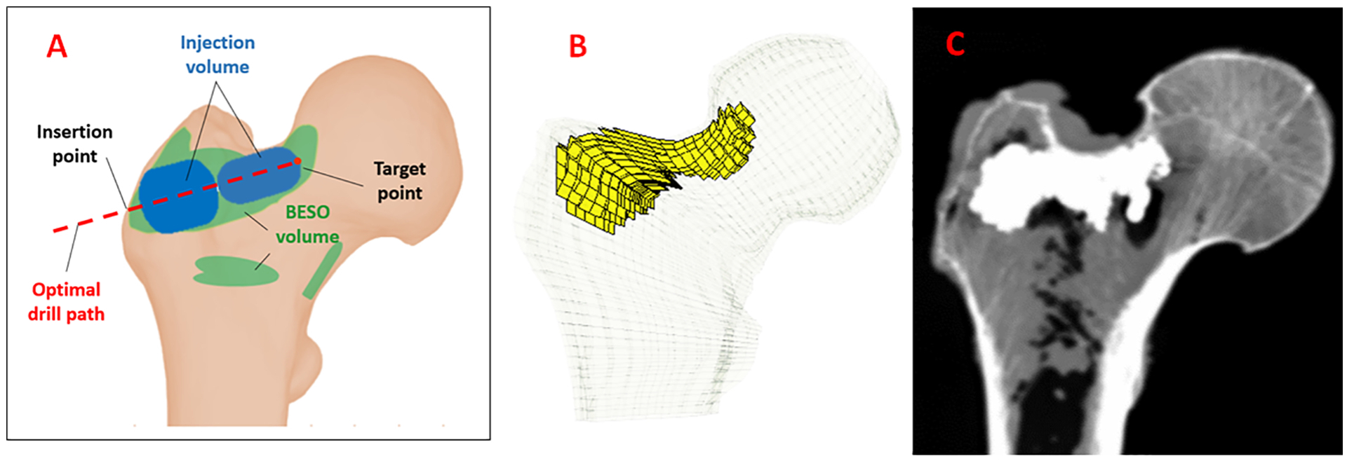
A) Schematic of a typical optimized injection pattern by FE using BESO method (green) and the injection blobs defined by the planning paradigm (Blue), B) FE mesh of the femur specimen with planned pattern of injection C) Example radiograph of the augmented bone (sample 1).
2.2. Navigation system
Prior to each experiment, femora were removed from the freezer and left at room temperature to thaw. This was followed by removing the remaining soft tissue from the femur. For navigation, we used an in-house system developed and validated previously (Otake et al., 2010). Briefly, three landmarks, i.e., center of the head, lateral most point on the greater trochanter, and the protrusion point of the lesser trochanter, were selected on the model of the bone segmented in the Medical Imaging Interaction Toolkit (MITK) (German Cancer Research Center, Heidelberg, Germany) Using a tracked digitizer (Passive Probe, NDI, Waterloo. ON, Canada) and an optical tracker (Polaris, NDI, Waterloo, ON, Canada) these points were identified on the femur specimen. The transformation between these two sets, provided an initial guess for registration. Next, patches of surface points were digitized, and a point cloud-to-surface registration was performed using the Iterative Closest Point (ICP) algorithm (Besl et al., 1992) (Fig. 2c). Bone registration was followed by navigation of a cordless hand drill (DCD760, DeWalt Industrial Tool Co., Baltimore, MD, United States) tracked by a rigid body to drill the injection path defined by the pre-operative plan. The navigation guides the user to the drill path by providing the distance and angle errors of the drilling configuration in real-time.
Figure 2 –
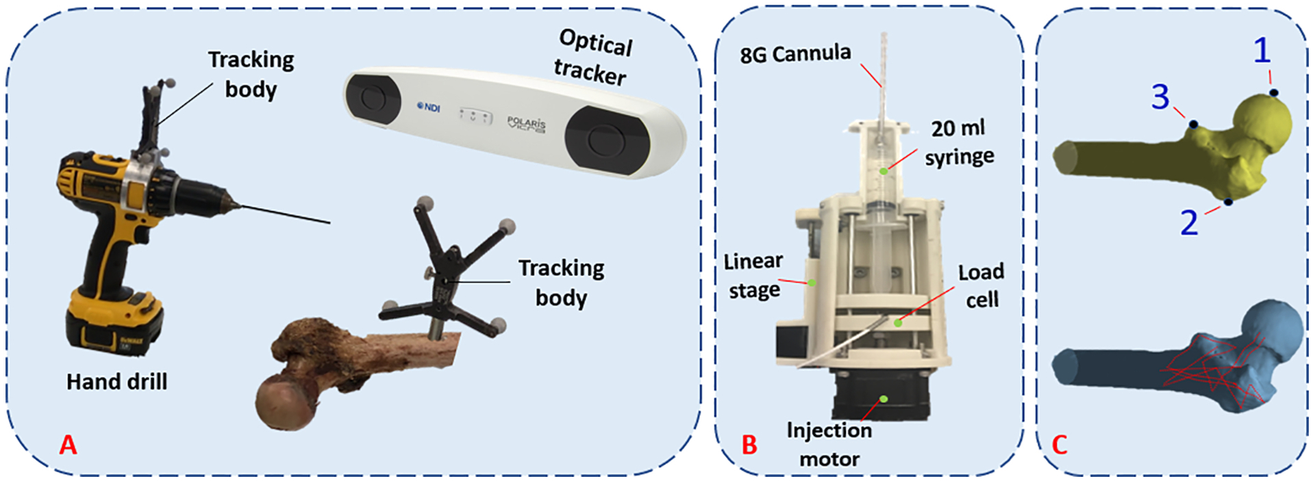
(A) Intra-operative system for drilling navigation, (B) An automatic injection device for bone cement delivery into the planned region, (C) Predetermined points for initial registration (top) and surface points used for ICP registration (bottom).
2.3. Cement Injection and temperature measurement
After drilling, we used a custom designed injection device similar to that of previously developed by Kutzer et al. (2011) for cement delivery. The modified device utilizes a 20 ml syringe. Consequently, 15 g of radiopaque ½ dose Spineplex (Stryker, Kalamazoo, MI, United States) was mixed with 13.5 ml of the monomer liquid for about 60 s. We then filled the syringe with this mixture, attached a 15.2 cm, 8G cannula (Scientific Commodities Inc., Lake Havasu, AZ, United Sates) and placed it in the injection device. Approximately 12 minutes from the start of mixing the powder and liquid, we estimated the viscosity of bone cement by ejecting 0.5 ml of cement at the rate of 0.1 ml/s while measuring and averaging the pressure using a compression load cell (OMEGA Engineering Inc., Stamford, CT, United States). This viscosity estimate, along with previously extracted viscosity-time calibration curves for this cement mix using the same setup, was used to calculate the remaining time before the cement reaches the desired viscosity of 200 Pa.s. At that time, cement was automatically ejected at the controlled rate of 0.1 ml/s while the injection device retracted the cannula from the start of the first injection blob (target point) towards the bone surface.
Note that the retraction rate of the cannula varies for each blob depending on their size (length and radius). Meanwhile, from the start time of the injection, we measured the surface temperature of the bone at one second intervals in three regions, i.e., greater trochanter, trochanteric crest, and femoral neck using previously planted k-type thermocouples (Thermometrics Inc., Northbridge, CA, United States) with probe diameter of 0.6mm. Thermocouples were placed inside 1mm drill holes made on the surface at the depth of 2mm to minimize the effect of room temperature on the measurements. Figure 3 shows the location of the thermocouples with respect to the femur anatomy. These regions were selected based on the location of the main arteries that supply blood to the femoral head (Gautier, 2000; Sevitt, 1965).
Figure 3 –
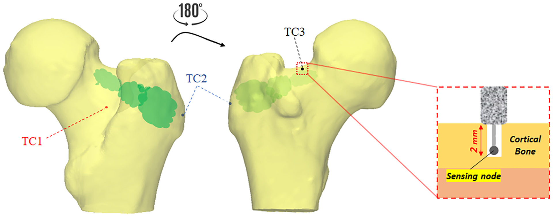
Thermocouple placement for temperature measurements. Note that k-type thermocouples recorded the temperature at one second interval and depth of 2mm from the surface on trochanteric crest (TC1; red), the greater trochanter (TC2; blue), and femoral neck (TC3; black)
2.4. Post-operative mechanical testing and data analysis
Following the plan-based injections, another set of CT scan was obtained. To discover how closely PMMA distributions matches those of pre-operative simulations, we used the technique previously described in (Basafa et al., 2015) to estimate the translational error between their corresponding isosurface. This was followed by mechanical testing to failure in configuration of a fall to the side on the greater trochanter. As shown in Fig. 4, we positioned such that the axis of femur shaft was 10 degrees below a horizontal plan parallel to the MTS table and rotated the femoral shaft 15 degrees internally (Sutter et al., 2010). While the greater trochanter was supported by a dollop of PMMA, the femoral head was pre-loaded to 50N by the MTS machine (Bionix 858 Test System, MTS, Eden Prairie, MN, United States). Next, femoral head was displaced downward at the rate of 100 mm/s until failure (Sutter et al., 2010). For each specimen, the first inflection point of the load-displacement curve was recorded as yield load. In addition, we recorded the maximum load. Yield and maximum energy were defined as the area under force-displacement curve up to yield and maximum load respectively (Basafa et al., 2015). A paired t-test was used to compare the biomechanical outcomes of the augmented and control femora (P < 0.05). In comparison of the biomechanical properties, we have only considered the osteoporotic specimens (Sample #1, 2, 4, 5 and 6).
Figure 4 –
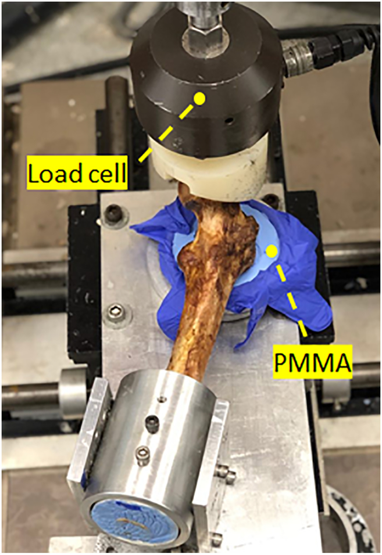
Experimental set-up simulating a fall on the greater trochanter using MTS machine (Bionix 858 Test System, Eden Prairie, Minnesota)
To evaluate the potential risk of thermal damage, we recorded the peak temperature of bone at each of the three regions of interest as well as the exposure time for temperature rise of 8°C, 10°C, and 12°C in these regions (Fig. 3).
3. Results
FE simulations predicted an average yield load of 1866(SD=359)N for the osteoporotic specimens of the control group, while that of their augmented pairs prior to cementation was lower with an average of 1659(SD=453)N (P = 0.039). With some variations, the pre-operative plan recommended injection (drilling) paths that start from the vicinity of the supero-posterior aspect of the greater trochanter and continue towards the superior part of the neck. The algorithm also suggested that a mean of 9.1(SD = 1.2)ml of PMMA injections adequate to increase the yield load of the osteoporotic specimens by an average of 73% (from 1659(SD=453)N to 2877(SD=345)N). Yield load values measured in mechanical testing were found to be linearly correlated with those of simulations (R2 = 0.77) (Fig. 5). The fracture tests revealed that on average, augmented specimens have a 42% larger yield load (1951N vs. 2774N, P <0.001) and 29% larger maximum load (2216N vs. 2853N, P=0.01) compared to those of the control group. Consequently, yield and maximum energy of the augmented pairs were larger by an average of 139% (SD=)(4.4J vs. 10.5J, P =0.062) and 29% (24J vs. 30.9J, P= 0.23) respectively (Table 2). Figures 6 shows the results of fracture tests for the osteoporotic pairs. In most cases, femur fractures of the control group occurred in locations that are clinically defined as the intertrochanteric fractures (Karagas et al., 1996). The fracture locations were slightly different for the augmented pairs depending on the injection location. The osteopenic sample fractured from the inferior part of the femoral head (Fig. 7).
Figure 5 –
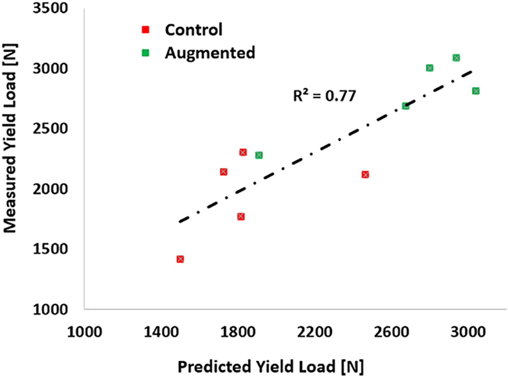
Measured vs. Predicted yield loads. The overall correlation coefficient is 0.77.
Table 2-.
Results of femoroplasty: YL and ML represent the yield load and maximum load in N, respectively, and YE and ME represent the yield energy and maximum energy in Joules, respectively. Moreover, “Pre”, “Plan”, and “Post” represent the FE analysis based on the pre-operative CT, virtual CT created from the plan, and post-operative CT, respectively.
| Control | Augmented | |||||||||||||||
|---|---|---|---|---|---|---|---|---|---|---|---|---|---|---|---|---|
| Simulation | Fracture test | Simulation | Fracture test | |||||||||||||
| Sample # | YL [N] | YL [N] | ML [N] | YE [J] | ME [J] | YL [N] (Pre) | YL [N] (Plan) | YL [N] (Post) | YL [N] | ML [N] | YE [J] | ME [J] | ||||
| 1 | 1500 | 1419 | 1706 | 2.90 | 20.07 | 1350 | 2785 | 1910 | 2282 | 2360 | 8.91 | 19.03 | ||||
| 2 | 1825 | 2302 | 2497 | 3.77 | 26.97 | 1745 | 3330 | 2800 | 3003 | 3142 | 8.96 | 58.26 | ||||
| 4 | 1815 | 1771 | 2253 | 4.22 | 28.72 | 1680 | 2830 | 2675 | 2685 | 2685 | 4.50 | 13.33 | ||||
| 5 | 1725 | 2145 | 2145 | 4.90 | 19.08 | 1170 | 2395 | 2940 | 3087 | 3159 | 22.67 | 39.63 | ||||
| 6 | 2465 | 2116 | 2481 | 6.37 | 25.17 | 2350 | 3045 | 3040 | 2812 | 2920 | 7.48 | 24.19 | ||||
| Mean | 1866 | 1951 | 2216 | 4.43 | 24.00 | 1659 | 2877 | 2673 | 2774 | 2853 | 10.50 | 30.89 | ||||
| SD | 359 | 355 | 322 | 1.3 | 4.2 | 453 | 345 | 448 | 317 | 336 | 7.0 | 18.2 | ||||
Figure 6 –
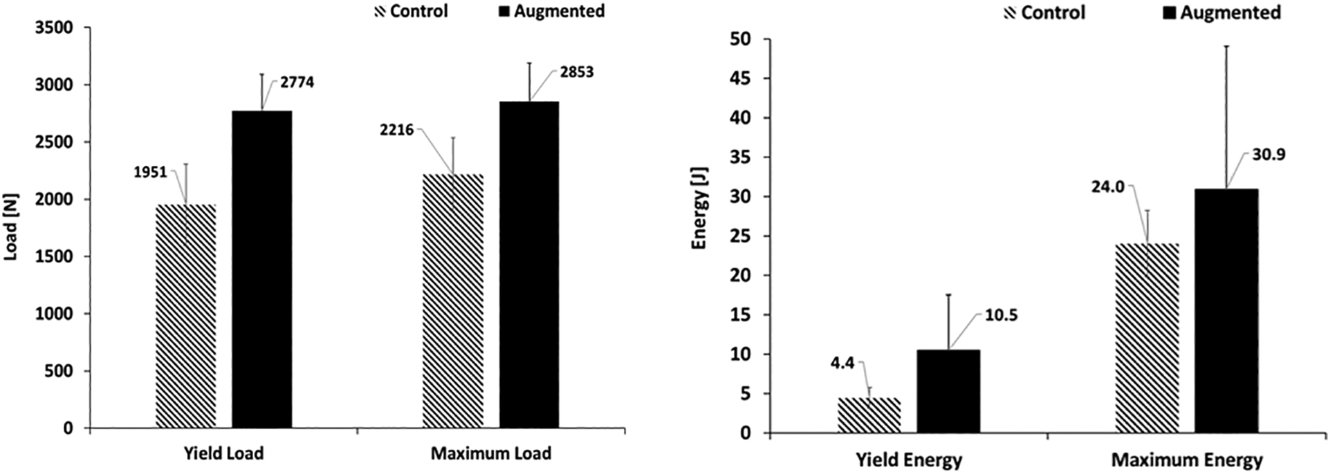
Effects of augmentation on yield and maximum load (left), yield and maximum energy (right) of the osteoporotic specimens measured in fracture tests. Error bars represent standard deviation.
Figure 7 –
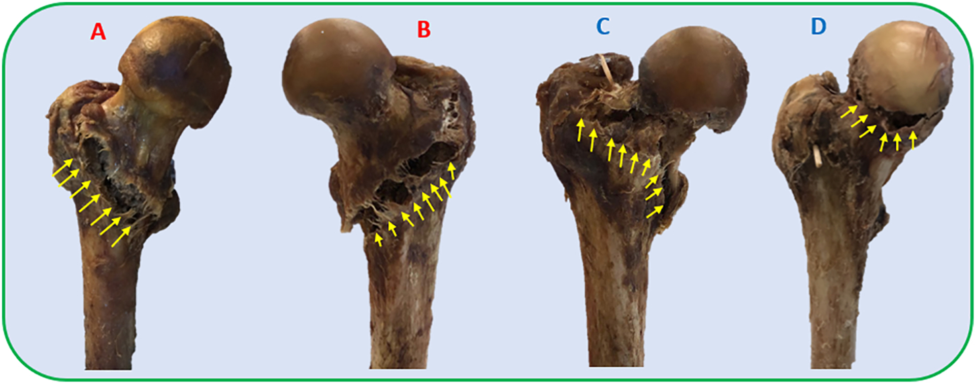
Patterns of fracture in side-way fall loading condition for A) Sample #1 from the control group, B) Sample #6 from the control group, C) Sample #6 of the augmented group; D) Sample #3 (osteopenic specimen). Note that the control samples experience an intertrochanteric fracture while the fracture pattern varies in the augmented group.
Femur specimens were registered to the segmented model of the bone with root mean squared errors of less than 1mm in all experiments. However, the error due to injector placement and pre-operative simulations yielded to an average distance error of 6.2 mm between the isosurface of planned and injected volume of PMMA.
Temperature recordings of the bone surface shows that the areas close to the greater trochanter will experience the highest temperature rise with an average peak temperature rise of 12.1 °C. The trochanteric crest and femoral neck experience a lower temperature rise with an average peak rise of 6.17 °C and 5.26 °C respectively. In all experiments, greater trochanter area of the bone experienced a temperature rise of over 8 °C for an average period of about 9.2 minutes. In four specimens, this area experienced a temperature rise of over 10 °C. Meanwhile, these critical exposures were only observed in one specimen for the trochanteric crest. Table 3 details the summary of the peak temperature rises and duration of the critical exposures for all specimens.
Table 3-.
Recorded temperature of the bone at the depth of 2mm from the surface at three anatomical regions. For the regions with potential risk of necrosis, exposure time of the temperature-rise was reported as well.
| Greater trochanter | Trochanteric crest | Neck | |||||||||
|---|---|---|---|---|---|---|---|---|---|---|---|
| # | PMMA Volume (ml) | Peak Temperature-rise (°C) | >8 °C [s] | >10 °C [s] | Peak Temperature-rise (°C) | >8 °C [s] | >10 °C [s] | Peak Temperature-rise (°C) | |||
| 1 | 7.1 | 10.65 | 354 | 155 | 7.20 | - | - | 7.96 | |||
| 2 | 10.5 | 13.89 | 528 | 410 | 7.42 | - | - | 7.69 | |||
| 3 | 9.4 | 9.31 | 227 | - | 3.23 | - | - | 2.83 | |||
| 4 | 8.3 | 12.28 | 771 | 465 | 2.68 | - | - | 2.68 | |||
| 5 | 9.1 | 8.91 | 333 | - | 12.30 | 772 | 524 | 6.12 | |||
| 6 | 10.3 | 17.77 | 1121 | 831 | 4.16 | - | - | 4.26 | |||
4. Discussion
In this in vitro study, we aimed to validate the fracture-related biomechanical outcomes of femoroplasty using a novel planning paradigm on human cadaveric femora with osteoporosis. The planning paradigm utilizes a gradient descent optimizer to determine a continuous pattern for PMMA injection. As expected, results demonstrated that osteoporotic specimens benefit greatly from injections that connect the supero-posterior aspect of the greater trochanter to the inferior aspect of femoral head. This distribution of bone cement is similar to the findings of other patient-specific plans (Basafa, 2015; Santana Artiles, 2017). The biomechanical effectiveness of injections is comparable to those of Basafa et al. (2015) where an average of 9.5 ml of cement increased the yield load by 33% and yield energy by 118%. The outcomes for these parameters have been increased by respectively 42% and 139% in the current study while the injection volume was reduced to 9.1 ml. Furthermore, the new plan did not require a second drill hole for any of the specimens. Although the investigation was beyond the scope of this study, it was determined that the osteopenic sample does not benefit from the augmentation. This femur fractured from the inferior part of the head which was different from the osteoporotic femora of both control and augmented groups (Fig. 7).
Previous studies have established that thermal necrosis may occur when tissue is exposed to temperatures higher than 60 °C. That is equivalent to the temperature rise of approximately 23 °C. Lower temperatures can still cause necrosis depending on the exposure time (Eriksson et al., 1983). Notably, temperatures of 45 °C (rise of ~8 °C) for over 600 s, 47 °C (rise of ~10 °C) for over 60 s, and 50 °C (rise of ~13 °C) for over 30 s leads to necrosis (Eriksson et al., 1983). Temperature recordings of bone surface in this study allowed for a quantitative assessment of this risk. Results presented in table 3 indicate that all the osteoporotic injection scenarios may risk thermal damage at the greater trochanter or trochanteric crest region of the bone. Future work will include the addition of a FE model that predicts the bone temperature (e.g., Farvardin et al., 2018) to the existing planning paradigm in order to remove the risk of thermal damage. In addition, integration of a cooling system with femoroplasty (e.g., Bakhtiarinejad et al., 2019) can extend the polymerization time of PMMA, thus reducing the risk of thermal necrosis due to the temperature rise. Approaches for the integration of a cooling system have been previously used for vertebroplasty (Chavali et al., 2003). It is important to note that our temperature rise estimation may be over-estimations since 1) initial tissue temperatures in all in vitro experiments of this study averaged ~21 °C, well below the normal body temperature (37 °C); and 2) lack of blood flow results in higher temperatures in cadaveric experiments. A more realistic evaluation of necrosis risk may be achieved through live tissue injections of PMMA.
The current study focused on PMMA based femoroplasty which is shown to be effective in several computational and experimental studies (e.g., Beckmann, 2011; Basafa, 2015; and Varga, 2017). However, a recent study showed that injections of biphasic calcium sulfate/hydroxyapatite (CaS/HA) in the proximal femur is also feasible and may lead to a reduction in fracture risk if cement is injected optimally (Kok et al., 2019). Such materials can eliminate the risk of thermal damage associated with the procedure. Additionally, the In-vitro study of Stroneck et al. proposed a triphasic calcium-based implant as an alternative approach material that is designed to replace the bone loss due to osteoporosis This material, however, is designed to be resorbed and replaced with host bone and may lose its mechanical properties over time. (Stroneck et al., 2019). Since the main candidates for femoroplasty are elderly with severe osteoporosis who have already fractured a hip, the remodeling of the bone is less significant than the biomechanical effectiveness of the augmentation-if the incidence of bone damage due to osteonecrosis can be controlled. Cooling strategies can be adopted to further reduce the already limited zone of thermal damage from PMMA, therefore, maintaining sufficient viable bone to allow for osteosynthesis and bone healing.
Among other limitations of this study is the accuracy of cement injection based on the plan. The average shape error between the injected and planned path of cementation remains relatively large in this study (6.2 mm average distance error). While the overall planning paradigm has been improved, intra-operative execution of the plan remains a challenge. Although specimens were injected with the same volume of cement as planned, the direction and location of cementation are different from the desired path, lowering the biomechanical benefits (e.g., increased bone strength). Since both bone and tool registrations have errors that average <1mm, it can be assumed that the error of the user drilling with provided visual feedback and injector placement are the major contributing factors for the injection accuracy. Therefore, the use of a robotic system for drilling and injection of bone cement may increase the accuracy of cementation, thus improving the overall reliability of the procedure by improving the biomechanical benefit and reducing the risk of cement leakage. The simplifying assumptions made in the SPH and errors in cement segmentation are other sources of error.
4. Conclusions
To summarize, this study shows that a planned injection of PMMA into the proximal femur can significantly improve its fracture-related biomechanical properties (yield load and yield energy) and can benefit the individuals at the highest risk. The new planning paradigm offers a more efficient injection strategy with the injection volume of 9.1 ml on average. Meanwhile, temperature recordings of bone surfaces suggest that the risk of thermal necrosis remains a concern with PMMA-based femoroplasty. This may require additional provisions (e.g., a cooling mechanism) to lower the curing temperature. Future work involves incorporating modes that predict bone temperatures and conducting surgical interventions that aim at lowering those temperatures during femoroplasty.
Highlights.
Osteoporotic hip augmentation improves the biomechanical properties.
Finite element analysis can predict the yield fracture load of the proximal femur.
Femoroplasty with Polymethylmethacrylate can cause thermal damage to the tissue.
Acknowledgments
We thank Dr. Stephen Belkoff and Mr. Demetries Boston of Johns Hopkins Bayview Medical Center for their help with providing the specimens and the DEXA. This work was supported by grants no. R21 AR063815 and R01 EB0223939 from National Institutes of Health. The funders had no role in the study design, data collection, analysis of the data, writing of the manuscript, or the decision to submit the manuscript for publication.
Footnotes
Publisher's Disclaimer: This is a PDF file of an unedited manuscript that has been accepted for publication. As a service to our customers we are providing this early version of the manuscript. The manuscript will undergo copyediting, typesetting, and review of the resulting proof before it is published in its final form. Please note that during the production process errors may be discovered which could affect the content, and all legal disclaimers that apply to the journal pertain.
Conflict of Interest Statement
None declared.
References
- Bakhtiarinejad M, Farvardin A, Chamani A and Armand M, 2019, November. A Conductive Cooling Scheme for Bone Augmentation of the Proximal Femur With PMMA: An Experimental and Finite Element Study. In ASME International Mechanical Engineering Congress and Exposition (Vol. 59407, p. V003T04A045). American Society of Mechanical Engineers. [Google Scholar]
- Basafa E Armiger RS Kutzer MD Belkoff SM Mears SC Armand M, 2013a. Patient-specific finite element modeling for femoral bone augmentation. Medical Engineering & Physics 35(6), 860–865. [DOI] [PMC free article] [PubMed] [Google Scholar]
- Basafa E Murphy RJ Kutzer MD Otake Y Armand M, 2013b. A Particle Model for Prediction of Cement Infiltration of Cancellous bone in Osteoporotic Bone Augmentation. PLoS One 8(6), e67958. [DOI] [PMC free article] [PubMed] [Google Scholar]
- Basafa E and Armand M, 2014. Subject-specific planning of femoroplasty: a combined evolutionary optimization and particle diffusion model approach. Journal of biomechanics, 47(10), pp.2237–2243. [DOI] [PMC free article] [PubMed] [Google Scholar]
- Basafa E, Murphy RJ, Otake Y, Kutzer MD, Belkoff SM, Mears SC and Armand M, 2015. Subject-specific planning of femoroplasty: an experimental verification study. Journal of biomechanics, 48(1), pp.59–64. [DOI] [PMC free article] [PubMed] [Google Scholar]
- Besl PJ and McKay ND, 1992, April. Method for registration of 3-D shapes. In Sensor fusion IV: control paradigms and data structures (Vol. 1611, pp. 586–606). International Society for Optics and Photonics. [Google Scholar]
- Beckmann J, Springorum R, Vettorazzi E, Bachmeier S, Lüring C, Tingart M, Püschel K, Stark O, Grifka J, Gehrke T and Amling M, 2011. Fracture prevention by femoroplasty—cement augmentation of the proximal femur. Journal of Orthopaedic Research, 29(11), pp.1753–1758. [DOI] [PubMed] [Google Scholar]
- Berry SD, Samelson EJ, Bordes M, Broe K and Kiel DP, 2009. Survival of aged nursing home residents with hip fracture. Journals of Gerontology Series A: Biomedical Sciences and Medical Sciences, 64(7), pp.771–777. [DOI] [PMC free article] [PubMed] [Google Scholar]
- Chavali R, Resijek R, Knight SK and Choi IS, 2003. Extending polymerization time of polymethylmethacrylate cement in percutaneous vertebroplasty with ice bath cooling. American journal of neuroradiology, 24(3), pp.545–546. [PMC free article] [PubMed] [Google Scholar]
- Eriksson AR and Albrektsson T, 1983. Temperature threshold levels for heat-induced bone tissue injury: a vital-microscopic study in the rabbit. Journal of prosthetic dentistry, 50(1), pp.101–107. [DOI] [PubMed] [Google Scholar]
- Farvardin A, Bakhtiarinejad M, Pozin M and Armand M, 2018, November. A Biomechanical and Thermal Analysis for Bone Augmentation of the Proximal Femur. In ASME 2018 International Mechanical Engineering Congress and Exposition (pp. V003T04A061–V003T04A061). American Society of Mechanical Engineers. [DOI] [PMC free article] [PubMed] [Google Scholar]
- Farvardin A, Basafa E, Bakhtiarinejad M and Armand M, 2019. Significance of preoperative planning for prophylactic augmentation of osteoporotic hip: A computational modeling study. Journal of biomechanics, 10.1016/j.jbiomech.2019.07.012 [DOI] [PMC free article] [PubMed] [Google Scholar]
- Fliri L, Sermon A, Wähnert D, Schmoelz W, Blauth M and Windolf M, 2013. Limited V-shaped cement augmentation of the proximal femur to prevent secondary hip fractures. Journal of biomaterials applications, 28(1), pp.136–143. [DOI] [PubMed] [Google Scholar]
- Gautier E, Ganz K, Krügel N, Gill T and Ganz R, 2000. Anatomy of the medial femoral circumflex artery and its surgical implications. The Journal of bone and joint surgery. British volume, 82(5), pp.679–683. [DOI] [PubMed] [Google Scholar]
- Karagas MR, Lu-Yao GL, Barrett JA, Beach ML and Baron JA, 1996. Heterogeneity of hip fracture: age, race, sex, and geographic patterns of femoral neck and trochanteric fractures among the US elderly. American journal of epidemiology, 143(7), pp.677–682. [DOI] [PubMed] [Google Scholar]
- Kok J, Širka A, Grassi L, Raina DB, Tarasevičius Š, Tägil M, Lidgren L and Isaksson H, 2019. Fracture strength of the proximal femur injected with a calcium sulfate/hydroxyapatite bone substitute. Clinical Biomechanics, 63, pp.172–178. [DOI] [PubMed] [Google Scholar]
- Kutzer MD, Basafa E, Otake Y and Armand M, 2011, January. An automatic injection device for precise cement delivery during osteoporotic bone augmentation. In ASME 2011 International Design Engineering Technical Conferences and Computers and Information in Engineering Conference (pp. 821–827). American Society of Mechanical Engineers. [Google Scholar]
- Melton LJ III and Cooper C, 2001. Magnitude and impact of osteoporosis and fractures. In osteoporosis (pp. 557–567). Academic Press. [Google Scholar]
- Melton LJ III, 2003. Adverse outcomes of osteoporotic fractures in the general population. Journal of Bone and Mineral Research, 18(6), pp.1139–1141. [DOI] [PubMed] [Google Scholar]
- Otake Y, Armand M, Sadowsky O, Armiger RS, Kutzer MD, Mears SC, Kazanzides P and Taylor RH, 2010, February. An image-guided femoroplasty system: development and initial cadaver studies. In Medical Imaging 2010: Visualization, Image-Guided Procedures, and Modeling (Vol. 7625, p. 76250P). International Society for Optics and Photonics. [Google Scholar]
- Santana Artiles ME and Venetsanos DT, 2017. A new evolutionary optimization method for osteoporotic bone augmentation. Computer methods in biomechanics and biomedical engineering, 20(7), pp.691–700 [DOI] [PubMed] [Google Scholar]
- Schneider EL and Guralnik JM, 1990. The aging of America: impact on health care costs. Jama, 263(17), pp.2335–2340. [PubMed] [Google Scholar]
- Schnell S, Friedman SM, Mendelson DA, Bingham KW and Kates SL, 2010. The 1-year mortality of patients treated in a hip fracture program for elders. Geriatric orthopaedic surgery & rehabilitation, 1(1), pp.6–14. [DOI] [PMC free article] [PubMed] [Google Scholar]
- Sevitt S and Thompson RG, 1965. The distribution and anastomoses of arteries supplying the head and neck of the femur. The Journal of bone and joint surgery. British volume, 47(3), pp.560–573. [PubMed] [Google Scholar]
- Stroncek JD, Shaul JL, Favell D, Hill RS, Huber BM, Howe JG and Bouxsein ML, 2019. In vitro injection of osteoporotic cadaveric femurs with a triphasic calcium‐based implant confers immediate biomechanical integrity. Journal of Orthopaedic Research®, 37(4), pp.908–915. [DOI] [PMC free article] [PubMed] [Google Scholar]
- Sutter EG, Mears SC and Belkoff SM, 2010. A biomechanical evaluation of femoroplasty under simulated fall conditions. Journal of orthopaedic trauma, 24(2), p.95. [DOI] [PMC free article] [PubMed] [Google Scholar]
- Varga P, Inzana JA, Schwiedrzik J, Zysset PK, Gueorguiev B, Blauth M and Windolf M, 2017. New approaches for cement-based prophylactic augmentation of the osteoporotic proximal femur provide enhanced reinforcement as predicted by non-linear finite element simulations. Clinical biomechanics, 44, pp.7–13. [DOI] [PubMed] [Google Scholar]


