

Abstract
Introduction. Prosthesis loosening is an alteration of the function and position of a total hip prosthesis with reference to the initial surgical moment. The main mechanism unanimously accepted for aseptic prosthetic losses at the level of the cup is represented by the biological mechanism. Material and Method. Experimental and virtual, interdisciplinary tools, techniques and methods were used to determine the behavior of the hip replacement prosthesis with the morcellated graft and the reconstruction net. Performing an orthopedic assembly with a morcellated bone graft and reconstruction net. An assembly was performed on a hip joint taken from an animal (cow). The biological material and the components of the prosthesis were prepared similarly to the revision prosthesis intervention. Experimental testing of orthopedic assembly with morcellated bone graft and reconstruction net. This assembly was tested on a universal machine to determine the maximum force at which it yields. This was 1790 Kgf, i.e. 17559 N. Virtual experimental testing of the hip joint with orthopedic revision assembly with a morcellated bone graft and reconstruction net for normal gait loading. The orthopedic assembly with the morcellated graft and the reconstruction net was reconstructed in the virtual environment. Normal load was used. Results maps were obtained. Conclusions. Analyzing the results from the two tests, experimental and virtual, and important conclusions were drawn regarding this orthopedic assembly.
Keywords: Lupus nephritis, autoantibody profile, renal biopsy
Introduction
Prosthesis loosening is an alteration of the function and position of a total hip prosthesis with reference to the initial operative moment. As synonyms there is also the notion of "loss" or "decimentation"-reserved for cemented cases [1,2,3].
In the natural evolution of an arthroplasty, loosening is a real phenomenon, which may appear sooner or later being influenced by a multitude of factors [4,5].
It has been observed that often the mechanisms intertwine, sometimes even potentiating by altering the bone-prosthesis/ bone-cement interface and less often, the cement-prosthesis interface [6,7,8,9].
The main unanimously accepted mechanism for aseptic prosthetic losses at the level of the cup is represented by the biological mechanism, more precisely “particle disease” or “wear” (metal-ceramic-polyethylene-acrylic cement), and in the case of the femoral component the prosthesis loss is strictly mechanical.
In this pathology, all these reactions are possible due to the rich cellularity of the periprosthetic pseudocapsule (monocytes, fibroblasts, macrophages) which, together with the vascular endothelial cells present in the periprosthetic fluid, causes the appearance of an aggressive osteolysis (Figure 1).
Figure 1.

Intraoperative appearance with false membranes and periprosthetic corrosion areas
In the osteolysed space appears an interposition tissue with a low vascularity, rich in fibroblasts and with an acidic pH.
This pH in turn negatively influences osteocytes.
Activation of macrophages causes the release of proinflammatory cytokines that alter the function and phenotype of bone cells, in the sense that they activate osteoclasts by inhibiting osteoblasts.
The causes of bone deficiency can be primary intervention, implant migration and osteolysis determined by particle disease.
Assessment of bone defects is done by anteroposterior pelvic X-ray (AP) and profile or more useful Orthogonal X-ray, plus postoperative control radiographs [10].
Bone graft can be:
- autograft is limited in quantity, but has the best integration capacity;
- allograft-fragmented (bone fragments 0.5-1cm) or structural is indispensable in all bone defects.
The restoration of the local anatomy being a major objective in the acetabular revision [11,12].
The morcellated graft proved to have a predictable integration.
Numerous studies show very good results (cup migration <5mm at 7 years, full integration according to CONN criteria and CT examination) in the case of the impacted bone graft.
It is mandatory to prepare the receiving bed and a dense layer of at least 5mm thick.
The most common source is fresh-frozen allograft from the femoral head, 1/3 distal femur or 1/3 proximal tibia [13,14,15,16].
Material and Method
Specific tools for orthopedic surgery were used to obtain orthopedic fixtures.
Some of them are shown in Figure 2 and are used for milling the acetabular cavity and adapting to the components of the prosthesis, but also for cutting and removal.
Figure 2.

Tools used to adapt the bone component to prosthetic elements
Materials used to obtain the prosthetic assembly, such as orthopedic cement and surgical gloves, were also used, as shown in Figure 3.
Figure 3.

Additional materials used to obtain orthopedic fixtures
The universal test machine with hydraulic drive EDZ 20 of maximum load 20tf (200 kN) was used to perform the experimental tests.
The tension/compression request is made between the fixed crossbar, whose position can be adjusted and the upper crossbar of the movable frame driven by a hydraulic motor that allows it to make a movement in the vertical direction.
The intensity of the load force is indicated (throughout the test) on the graduated panel of the control block [17,18,19].
For the analysis of the images obtained after the rupture of the tested orthopedic systems, a digital stereo microscope of the INSIZE ISM-PM200SB type was used, having the following technical characteristics:
- magnification power 10x ... 200x.
- powered via USB port to notebook.
- the software can measure distances, angles, areas.
- consists of the actual lens, stand and microvisa for adjusting the FOCUS [17,18,19].
For the reconstruction of bone tissues obtained by tomography, the Geomagic program was used, which is mainly used in reverse engineering, which allows the editing or modification of "point clouds" obtained by three-dimensional scanning or computed tomography [17,18,19].
InVesalius is free medical software used to generate virtual reconstructions of structures in the human body.
Based on two-dimensional images, obtained using computed tomography or magnetic resonance equipment, the software generates virtual three-dimensional models corresponding to the anatomical parts of the human body.
After building three-dimensional DICOM images, the software allows the generation of STL (stereolithography) files. These files can be used for rapid prototyping [17,18,19].
SolidWorks is a computer aided design (CAD) and computer aided engineering (CAE) program that runs primarily on Microsoft Windows, being a good virtual solids modeler, using a parametric approach based on different features [17,18,19].
Ansys Workbench is a finite element analysis software that allows the study of the behaviors of different mechanical or biomechanical systems and that can highlight through result maps the displacements, strains and stress that appear in orthopedic assemblies that are based on revision prostheses [17,18,19].
Five coxofemoral joint assemblies of bovine origin were processed. Initially, they were skeletalized by the soft tissues and, later, specific acetabular bone defects were reproduced, in correlation with the Paporsky classification.
These were selected from a group of nine hip joints so that they were similar in shape and size.
This study was approved and assumed by the Ethics Commission of the University of Medicine and Pharmacy of Craiova.
Results
To obtain this assembly, a morcellated bone graft was created as shown in Figure 4 using a hip joint taken from the animal (cow).
Figure 4.

Obtaining the morcellated bone graft
The areas to be removed were marked on the bone taken from the animal to simulate bone loss, as shown in Figure 5.
Figure 5.

Marking areas to be removed
These marked areas were removed using specific instrumentation and the positioning of the polyethylene cup was tested (Figure 6).
Figure 6.

Remove marked areas and position the cup
The morcellated bone graft was placed in the acetabular cavity and adjusted in the areas with bone loss using the specific instrumentation (Figure 7).
Figure 7.

Location of the morcellated bone graft
Next, the reconstruction net was prepared, cut and adjusted to the required dimensions so as to completely cover the morcellated bone graft, as shown in Figure 8.
Figure 8.

Preparation of the reconstruction net
Next, the reconstruction net was fixed using orthopedic screws and the positioning of the polyethylene cup was checked, as shown in Figure 9.
Figure 9.

Fixing the reconstruction net with screws
Finally, the acetabular cavity was covered with orthopedic cement and the assembly was obtained with a morcellated bone graft and reconstruction net, as shown in Figure 10.
Figure 10.

Final assembly with morcellated bone graft and reconstruction net
The orthopedic assembly with morcellated bone graft and reconstruction net was placed in the fixing device.
The prosthesis stem was also attached to the upper device of the fastening system so that the action of the force was vertical.
Figure 11 shows the assembly with morcellated bone graft and reconstruction net on the EDZ 20 test machine.
Figure 11.

Assembly with a morcellated bone graft attached to the EDZ 20 test machine
The force was gradually amplified until the orthopedic assembly with a morcellated bone graft and reconstruction yielded mechanically.
The value of 1790 Kgf, ie 17559 N, was read on the panel of the universal EDZ 20 machine.
After the assembly failed, it was studied and analyzed with the INSIZE ISM-PM200SB digital stereomicroscope, a series of images being presented in Figure 12.
Figure 12.

Images and measurements made with the stereomicroscope
The hip joint model with orthopedic revision assembly with morcellated bone graft and reconstruction mesh was first modeled in SolidWorks starting from tomographic images and adapted with the Geomagic program, then loaded in Ansys Workbench, and the interface of this program is presented in Figure 13.
Figure 13.

Ansys Workbench program interface after loading the analyzed model
First of all, the structure of finite elements was performed and 343182 elements with a maximum size of 2mm and a tetrahedral shape were obtained.
Figure 14 shows the finite element structure of the analyzed system.
Figure 14.

The finite element structure of the analyzed system
In order to perform a Static Structural analysis, it was considered that the system has fixation surfaces in the condylar area of the femoral bones, and it was considered a variation of the force between 800 and 2300 N during a second and positioning on the sacrum.
The Ansys program has a module that stores the materials used, but also their characteristics, called Engineering Data.
It was considered that the morcellated graft is already osseointegrated and can be considered similar to the trabecular bone.
In this Engineering Data module, the materials that make up the analyzed orthopedic system were defined and activated.
After running the application, result maps were obtained. Figure 15 shows the travel map of the analyzed system.
Figure 15.

The displacement map
Figure 16 shows the strain map.
Figure 16.

The strain map
Figure 17 shows stress maps.
Figure 17.
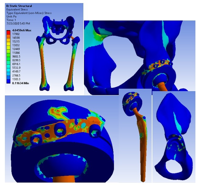
Stress maps
Discussion
There are several ways of bone reconstruction that can be used in the revision of the acetabular cup, all with the ultimate goal of restoring the initial anatomy as much as possible.
The use of the grafted graft form ensures its complete integration with the restoration of the bone walls.
The role of the reconstruction net is to improve the primary stability of the assembly, which as shown in the study, is similar to other ways of reconstruction [17,18,19].
Subsequently, the integration of the graft ensures the restoration of local bone capital.
This is the key element necessary for the long-term stability of the acetabular cup, thus being able to discuss a biological bone reconstruction.
In addition, this type of reconstruction facilitates possible surgeries, as it restores bone capital [9].
The demands to which this type of assembly was subjected, obtained from the reconstruction with the morcellated bone graft and the reconstruction mesh are similar to some current daily activities.
The assembly with morcellated graft and reconstruction net yielded to the force of 1790 Kgf, ie 17560 N, values very close to the maximum value of the force determined for other similar orthopedic assemblies [10,14].
Analyzing the more stressed areas and surfaces from four other overhaul fixtures, the maximum stresses are found on the prosthesis elements, and the bone components that are in contact with them are less stressed [7,17,18,19].
The assembly proved its effectiveness, proving a good primary stability, and with the integration of the graft, the bone capital is restored, ensuring a stability similar to human bone tissue [8].
Conclusions
The following general conclusions were also highlighted:
- using CAD and FEM methods, very complicated biological systems can be modeled and simulated;
- the virtual models studied in this paper have been experimentally certified;
- finite element analysis methods, coupled with virtual reconstruction of CT or MRI images and reverse engineering methods, pave the way for the innovation of customized orthopedic systems for each patient.
These conclusions were validated both by experimental testing and by finite element analysis, using the load specific to normal human gait.
Conflict of interests
None to declare.
References
- 1.Ionescu M, Baciu CL, Buzescu G. Postero-external access path on the hip (in Romanian) Chirurgia (Bucharest) 1962;11(1):131–137. [Google Scholar]
- 2.Weber ER, Daube JR, Coventry MB. Periphereal neuropathy associated with total hip arthroplasty. J B Jt Surg. 1976;58(1):66–73. [PubMed] [Google Scholar]
- 3.Witvoet J. Ortopedie. 1. Vol. 4. Paris, 44667: Techniques; 1990. Technique de pose d’une prothese totale de hanche a cotyle vise. Encyl. Med. Chir; pp. 1–14. [Google Scholar]
- 4.Wootson ST. 1. Vol. 1. New York, USA: Lippincott-Raven; 1998. Blood conservation (Perioperative Considerations) in The Adult Hip. (Callaghan J.J., Rosenberg G.A., Rubash E.H.) pp. 625–632. [Google Scholar]
- 5.Zaharia C. In: Elements of locomotor system pathology (in Romanian. Zaharia C, editor. Bucharest: Padeica; 1994. Hip arthroplasty; pp. 303–310. [Google Scholar]
- 6.Harris WH, Sledge CB. Medical progress: Total hip and total knee replacement. N Engl J Med. 1990;323(2):725–731. doi: 10.1056/NEJM199009133231106. [DOI] [PubMed] [Google Scholar]
- 7.Ahmed AM, Raab A, Miller JE. Metal/cement interface strength in cemented stem fixation. J Orthop Res. 1984;2(1):105–118. doi: 10.1002/jor.1100020201. [DOI] [PubMed] [Google Scholar]
- 8.Mulroy WF, Harris WH. Revision total hip arthroplasty with use of so-called second-generation cementing techniques for aseptic loosening of the femoral component. A fifteen-year-average follow-up study. J Bone Joint Surg Am. 1996;78(1):325–330. doi: 10.2106/00004623-199603000-00002. [DOI] [PubMed] [Google Scholar]
- 9.Harris WH, Schiller AL, Scholler JM, Freiberg RA, Scott R. Extensive localizated bone resorbtion in the femur following total hip replacement. J B Jt Surg AM. 1976;58(1):612–618. [PubMed] [Google Scholar]
- 10.Hann CD, Yang IH, Kang ES, Kim J, Kim NH. A comparative experimental study of bone in growth and ossteointegration in hidroxyapatite-coated vs. porous-coated implant [abstract] British J B Jt Surg. 1996;78(1) [supplement):184–186. [Google Scholar]
- 11.Goldstein SA. The mechanical properties of trabecular bone: dependence on anatomic location and function. J Biomech. 1987;20(2):1055–1061. doi: 10.1016/0021-9290(87)90023-6. [DOI] [PubMed] [Google Scholar]
- 12.Engh CA, Massin P, Suthers KE. Roentgenographic assessment of the biologic fixation of porous-surfaced femoral components. Clin Orthop Relat Res. 1990;257(4):107–128. [PubMed] [Google Scholar]
- 13.Dawson J, Fitzpatrick R, Carr A, Murray D. Questionnaire on the perceptions of patients about total hip replacement. J Bone Joint Surg [Br] 1996;78(1):185–90. [PubMed] [Google Scholar]
- 14.Dawson J, Fitzpatrick R, Murray D, Carr A. Comparison of measures to assess outcomes in total hip replacement surgery. Qual Health Care. 1996;5(2):81–88. doi: 10.1136/qshc.5.2.81. [DOI] [PMC free article] [PubMed] [Google Scholar]
- 15.Dawson J, Fitzpatrick R, Murray D, Carr A. The problem of ‘noise’ in monitoring patient-based outcomes: generic, disease specific and site-specific instruments for total hip replacement. J Health Serv Res Policy. 1996;1(1):224–231. doi: 10.1177/135581969600100408. [DOI] [PubMed] [Google Scholar]
- 16.McMurray R, Heaton J, Sloper P, Nettleton S. Measurement of patient perceptions of pain and disability in relation to total hip replacement: the place of the Oxford hip score in mixed methods. Qual Health Care. 1999;8(2):228–233. doi: 10.1136/qshc.8.4.228. [DOI] [PMC free article] [PubMed] [Google Scholar]
- 17.Popa DL, Duţă A, Tutunea D, Gherghina G, Buciu G, Calin DC. Virtual Methods Applied to Human Bones and Joints Re-Construction Used for Orthopedic Systems. Applied Mechanics and Materials. 2016;822(1):160–165. [Google Scholar]
- 18.Calin D, Tarniţă D, Popa D, Calafeteanu D, Tarnita DN. Virtual Model and Simulation of the Normal and Affected Human Hip Joint. Applied Mechanics and Materials. 2016;823(1):167–172. [Google Scholar]
- 19.Calin D, Tarniţă D, Popa D, Rosca A, Tarnita DN. The 3D Virtual Model of a Classical Hip Joint Prosthesis. Applied Mechanics and Materials. 2016;823(1):161–166. [Google Scholar]