

Abstract

Visible-light absorption is a critical factor for photocatalyst activity and absorption of electromagnetic (EM) interference application. The band gap of Fe2O3 is 2 eV, which can be increased by doping with a high-band-gap material such as carbon from activated carbon (AC) with a band gap of 4.5 eV for increased visible-light absorption. The porosity decreases from 88 to 81.6%, and the band gap increases from 2.14 to 2.64 eV by increasing the AC from 10 to 25%, respectively. The photocatalytic activity takes 120 min to produce a harmless product for 10–20% AC, but 25% AC shows 89.5% degradation in only 90 min and the potential to attenuate the EM wave up to 99% due to the RL being below −20 dB. The second- and third-cycle degradation achieved by the composite Fe2O3–AC having 25% AC is 88.2 and 86.5% in 90 min, respectively. The pore of the surface state of AC contains a trapped charge, and interaction occurs between the charge (electron/hole) and O2 or H2O to produce OH and superoxide (O2–) radicals. These radicals move inside the molecule of the pollutant (methylene blue (MB)) to break up the bond, with the final products being H2O and CO2. The X-ray photoelectron (XPS) spectra show that oxygen plays a key role in the interatomic bonding with Fe, C, and MB atoms. The best absorption of EM interference is −21.43 dB, with degradation reaching 89.51% in only 90 min for 25% AC due to its higher band gap and anisotropy constant. Fe2O3–carbon is a multifunctional material for the green environment because of its electromagnetic interference absorption and photodegradation of wastewater.
1. Introduction
The lifestyle of humans in the modern and digital era has increased the demand for textile and electronic products, leading to the development of new industries for supporting the demand.1−4 The textile industry has been contributing to environmental pollution due to the increasing use of toxic chemicals in the processing stage,5−9 which is of concern, especially the wastewater treatment before disposal.10 About 40% of the dyes used globally contain organic synthetic bound chlorine, which affects the environment by reducing oxygen concentration and preventing light at the water surface, consequently damaging the aquatic ecosystem.11,12 This in turn cause diseases in humans, who are exposed to the organic synthetic bound chlorine through the water and contaminated food. The chlorine’s effects can vary from cough and chest pain to water retention in the lungs,13,14 and irritation in the skin,15 eyes,16 and the respiratory system.17−19 The increasing demand for electronic devices has consequently increased their production, which has directly led to increase in electromagnetic interference (EMI) waves.20−26 EMI has been identified as a new type of pollution that interferes with electronic communications devices and causes threats to human health.20−24,27−29 Humans can absorb the pollution and radiation from the electromagnetic (EM) waves; therefore, scientists globally are looking for a way to efficiently shield and absorb these EM waves. There are two main problems with increase in the population globally, which have side effects on human health, they are the availability of clean water and energy. Therefore, innovations with regard to manufacturing efficient energy, water, and chemicals by using multifunctional materials for wastewater treatment and absorption of EM waves are crucial. This innovation can support sustainable development goals (SDGs): point 6 and point 7.3
The innovations in multifunctional materials have led to photodegradation of wastewater and EM wave absorption by tuning the electronic (band gap), magnetic, and optical properties to increase the absorption from UV light to visible light.20−26,30−32 A semiconductor material has unique properties that make it easy to tune these properties, so it is suitable for electromagnetic wave absorption and photocatalyst applications.33−36 Among the semiconductor materials, one of the binary semiconductors is Fe2O3, with a band gap of about 2 eV, natural abundance, electrochemical stability, and low toxicity.37,38 The limitations of this material are its poor electrical conductivity and optical properties for absorbing the solar spectrum only for wavelengths >600 nm. By doping with high-band-gap materials, the optical absorption is enhanced in the visible regions.39 Activated carbon (AC) increases the band gaps of CuO23 and Fe3O420 for absorbing EM wave interference.21,24,40 AC is used to tune the structural, magnetic, and optical properties of the semiconductor by doping it with various materials22,25,26,41 depending on the application.23,42−46 In our previous study, we successfully used Co/Fe2O3–AC for EM absorbers,47 but the physical phenomena between Fe2O3 and AC are still not fully understood. Several questions exist regarding the relations between the optical, magnetic, electronic, and structural properties that support the applications of multifunctional materials. What relation between these properties supports the capability of Fe2O3–AC in absorption of EM and photodegradation of wastewater? What is the effect of carbon on the performance of Fe2O3–AC in multifunctional purposes? The following approach (explained in the Materials and Experiment section) addresses these questions regarding the Fe2O3–AC materials.
In this study, the optical band gap of Fe2O3 is increased by doping with the carbon from AC for enhancing visible-light absorption in the photodegradation activity and absorption of EM waves. The relations between the structural, electronic, magnetic, and optical properties in supporting the multifunctional applications of the semiconductor Fe2O3–carbon are analyzed and discussed. Various amounts of carbon affect differently the structural and chemical bonding properties of Fe2O3,26,48−51 which were identified using X-ray diffraction (XRD), Fourier transform infrared (FTIR) spectroscopy, and X-ray photoelectron spectroscopy (XPS). The optical properties (refractive index (n and k)) and dielectric function (ε) of the semiconductor Fe2O3–carbon were determined from the quantitative analysis of the FTIR spectra using Kramers–Kronig (KK) relation. This method was successfully applied for the following materials: the composite cement/BaSO4/Fe3O4,52 composite geopolymer fly ash–metal,53 Co/Fe2O3–AC,47 nanoparticle Zn(OH)2,54 composite Fe/CNs/PVA,55 bioplastics (SPF/starch/chitosan/polypropylene),56 and composite nanocrystalline carbon–lignin/zinc oxide.57 The magnetic properties are measured using a vibrating sample magnetometer (VSM) for various amount of carbon in Fe2O3. X-ray photoelectron spectroscopy (XPS) was used for identifying the interactions and bonding states at the interatomic level. Reflection electron energy loss spectroscopy (REELS) was used for determining the optical band gap.20,25,26,39,41,49−51,58 The EM wave absorption performance was analyzed using the vector network analysis (VNA) in the frequency range from 2.5 to 8 GHz. For photocatalytic performance, the UV–vis spectra were recorded every 30 min using the irradiation from a halogen lamp with methylene blue as a model of wastewater.
The proposed processes for increasing the efficiency of the composite materials in this study are the following:
-
1.
To enhance visible-light absorption, the band gap is increased by increasing the amount of AC determined from the low-loss energy region of the REELS spectra (the basic idea can clearly be seen in Figure 1).
-
2.
The stable bonding is due to AC’s hexagonal structure, which quickly spreads and converts the EM to thermal energy when entering the composite (the basic idea can clearly be seen in Figure 1).
-
3.
Recombination between the charges (electrons and holes) is reduced during the photodegradation process in the magnetic pore (of AC) by trapping the charge and generating the oxidants hydroxyl radical (OH) and superoxide anion radical (O2–). This process, via photoelectrochemical decomposition of H2O and O2, consequently increases the photodegradation performance in the visible-light region (the basic idea can clearly be seen in Figure 2).
Figure 1.

Illustration of the mechanism for enhancing visible-light absorption by varying the amount of activated carbon (AC). When the EM wave enters the material, the interaction occurs with the atoms, and the energy spreading into the small waves produces vibration of the atoms and the lattice structure, and some of the energy is converted to thermal energy.
Figure 2.

Proposed photodegradation process. The photon energy absorbed by the electron in the valence band moves to the conduction band; the remaining hole, which goes to the surface of the material, is captured by the magnetic pore for generating OH and the superoxide anion radical (O2–) via photoelectrochemical decomposition of the H2O and O2 molecules for breaking the chemical structure of the pollutant, finally giving a harmless product.
2. Results and Discussion
Figure 3 shows the XRD full spectrum (a), the enlarged diffraction peaks (104) and (110) (b), and the FTIR spectra (c) for Fe2O3–carbon. The intensity of the diffraction peak for the composite Fe2O3–carbon shows that the Fe2O3 diffraction peak is dominant as expected, due to the composite’s high concentration. For further analysis, the Scherrer and size strain plot (SSP) methods were used in the XRD pattern to determine AC’s effect on the structural properties of the composites. The FTIR pattern shows the dominant peaks at a low wavenumber, usually for the vibration mode of metals.20 From 400 to 550 cm–1 is the vibration between Fe2O3 and other O or C atoms. The peaks arise from C bonding with −CH, −OH, and =C, and the O–H vibration mode from another small transmittance. The FTIR pattern is used to further determine the optical properties and dielectric function of the composite semiconductor Fe2O3–carbon for the strong peaks at the wavenumbers (ω) from 400 to 550 cm–1.59 For these purposes, Kramers–Kronig (KK) relation is used in the quantitative analysis of the FTIR pattern.
Figure 3.

(a) X-ray diffraction (XRD) full spectrum, (b) enlarged diffraction peaks (104) and (110), and (c) Fourier transform infrared (FTIR) spectra for the composite Fe2O3–carbon as a function of the amount of carbon. We have included ICDS 98-008-8414 for comparison.
The XRD diffraction pattern was used to determine the physical quantity, the full width at half-maximum (βhkl), the wavelength source of the radiation (λ), which in this study was 1.54056 Å for Cu Kα, and the angle (θ) of the diffraction peaks. βhkl was determined from the instrumental broadening (βinstrumental) by using Gaussian correction compared with the data for the standard crystalline Si.30,32,60−63 The relation between βhkl, βinstrumental, and βmeasures is represented by30
| 1 |
βhkl was used as an input parameter to determine the crystallite size using the Scherrer equation as follows
| 2 |
The dislocation density calculated from the crystallite size D is presented in Table 1, and is related to the defects in Fe2O3–carbon crystal structure, lattice parameter, volume crystal, porosity, and bond length.
| 3 |
| 4 |
| 5 |
where V is the volume, u is an internal parameter, and L is the bond length. The porosity is >80% for all composites, indicating the potential for absorbing the electromagnetic waves.23
Table 1. Quantitative Analysis of the XRD Spectra for Determining the Crystallite Size, Lattice Parameter, and Porosity of the Composite Semiconductor Fe2O3–Carbon.
| lattice
parameter (Å) |
||||||||
|---|---|---|---|---|---|---|---|---|
| sample ID | D (nm) | a | c | volume (VCal) | ratio (c/a) | dislocation density (1/D2) (nm–2) | porosity (%) | bond length (Å) |
| Fe2O3 | 15.33 | 5.02 | 13.71 | 299.4 | 2.73 | 0.0043 | 89.87 | 4.04 |
| 10% AC | 11.06 | 5.00 | 13.63 | 295.1 | 2.73 | 0.0082 | 88.02 | 4.02 |
| 15% AC | 14.01 | 5.04 | 13.70 | 301.4 | 2.72 | 0.0051 | 85.46 | 4.04 |
| 20% AC | 12.29 | 5.00 | 13.64 | 295.5 | 2.73 | 0.0066 | 82.72 | 4.02 |
| 25% AC | 15.76 | 4.97 | 13.58 | 290.5 | 2.73 | 0.0040 | 81.63 | 4.00 |
Figure 3b shows that the peaks were shifted to a higher 2θ; the porosity decrease is attributed to the carbon content increase in the composite, which may be due to the oxygen content decrease and the C atoms replacing some of the O atom positions in bonding with Fe. Therefore, the solid solution composite probably formed CxFeO1–x. The porosity linearly affects the surface area, which affects the properties of the material. This implies that the amount of C in the composite semiconductor Fe2O3–carbon and the formation of vacancies in the solid solution are increasing. The oxygen might decrease more probably around the Fe atoms rather than the C atoms. This is due to the differences in valence electrons between the C and Fe atoms. The oxygen decrease due to the bonds among them causes weak asymmetry of the local bond. The local bonding between a C atom and another C atom is dominantly covalent and metallic, and has an ionic character in a few clusters of crystal structures.64 For 15% AC, the shift to the lower 2θ, probably due to the crystal structure’s local strain and bond asymmetry from the C atoms, was not in the stable position in the lattice structure.20,24,30
The C atoms neighboring the Fe atoms would experience weak covalent bonds compared with the neighboring O atoms. This result implies that C bonding with O atoms plays an essential role in determining the lattice parameters. In particular, the carbon content significantly affects the lattice parameter.20−22,30,32,58
The microstrain (ε) contributes to the broadening βstrain = 4ε tan θ66−68 and the full width at half-maximum (β) as follows
| 6 |
where D is the crystallite size (nm), ε is the microstrain, β is the full width at half-maximum, and k is 0.94.
The models for the quantitative analysis of the XRD pattern for determining the structural properties are used at a high diffraction angle for high-accuracy results, and the size strain plot (SSP) method is applied at a low diffraction angle for better accuracy.61,65,68 The SSP model is described in detail as30,32,63,65,69,70
| 7 |
where d is the spacing between the atoms (Å) and ε is the microstrain. The contribution of the isotropic lattice is determined from the Gaussian functions and D is determined from the Lorentz functions. Figure 3a shows the Scherrer method and Figure 3b shows the SSP plot for the Fe2O3/AC composite; the corresponding structural properties are shown in Table 2. Figure 4 shows clearly the difference between the Scherrer and SSP methods; all data (indicated by the dotted lines) in the SSP plot shown close to the solid line indicate the high accuracy of the calculation methods.
Table 2. Quantitative Analysis of the XRD Spectra by Applying Scherrer and Size Strain Plot (SSP) Methods for Determining the Structural Properties of the Composite Semiconductor Fe2O3–Carbon.
| Scherrer method | SSP |
||||
|---|---|---|---|---|---|
| sample ID | D (nm) | D (nm) | E (10–3) | σ (Mpa) | u (Kj m–3) |
| Fe2O3 | 15.33 | 31.51 | 0.17 | 38.25 | 3.18 |
| 10% AC | 11.06 | 25.02 | 0.11 | 24.89 | 1.40 |
| 15% AC | 14.01 | 27.01 | 0.30 | 66.47 | 10.13 |
| 20% AC | 12.29 | 23.99 | 0.29 | 63.09 | 9.30 |
| 25% AC | 15.76 | 25.27 | 0.47 | 99.76 | 23.69 |
Figure 4.

(a) Scherrer and (b) size strain plot (SSP) methods for the analysis of the XRD spectra in Figure 3a. Optical properties: (c) refractive index (n) and extinction coefficient (k), and (d) the real (ε1) and imaginary parts (ε2) of the dielectric function from quantitative analysis of the FTIR spectra in Figure 3c.
The D average and ε determined from the Scherrer and SSP methods are shown in Table 2. Figure 4a,b, and Table 2 show that the D from the Scherrer method is smaller than that from the SSP method due to the effect of ε and the distance between the atoms included in the SSP method.30,32,63
The FTIR spectra were used for determining the refractive index (n), extinction coefficient (k), and dielectric function based on the following equations. First, the pattern was converted from transmittance T(ω) to reflectance R(ω)71−82
| 8 |
| 9 |
The reflectance pattern R(ω) is the input spectra used for determining n(ω) and k(ω) as follows73,74
| 10 |
| 11 |
where the phase change φ(ω) is the reflection of the photon after traveling inside the sample
| 12 |
The φ(ω) is made more simple for computation by applying the KK relation73,75
| 13 |
where j is the series of the wavenumber; if j is an odd number, then the i values are 2, 4, 6, 8, ..., j – 1, j + 1 and if the wavenumber j is even, the i values are 1, 3, 5, 7, ..., j – 1, j + 1, ...; Δω = ωi+1 – ωi. The n(ω) and k(ω) values from the analysis of FTIR spectra are shown in Figure 4c. The lower intersection wavelength point between n(ω) and k(ω) is the transverse optical (TO) mode and the higher one is the longitudinal optical (LO) phonon vibration mode, as clearly shown in Figure 4c.
The dielectric functions for the real part ε1(ω) and imaginary part ε2(ω) were determined as follows
| 14 |
| 15 |
Figure 4d shows the dielectric function in the form of real (ε1(ω)) and imaginary parts (ε2(ω)). At the surface layer, the breaking of the interatomic bonding happens, and the new structure formed is indicated by the dielectric function peaks in the range from 430 to 450 cm–1.76 Δ(LO-TO) is the distance between two optical phonon modes, which decreases on increasing the concentration of carbon in the composites as presented in Table 3, probably due to the nonuniformity of the lattice in the composite semiconductor Fe2O3–carbon, and consequently the less stable structure.77,78
Table 3. Band Gap Derived from the REELS Spectra in Figure 5aa.
| sample | band gap (eV) | To (cm–1) | Lo (cm–1) | Δ(Lo-To) (cm–1) | ε1 (cm–1) | kr | R2 |
|---|---|---|---|---|---|---|---|
| Fe2O3 | 2.00 | 446.42 | 491.09 | 44.67 | 432.85 | 0.020 | 0.998 |
| 10% AC | 2.14 | 444.49 | 491.94 | 47.45 | 431.04 | 0.023 | 0.992 |
| 15% AC | 2.30 | 449.30 | 491.52 | 42.22 | 436.80 | 0.022 | 0.955 |
| 20% AC | 2.50 | 448.34 | 490.26 | 41.92 | 434.65 | 0.027 | 0.977 |
| 25% AC | 2.64 | 448.64 | 490.68 | 42.04 | 435.08 | 0.030 | 0.987 |
Transverse optical phonon (To) and longitudinal optical phonon (Lo), and the real (ε1) and imaginary parts (ε2) of the dielectric function from the quantitative analysis of the FT-IR spectra in Figure 3c. The rate constant (kr) and correlation coefficient values (R2) for Fe2O3 and the composite semiconductor Fe2O3–carbon for 10, 15, 20, and 25% AC from the degradation analysis in Figure 6c,d.
The details of determining the band gap from the low-loss region of the REELS spectra have been reported in some previous studies.20,25,26,39,49,50,79,80Figure 5a shows the band gap of Fe2O3–carbon determined from the low-loss region’s REELS spectra. The corresponding values of these band gaps are shown in Table 3. The band gap increases from 2.0 eV for Fe2O3 to 2.64 for 25% AC due to the amount of AC, as the more vital interaction between the C 1s from AC with the Fe 3d and O 2p from Fe2O3 makes the top of the valence bands become thin.48 The bottom of the conduction bands is also changed after the introduction of AC into the composite Fe2O3–carbon. The mixing of the C 1s states at the valence band edge decreases the valence bandwidth; the increase of the band gap increases the amount of AC probably due to the formation of C1–x(Fe2O3)x. These results increase the photon excitation energy, which contributes to the generation of electrons and holes, consequently increasing the absorption and degradation ability.81 The generated electrons and holes move to the surface of the semiconductor Fe2O3 and jump to the pore as a charge trap for decreasing the recombination.82
Figure 5.

(a) Band gap determined from the low energy loss region of the reflection electron energy loss spectroscopy (REELS) spectra at primary energy Eo = 1500 eV. (b) Magnetic properties determined by VSM, and (c) reflection loss properties of Fe2O3–carbon for various amounts of carbon (10%, 15%, 20%, and 25% AC).
Figure 5b shows the magnetic properties measured at room temperature using a vibrating sample magnetometer with applied field −10 kOe < H < 10 kOe. From the hysteresis loops, the coercivity (Hc), saturated magnetization (Ms), and remanent magnetization (Mr) were analyzed and used to determine the remanent ratio (R) and isotropic constant (K1); the corresponding results are shown in Table 4. The composite Fe2O3–carbon in this study shows a multidomain soft ferrimagnetic nature due to the high coercivity (Hc) ranging from 1323.75 Oe for 10% AC decrease to 444.40 Oe for 25% AC, and a low saturation magnetization (Ms) ranging from 0.390 emu/g for 10% AC increase to 0.524 emu/g for 25% AC. The short-range exchange interaction leads to a more substantial magnetic ordering of all spins from the AC, resulting in increase in the Ms.83
Table 4. Magnetic Properties and Reflection Loss Properties Determined from Figure 5b,c, Respectively, for the Composite Semiconductor Fe2O3–Carbon.
| sample | HC (±0.05 Oe) | MR (±0.05 emu/g) | MS (±0.05 emu/g) | K1 | MR/Ms | thickness (mm) | RL (dB) | frequency (GHz) | bandwidth (GHz) |
|---|---|---|---|---|---|---|---|---|---|
| 10% AC | 1323.75 | 0.157 | 0.390 | 285.13 | 0.40 | 2 | –17.04 | 6.16 | 2.67 |
| 3 | –18.38 | 6.18 | 2.71 | ||||||
| 15% AC | 945.54 | 0.151 | 0.425 | 200.93 | 0.36 | 2 | –17.98 | 6.18 | 2.92 |
| 3 | –18.39 | 5.57 | 3.01 | ||||||
| 20% AC | 453.86 | 0.150 | 0.514 | 116.64 | 0.29 | 2 | –17.17 | 5.14 | 3.27 |
| 3 | –19.42 | 5.12 | 3.28 | ||||||
| 25% AC | 444.40 | 0.149 | 0.524 | 116.43 | 0.28 | 2 | –19.96 | 5.53 | 3.02 |
| 3 | –21.43 | 5.54 | 2.84 |
The ratio (R) between Mr and Ms decreases from 0.40 to 0.28 on increasing the amount of AC from 10 to 25%, respectively, consistent with the Mr decreasing from 0.157 emu/g to 0.149 emu/g due to the decrease of the multidomain soft ferrimagnetic materials. The value of R < 1 indicated the multidomain structure of all composites in this study and decreased with increase in the amount of AC due to the foreign carbonaceous phase that randomly influenced the magnetic dipole interaction orientation.84 The anisotropy constant (K1) was calculated by the Brown relation K1 = (Hc + Ms)/2, and the value decreased with the increase of the amount of AC, indicating the distribution of AC atoms in the Fe octahedral site of the lattice structure.83 The Fe–O bond becomes weaker with increase in the amount of AC atoms up to 25% by decreasing the lattice parameters.85,86
With AC increase, the Hc value was decreased, which is attributed to the carbon atoms creating a minor destruction in the lattice of the hexagonal structure of the ferrites.87 On substituting another small atom, the ionic radius increase in the carbon in the composite semiconductor Fe2O3–carbon may create more destruction within the lattice, resulting in a decreased magnetic crystalline anisotropy constant (K1). Hence, the decrease in coercivity and saturation magnetization values for increasing substitution of carbon atoms may be due to the carbon atoms preferring to fill the Fe ions’ octahedral site compared with the O ions. These phenomena have been identified as decreasing the MR and R due to the exchange interactions and the interatomic local strain increase at the octahedral sites.85−87
The composite shows reflection loss properties in Figure 5c, and the quantitative data shows in Table 4 that the thickness of the composite is 2 mm and 3 mm. For reflection loss (RL) of the composite below −10 dB, an EM absorption of 90% and RL below −20 dB absorbing 99% of the EM wave indicated excellent absorption properties.87 The increased RL caused an increasing amount of carbon (AC) due to the local strain. The exchange interactions increase at the octahedral sites as the MR and R-value decrease in the composite Fe2O3–carbon. In Figure 5c, the RL for thickness 3 mm increase from −18.38 to −21.43 dB for increasing from 10 to 25% AC, respectively, and the bandwidth increases from 2.71 GHz for 10% AC to 3.28 GHz for 20% AC and decreases to 2.84 GHz for 25% AC. It indicates that the efficiency for absorption of EM wave pollution and radiation increases from 90% for RL < −10 dB to 99% for RL < −20 dB. The thickness of 2 mm with the addition of AC increases the bandwidth, and the RL fluctuates slightly but is not much different from 3 mm. The composite Fe2O3–carbon reflected the electromagnetic waves, indicating the shielding of EM pollution and radiation by the frequency above or below the operating frequency bandwidth.
Figure 6 shows the XPS core level of Fe2O3 and composites Fe2O3–AC for Fe 2p (a), O 1s (b), and C 1s (c), which indicates the presence of carbon and Fe2O3 in the composites. Figure 6a shows two prominent peaks at ∼711 and ∼724 eV that denote the Fe 2p3/2 and Fe 2p1/2 electron binding energy, respectively, and the satellite that exists between these two prominent peaks is the fingerprint of the electronic structure of Fe3+, which is in agreement with the literature and shows the existence of Fe2O3.20,88 O 1s core-level spectra show the peak formation of C–O and C–OH bonding located at 529.62 and 531.44 eV, respectively. Figure 6a,b shows no noticeable change with the addition of AC up to 25% for the composites, which indicates that the Fe2O3 has a strong effect on the composite. The C 1s of Fe2O3 shows two peaks at 284.39 and 285.39 eV that contribute to the formation of Fe–C and C–C bonding, respectively. It is clearly shown in Figure 6c that the addition of AC up to 25% influences the formation of each bonding. The addition of AC then creates a new peak at ∼287 eV, which indicates the formation of Fe–O–C bonding but does not increase further following the addition of AC in the composite. The peak intensity of C–C bonding increases following the addition of AC in the composite, while the Fe–C bonding decreases. It is concluded that oxygen has a primary role in binding with the Fe and the C in the composite. The formation of the composite Fe2O3–AC has been confirmed from the XPS and REELS spectra.
Figure 6.

X-ray photoelectron spectroscopy (XPS) core-level spectra for Fe2O3–carbon with various amounts of carbon (10, 15, 20, and 25% AC). (a) Fe 2p, (b) O 1s, and (c) C 1s.
The photocatalytic properties of the samples are
shown in Figure 7a–d.
The first-order
degradation rate constant k is determined using 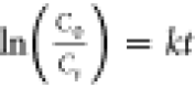 , where C0 is
the absorbance before the radiation and Ct is the absorbance after the applied radiation for time t.48Figure 7a shows the pollutant (methylene blue) before and after
irradiation every 30 min. The pollutant’s absorbance becomes
harmless as long as the irradiation is applied, which is more apparent
than the pollutant’s maximum absorption point. The percentage
of degradation is shown in Figure 7b, and the degradation rate constant is shown in Figure 7c,d. The degradation
of the pollutant by the semiconductor Fe2O3–carbon
increases with addition of AC in the composites. As shown in Figure 7b, for 25% AC, the
degradation reaches 89.51% only in 90 min, whereas other samples need
around 120 min to yield the harmless product. Figure 7c,d shows a plot of the
, where C0 is
the absorbance before the radiation and Ct is the absorbance after the applied radiation for time t.48Figure 7a shows the pollutant (methylene blue) before and after
irradiation every 30 min. The pollutant’s absorbance becomes
harmless as long as the irradiation is applied, which is more apparent
than the pollutant’s maximum absorption point. The percentage
of degradation is shown in Figure 7b, and the degradation rate constant is shown in Figure 7c,d. The degradation
of the pollutant by the semiconductor Fe2O3–carbon
increases with addition of AC in the composites. As shown in Figure 7b, for 25% AC, the
degradation reaches 89.51% only in 90 min, whereas other samples need
around 120 min to yield the harmless product. Figure 7c,d shows a plot of the  versus time degradation for all
samples,
where the slope is used for determining k and correlation
coefficient (R2) values, as shown in Table 3. The best performance
for the degradation indicated by the highest rate constant is for
the semiconductor Fe2O3–carbon with 25%
AC. This is due to the higher band gap with an additional carbon in
the semiconductor Fe2O3–carbon, suppressing
the recombination of the electron–hole pair when irradiated.48,89 A combination of C 1s from AC with Fe 3d and O 2p will facilitate
the generation of photo-induced electrons and suppress the recombination
of the charge (electron–hole) pairs; consequently, the photocatalytic
activity will increase.26,90,91 The increase of the carbon atom in the carbon-based magnetic materials
will significantly increase the photocatalytic activity due to the
destruction of the lattice, which is indicated by the decrease in
the magnetic crystalline anisotropy constant (K1) and the coercivity.92−94 The C 1s states at the valence
band edge increase with increasing carbon content based on the formula
C1–x(Fe2O3)x, which may suppress the recombination
of electron–hole pairs.
versus time degradation for all
samples,
where the slope is used for determining k and correlation
coefficient (R2) values, as shown in Table 3. The best performance
for the degradation indicated by the highest rate constant is for
the semiconductor Fe2O3–carbon with 25%
AC. This is due to the higher band gap with an additional carbon in
the semiconductor Fe2O3–carbon, suppressing
the recombination of the electron–hole pair when irradiated.48,89 A combination of C 1s from AC with Fe 3d and O 2p will facilitate
the generation of photo-induced electrons and suppress the recombination
of the charge (electron–hole) pairs; consequently, the photocatalytic
activity will increase.26,90,91 The increase of the carbon atom in the carbon-based magnetic materials
will significantly increase the photocatalytic activity due to the
destruction of the lattice, which is indicated by the decrease in
the magnetic crystalline anisotropy constant (K1) and the coercivity.92−94 The C 1s states at the valence
band edge increase with increasing carbon content based on the formula
C1–x(Fe2O3)x, which may suppress the recombination
of electron–hole pairs.
Figure 7.

(a) Absorbance from UV–vis spectra
and (b) degradation ability
determined from the equation  . The kinetic curve of the
photocatalytic
degradations (c) by
. The kinetic curve of the
photocatalytic
degradations (c) by  and (d)
  for Fe2O3–carbon
for various amounts of carbon (10, 15, 20, and 25% AC).
for Fe2O3–carbon
for various amounts of carbon (10, 15, 20, and 25% AC).
Less electron–hole recombination led to formation of more radical molecules and broke the pollutant bonding, thus yielding a harmless product.95 The electronic, magnetic, structural, optical, and photocatalytic properties of Fe2O3 can be tuned by adjusting the amount of carbon added, leading us to a promising multifunctional material for electromagnetic wave absorption/shielding and textile industry wastewater degradation. The novelty and photodegradation efficiency of this study compared with other references96−105 can clearly be seen in Table 5. The effect of AC concentration shows the highest efficiency as 93.76% for 20% AC but takes 120 min, compared with that of 25% AC, which is 89.51% but takes only 90 min.
Table 5. Comparison of the Synthesis Methods of the Materials and the Degradation Performance (%) of the Previously Reported Materials Containing Fe2O3 Doped with Various Materials-Based Photocatalysts with the Fe2O3–AC in this Study by the Simple Mechanical Alloying Method.
| type of photocatalyst | synthesis method | photocatalytic application | degradation performance | reference |
|---|---|---|---|---|
| FeS2/Fe2O3 | heat treatment | carbamazepine | 65% (by adding Cr (IV)) | Guo et al.96 |
| α-Fe2O3/rGO | heat treatment and ultrasound method | congo red | 60% | Wang et al.97 |
| Fe2O3/rGO | hummers method and Heat treatment | 4-nitrophenol | 98% | Sathish Mohan et al.98 |
| BiVO4/ α-Fe2O3 | in situ growth method | tetracycline | ∼75.8% | Ma et al.99 |
| Fe3N/Fe2O3/C3N4 | facile single-step preparation method | rhodamine B | 98% | Padervand et al.100 |
| KNbO3/α-Fe2O3 | hydrothermal/solvothermal route | methylene blue | 89% | Farooq et al.101 |
| Fe2O3/GO/WO3 | green method and ex situ method | phenol | 95.4% | Mohamed et al.102 |
| ZrO2/Fe2O3/RGO | hydrothermal route and Hummers method | congo red | 98.43% | Anjaneyulu et al.103 |
| ZnO/Fe2O3 | sol-gel method | metronidazole | 99% | Davari et al.104 |
| CuO/α-Fe2O3/γ-Al2O3 | facile wet chemical route | methylene orange | 98% | Kanwal et al.105 |
| Fe2O3/25%AC | simple mechanical alloying | methylene blue | 89.51 | present study |
| Fe2O3/20%AC | simple mechanical alloying | methylene blue | 93.76 | present study |
Figure 8 shows the relation of the structural (D), magnetic (Hc), and optical properties (Δ and band gap) with the degradation performance (Deg.) and reflection loss (RL) for attenuating the EM waves. The magnetic property and the Δ decrease with increase in the amount of carbon, but the ability to attenuate the EM waves (RL) in contrast to the band gap indicates that the carbon successfully acts as a net by covering Fe2O3. The photocatalytic activity takes 120 min to produce a harmless product for 10 to 20% AC, but 25% AC shows 89.5% degradation in just 90 min and shows the potential to attenuate the EM waves up to 99% due to the RL being below −20 dB. The second- and third-cycle degradation of the composite Fe2O3–AC for 25% AC are 88.2 and 86.5% in 90 min, respectively. This study shows the high potential of the composite Fe2O3–AC for multifunctional purposes, photocatalytic activity, and as a very good EM absorber for wave applications.
Figure 8.

Relation between the structural (D), magnetic (Hc), and optical properties (Δ and band gap) and the ability to attenuate the electromagnetic wave (RL) and the degradation performance (Deg.).
3. Conclusions
The semiconductor Fe2O3–carbon was used to successfully tune the structural, optical, band gap, and magnetic properties in the analyses by X-ray diffraction (XRD), Fourier transform infrared spectroscopy (FTIR), reflection electron energy loss spectroscopy (REELS), X-ray photoelectron spectroscopy (XPS), and a vibrating sample magnetometer (VSM), respectively. The EM wave absorption and removal of dye waste performance were analyzed using vector network analysis (VNA) and ultraviolet–visible (UV–vis) spectroscopy, respectively. The band gap linearly increased up to 2.64 eV by increasing the carbon content up to 25%, due to the interaction of C 1s with Fe 3d and O 2p affecting the top of the valence bands and making the band gap narrower in the form of C1–x(Fe2O3)x. These results increase the photon excitation energy, which contributes to the generation of electrons and holes, consequently increasing the absorption and degradation ability. The coercivity decreases on increasing the amount of AC due to the small atomic radii of the carbon inserted into the ferrite’s hexagonal structure. It creates a small wreck in the lattice, decreasing the K1 and Hc. The decrease in saturation magnetization occurs due to the nonmagnetic atoms of AC preferring to occupy the octahedral site of Fe ions rather than the O ions, leading to decreased MR and R, and increasing the local strain and exchange interactions at the octahedral sites. The best reflection loss is −21.43 dB at 5.54 GHz, and a degradation of up to 89.51% is achieved in only 90 min by 25% AC due to the higher band gap, which contributes to suppressing the recombination of the electrons and holes. These results indicate that the composite semiconductor Fe2O3–carbon from AC is a promising material for absorption of electromagnetic wave radiation and photodegradation of wastewater by tuning the structural, optical, and magnetic properties.
4. Experimental Section
Iron (III) oxide (Fe2O3) with a particle size of 50–100 nm and trace metals basis of 97% was purchased from Sigma Aldrich. Activated carbon (AC) with an average diameter of <10 μm, purity of >95%, and surface area of >240 m/g was purchased from PT. Cahaya Indo Abadi, Indonesia, and poly(vinyl alcohol) (PVA) with purity 99.5% was purchased from Merck.
The experimental procedure and the characterization system of XRD and FT-IR spectra were similar to those in the previous study.21,23,48,106 The magnetic studies were performed with a vibrating sample magnetometer (VSM) 1.2 H type from Oxford Instruments.20,23 The EM absorption was measured using a VNA (Vector Network Analyzer) (Rohde & Schwarz ZVHB) with the frequency range from 2.5 to 8 GHz, and the absorbance for every 30 min of irradiation was measured from the UV–vis (ultraviolet–visible) spectra (Shimadzu UV–vis Spectrophotometer UV-1800).20,21,23,30 The characterization by REELS was similar to that in our previous paper.20,23
For photocatalytic activity, the radiation source was a halogen lamp (300 W, OSRAM 645, Germany) and the measurement was done every 30 min. The pellet samples were suspended in 50 mL of methylene blue with a concentration of 1 × 10⁻⁵ M, and the distance from the halogen lamps was about 30 cm. The absorption spectra were recorded using an ultraviolet–visible (UV–vis) spectrophotometer, Shimadzu UV-1800.48
Acknowledgments
This work was supported by the PT (Penelitian Terapan) 2021 grant 752/UN4.22/PT.01.03/2021 funded by the DIKTI/BRIN, Indonesia.
The authors declare no competing financial interest.
References
- Jayanth B. V.; Prathap P.; Sivaraman P.; Yogesh S.; Madhu S. Implementation of lean manufacturing in electronics industry. Mater. Today: Proc. 2020, 33, 23–28. 10.1016/j.matpr.2020.02.718. [DOI] [Google Scholar]
- Raj-Reichert G. Exercising power over labour governance in the electronics industry. Geoforum. 2015, 67, 89–92. 10.1016/j.geoforum.2015.10.013. [DOI] [Google Scholar]
- de Oliveira Neto G. C.; Correia J. M. F.; Silva P. C.; de Oliveira Sanche A. G.; Lucato W. S. Cleaner Production in the textile industry and its relationship to sustainable development goals. J. Cleaner Prod. 2019, 228, 1514–1525. 10.1016/j.jclepro.2019.04.334. [DOI] [Google Scholar]
- Núñez J.; Yeber M.; Cisternas N.; Thibaut R.; Medina P.; Carrasco C. Application ofelectrocoagulation for the efficient pollutants removal to reuse the treated wastewater in the dyeing process of the textile industry. J. Hazard. Mater. 2019, 371, 705–711. 10.1016/j.jhazmat.2019.03.030. [DOI] [PubMed] [Google Scholar]
- Reddy N.; Chen L.; Zhang Y.; Yang Y. Reducing environmental pollution of the textile industry using keratin as alternative sizing agent to poly(vinyl alcohol). J. Cleaner Prod. 2014, 65, 561–567. 10.1016/j.jclepro.2013.09.046. [DOI] [Google Scholar]
- Jiang Q.; Chen S.; Deng X.; Feng Y.; Reddy N.; Zhu Q.; Liu W.; Qiu Y. A sustainable low temperature yarn reinforcing process to reduce water and energy consumptions and pollution in the textile industry. J. Cleaner Prod. 2019, 210, 646–652. 10.1016/j.jclepro.2018.11.034. [DOI] [Google Scholar]
- Liang J.; Ning X.; Sun J.; Song J.; Lu J.; Cai H.; Hong Y. Toxicity evaluation of textile dyeing effluent and its possible relationship with chemical oxygen demand. Ecotoxicol. Environ. Saf. 2018, 166, 56–62. 10.1016/j.ecoenv.2018.08.106. [DOI] [PubMed] [Google Scholar]
- Singh V.; Srivastava V. C. Self-engineered iron oxide nanoparticle incorporated on mesoporous biochar derived from textile mill sludge for the removal of an emerging pharmaceutical pollutant. Environ. Pollut. 2020, 259, 113822 10.1016/j.envpol.2019.113822. [DOI] [PubMed] [Google Scholar]
- Tounsadi H.; Metarfi Y.; Taleb M.; Rhazi K. E.; Rais Z. Impact of chemical substances used in textile industry on the employee’s health: Epidemiological study. Ecotoxicol. Environ. Saf. 2020, 197, 110594 10.1016/j.ecoenv.2020.110594. [DOI] [PubMed] [Google Scholar]
- GilPavas E.; Correa-Sânchez S.; Acosta D. A. Using scrap zero valent iron to replace dissolved iron in the Fentonprocess for textile wastewater treatment: Optimization and assessment of toxicity and biodegradability. Environ. Pollut. 2019, 252, 1709–1718. 10.1016/j.envpol.2019.06.104. [DOI] [PubMed] [Google Scholar]
- Rasalingam S.; Peng R.; Koodali R. T. Removal of Hazardous Pollutants from Wastewaters: Applications of TiO2-SiO2 Mixed Oxide Materials. J. Nanomater. 2014, 2014, 617405 10.1155/2014/617405. [DOI] [Google Scholar]
- Meshesha T. W.; Wang J.; Melaku N. D. Modelling spatiotemporal patterns of water quality and its impacts on aquatic ecosystem in the cold climate region of Alberta, Canada. J. Hydrol. 2020, 587, 124952 10.1016/j.jhydrol.2020.124952. [DOI] [Google Scholar]
- Elfsmark L.; Ågren L.; Akfur C.; Bucht A.; Jonasson S. 8-Isoprostane is an early biomarker for oxidative stress in chlorine-induced acute lung injury. Toxicol. Lett. 2018, 282, 1–7. 10.1016/j.toxlet.2017.10.007. [DOI] [PubMed] [Google Scholar]
- Hoyle G. W.; Chen J.; Schlueter C. F.; Mo Y.; Humphrey D. M. jr; Rawson G.; Niño J. A.; Carson K. H. Development and assessment of countermeasure formulations for treatment of lung injury induced by chlorine inhalation. Toxicol. Appl. Pharmacol. 2016, 298, 9–18. 10.1016/j.taap.2016.03.001. [DOI] [PMC free article] [PubMed] [Google Scholar]
- Tyan K.; Kang J.; Jin K.; Kyle A. M. Evaluation of the antimicrobial efficacy and skin safety of a novel color additive in combination with chlorine disinfectants. Am. J. Infect. Control 2018, 46, 1254–1261. 10.1016/j.ajic.2018.04.223. [DOI] [PMC free article] [PubMed] [Google Scholar]
- Nemery B.; Hoet P. H. M.; Nowak D. Indoor swimming pools, water chlorination and respiratory health. Eur. Respir. J. 2002, 19, 790–793. 10.1183/09031936.02.00308602. [DOI] [PubMed] [Google Scholar]
- Zhu Z.; Guo Y.; Yu P.; Wang X.; Zhang X.; Dong W.; Liu X.; Guo C. Chlorine dioxide inhibits the replication of porcine reproductive and respiratory syndrome virus by blocking viral attachment. Infect., Genet. Evol. 2019, 67, 78–87. 10.1016/j.meegid.2018.11.002. [DOI] [PubMed] [Google Scholar]
- Gomà A.; Lluis Rd.; Roca-Ferrer J.; Lafuente J.; Picado C. Respiratory, Respiratory, ocular and skin health in recreational and competitive swimmers: Beneficial effect of a new method to reduce chlorine oxidant derivatives. Environ. Res. 2017, 152, 315–321. 10.1016/j.envres.2016.10.030. [DOI] [PubMed] [Google Scholar]
- Wiergowski M.; Sołtyszewski I.; Anand J. S.; Kaliszan M.; Wilmanowska J. A.; Jankowski Z.; Łukasik M. Difficulties in interpretation when assessing prolonged and subacute exposure to the toxic effects of chlorine. J. Forensic Leg. Med. 2018, 58, 82–86. 10.1016/j.jflm.2018.05.003. [DOI] [PubMed] [Google Scholar]
- Tahir D.; Ilyas S.; Abdullah B.; Armynah B.; Kang H. J. Electronic properties of composite iron (II, III) oxide (Fe3O4) carbonaceous absorber materials by electron spectroscopy. J. Electron Spectrosc. Relat. Phenom. 2018, 229, 47–51. 10.1016/j.elspec.2018.09.008. [DOI] [Google Scholar]
- Abdullah B.; Ilyas S.; Tahir D. Nanocomposites Fe/activated carbon/PVA for microwave absorber: synthesis and characterization. J. Nanomater. 2018, 2018, 9823263 10.1155/2018/9823263. [DOI] [Google Scholar]
- Abdullah B.; Nisyah A.; Ilyas S.; Tahir D. Structural properties and bonding characteristics of honeycomb structure of composite ZnMnO2 and activated carbon. J. Appl. Biomater. Funct. Mater. 2019, 17, 228080001882018 10.1177/2280800018820185. [DOI] [PubMed] [Google Scholar]
- Tahir D.; Ilyas S.; Abdullah B.; Armynah B.; Kim K.; Kang H. J. Modification in electronic, structural, and magnetic properties based on composition of composites Copper (II) Oxide (CuO) and Carbonaceous material. Mater. Res. Express 2019, 6, 035705 10.1088/2053-1591/aaf7da. [DOI] [Google Scholar]
- Hendri; Abdullah B.; Tahir D.; Fatimah S. New types composite copper (Cu) and activated carbon (C) for electromagnetic wave absorber materials. J. Phys.: Conf. Ser. 2019, 1242, 012031 10.1088/1742-6596/1242/1/012031. [DOI] [Google Scholar]
- Tahir D.; Kraaer J.; Tougaard S. Electronic and optical properties of Fe, Pd, and Ti studied by reflection electron energy loss spectroscopy. J. Appl. Phys. 2014, 115, 243508 10.1063/1.4885876. [DOI] [Google Scholar]
- Tahir D.; Oh S. K.; Kang H. J.; Tougaard S. Quantitative analysis of reflection electron energy loss spectra to determine electronic and optical properties of Fe-Ni alloy thin films. J. Electron Spectrosc. Relat. Phenom. 2016, 206, 6–18. 10.1016/j.elspec.2015.11.005. [DOI] [Google Scholar]
- Popov V.; Shevchenko A. Analysis of standards and norms of electromagnetic irradiation levels in wireless communication systems on railway transport. Procedia Comput. Sci. 2019, 149, 239–245. 10.1016/j.procs.2019.01.129. [DOI] [Google Scholar]
- Piro G.; Bia P.; Boggia G.; Caratelli D.; Grieco L. A.; Mescia L. Terahertz electromagnetic field propagation in human tissues: A study on communication capabilities. Nano Commun. Networks 2016, 10, 51–59. 10.1016/j.nancom.2016.07.010. [DOI] [Google Scholar]
- Ahlbom A.; Bridges J.; de Seze R.; Hillert L.; Juutilainen J.; Mattsson M.; Neubauer G.; Schűz J.; Simko M.; Bromen K. Possible effects of electromagnetic fields (EMF) on human health-Opinion of the Scientific Committee on Emerging and Newly Identified Health Risks (SCENIHR). Toxicology 2008, 246, 248–250. 10.1016/j.tox.2008.02.004. [DOI] [PubMed] [Google Scholar]
- Ilyas S.; Heryanto H.; Abdullah B.; Tahir D. X-Ray Diffraction Analysis of Nanocomposite Fe3O4/Activated Carbon by Williamson-Hall and Size-Strain Plot Methods. Nano-Struct. Nano-Objects 2019, 20, 100396 10.1016/j.nanoso.2019.100396. [DOI] [Google Scholar]
- Heryanto H.; Abdullah B.; Tahir D. Quantitative analysis of X-Ray diffraction spectra for determine structural properties and deformation energy of Al, Cu and Si. J. Phys.: Conf. Ser. 2018, 979, 012055 10.1088/1742-6596/979/1/012055. [DOI] [Google Scholar]
- Heryanto H.; Abdullah B.; Tahir D. Analysis of structure properties of X-ray diffraction for composite copper-activated carbon by modified Williamson-Hall and size-strain plotting methods. J. Phys.: Conf. Ser. 2018, 1080, 012007 10.1088/1742-6596/1080/1/012007. [DOI] [Google Scholar]
- Bendjebbar K.; Rahal W. L.; Racheda D.; Bahlouli S. Numerical analysis of metal-semiconductor junctions ITO/p-a-Si:H and n-c-Si/Al on silicon heterojunction solar cells. Optik 2020, 212, 164741 10.1016/j.ijleo.2020.164741. [DOI] [Google Scholar]
- Liu Y.; Yang B.; Zhang M.; Xia B.; Chen C.; Liu X.; Zhong J.; Xiao Z.; Tang J. Bournonite CuPbSbS3: An electronically-3D, defect-tolerant, and solution-processable semiconductor for efficient solar cells. Nano Energy 2020, 71, 104574 10.1016/j.nanoen.2020.104574. [DOI] [Google Scholar]
- Lukin L. V. Electric polarization of electron-hole pairs in organic semiconductors induced by picosecond pulses of an electromagnetic wave: Consideration of small-molecule semiconductors with a negligibly small concentration of traps. Chem. Phys. 2019, 527, 110456 10.1016/j.chemphys.2019.110456. [DOI] [Google Scholar]
- Kannan K.; Radhika D.; Sadasivuni K. K.; Reddy K. R.; Raghu A. V. Nanostructured metal oxides and its hybrids for biomedical applications. Adv. Colloid Interface Sci. 2020, 281, 102178 10.1016/j.cis.2020.102178. [DOI] [PubMed] [Google Scholar]
- Yin Y.; Zhang X.; Sun C. Transition-metal-doped Fe2O3 nanoparticles for oxygen evolution reaction. Prog. Nat. Sci.: Mater. Int. 2018, 28, 430–436. 10.1016/j.pnsc.2018.07.005. [DOI] [Google Scholar]
- Mishra M.; Chun D. α-Fe2O3 as a photocatalytic material: A review. Appl. Catal., A 2015, 498, 126–141. 10.1016/j.apcata.2015.03.023. [DOI] [Google Scholar]
- Tahir D.; Tougaard S. Electronic and optical properties of Cu, CuO and Cu2O studied by electron spectroscopy. J. Phys.: Condens. Matter 2012, 24, 175002 10.1088/0953-8984/24/17/175002. [DOI] [PubMed] [Google Scholar]
- do Amaral Junior M.A.; Marcuzzo J. S.; da Silva Pinheiro B.; Lopes B. H. K.; de Oliveira A.P.S.; Matsushima J. T.; Baldan M. R. Study of reflection process for nickel coated activated carbon fiber felt applied with electromagnetic interference shielding. J. Mater. Res. Technol. 2019, 8, 4040–4047. 10.1016/j.jmrt.2019.07.014. [DOI] [Google Scholar]
- Tahir D.; Oh S. K.; Kang H. J.; Tougaard S. Composition Dependence of Dielectric and Optical Properties of Hf-Zr-Silicate Thin Films Grown on Si (100) by Atomic Layer Deposition. Thin Solid Films 2016, 616, 425–430. 10.1016/j.tsf.2016.09.001. [DOI] [Google Scholar]
- Köse K.Ö.; Piskin B.; Aydınol M. K. Chemical and structural optimization of ZnCl2activated carbons via high temperature CO2 treatment for EDLC applications. Int. J. Hydrogen Energy 2018, 43, 18607–18616. 10.1016/j.ijhydene.2018.03.222. [DOI] [Google Scholar]
- Sahu A.; Sen S.; Mishra S. C. Economical way of processing activated carbon from Calotropisgigantea and its suitability for application in Lithium/Sodium ion batteries. Diamond Relat. Mater. 2020, 108, 107931 10.1016/j.diamond.2020.107931. [DOI] [Google Scholar]
- Ukkakimapan P.; Sattayarut V.; Wanchaem T.; Yordsri V.; Phonyiem M.; Ichikawa S.; Obata M.; Fujishige M.; Takeuchi K.; Wongwiriyapan W.; Endo M. Preparation of activated carbon via acidic dehydration of durian husk for supercapacitor applications. Diamond Relat. Mater 2020, 107, 107906 10.1016/j.diamond.2020.107906. [DOI] [Google Scholar]
- Patra C.; Gupta R.; Bedadeep D.; Narayanasamy S. Surface treated acid-activated carbon for adsorption of anionic azo dyes from single and binary adsorptive systems: A detail insight. Environ. Pollut. 2020, 266, 115102 10.1016/j.envpol.2020.115102. [DOI] [PubMed] [Google Scholar]
- Li J.; Xing X.; Li J.; Shi M.; Lin A.; Xu C.; et al. Preparation of thiol-functionalized activated carbon from sewage sludge with coal blending for heavy metal removal from contaminated water. Environ. Pollut. 2018, 234, 677–683. 10.1016/j.envpol.2017.11.102. [DOI] [PubMed] [Google Scholar]
- Tahir D.; Heryanto H.; Ilyas S.; Fahri A. N.; Rahmat R.; Rahmi M. H.; Taryana Y.; Sukaryo S. G. Excellent electromagnetic wave absorption Co/Fe2O3 composites by additional activated carbon for tuning the optical and the magnetic properties. J. Alloys Compd. 2021, 864, 158780 10.1016/j.jallcom.2021.158780. [DOI] [Google Scholar]
- Ilyas S.; Abdullah B.; Tahir D. Enhancement of Absorbing Frequency and Photo-Catalytic Performance by Temperature Treatment of Composites Fe3O4-AC Nanoparticle. Adv. Powder Technol. 2020, 31, 905–913. 10.1016/j.apt.2019.11.007. [DOI] [Google Scholar]
- Tahir D.; Tougaard S. Electronic and optical properties of selected polymers studied by reflection electron energy loss spectroscopy. J. Appl. Phys. 2012, 111, 054101 10.1063/1.3688327. [DOI] [Google Scholar]
- Tahir D.; Kwon H. L.; Shin H. C.; Oh S. K.; Kang H. J.; Heo S.; Chung J. G.; Lee J. C.; Tougaard S. Electronic and optical properties of Al2O3/SiO2 thin films grown on Si substrate. J. Phys. D: Appl. Phys. 2010, 43, 255301 10.1088/0022-3727/43/25/255301. [DOI] [Google Scholar]
- Tahir D.; Choi E. H.; Cho Y. J.; Oh S. K.; Kang H. J.; Jin H.; Heo S.; Chung J. G.; Lee J. C.; Tougaard S. Electronic and optical properties of La-aluminate dielectric thin films on Si (100). Surf. Interface Anal. 2010, 42, 1566–1569. 10.1002/sia.3590. [DOI] [Google Scholar]
- Suryani S.; Heryanto H.; Rusdaeni R.; Fahri A. N.; Tahir D. Quantitative analysis of diffraction and infra-red spectra of composite cement/BaSO4/Fe3O4 for determining correlation between attenuation coefficient, structural and optical properties. Ceram. Int. 2020, 46, 18601–18607. 10.1016/j.ceramint.2020.04.170. [DOI] [Google Scholar]
- Nurhasmi H.; Heryanto H.; Fahri A. N.; Ilyas S.; Ansar A.; Abdullah B.; Tahir D. Study on Optical Phonon Vibration and Gamma Ray Shielding Properties of Composite Geopolymer Fly-Ash-Metal. Radiat. Phys. Chem. 2021, 180, 109250 10.1016/j.radphyschem.2020.109250. [DOI] [Google Scholar]
- Rauf N.; Ilyas S.; Heryanto H.; Rahmat R.; Fahri A. N.; Rahmi M. H.; Tahir D. The Correlation between Structural and Optical Properties of Zinc Hydroxide Nanoparticle in Supports Photocatalytic Performance. Opt. Mater. 2021, 112, 110780 10.1016/j.optmat.2020.110780. [DOI] [Google Scholar]
- Lahsmin Y. K.; Heryanto H.; Ilyas S.; Fahri A. N.; Abdullah B.; Tahir D. Optical properties determined from infrared spectroscopy and structural properties from diffraction spectroscopy of composites Fe/CNs/PVA for electromagnetic wave absorption. Opt. Mater. 2021, 111, 110639 10.1016/j.optmat.2020.110639. [DOI] [Google Scholar]
- Jangong O. S.; Heryanto H.; Rahmat R.; Mutaminna I.; Gareso P. L.; Tahir D. Effect of Sugar Palm Fiber (SPF) to the Structural and Optical Properties of Bioplastics (SPF/Starch/Chitosan/Polypropylene) in supporting Mechanical Properties and Degradation Performance. J. Polym. Environ. 2021, 1694–1705. 10.1007/s10924-020-02019-9. [DOI] [Google Scholar]
- Ulum B.; Ilyas S.; Fahri A. N.; Mutmainna I.; Anugrah M. A.; Yudasari N.; Demmalino E. B.; Tahir D. Composite Carbon-lignin/ Zinc Oxide Nanocrystalline Ball-like Hexagonal Mediated from Jatropha curcas L Leaf as Photocatalyst for Industrial Dye Degradation. J. Inorg. Organomet. Polym. Mater. 2020, 30, 4905–4916. 10.1007/s10904-020-01631-5. [DOI] [Google Scholar]
- Tahir D.; Park N. S.; Yang D. S.; Kang H. J. Electronic properties of Ga-In-Zn-O (GIZO) thin films: Effect of post-annealing. J. Electron Spectrosc. Relat. Phenom. 2020, 30, 4905–4916. [Google Scholar]
- Liu H.; Luo S.; Hu D.; Liu X.; Wang Q.; Wang Z.; Wang Y.; Chang L.; Liu Y.; Yi T.; Zhang Y.; Hao A. Design and synthesis of carbon-coated α-Fe2O3@Fe3O4 heterostructured as anode materials for lithium-ion batteries. Appl. Surf. Sci. 2019, 495, 143590 10.1016/j.apsusc.2019.143590. [DOI] [Google Scholar]
- Uvarov V.; Popov I. Metrological characterization of X-ray diffraction methods at different acquisition geometries for determination of crystallite size in nano-scale materials. Mater. Charact. 2013, 85, 111–123. 10.1016/j.matchar.2013.09.002. [DOI] [Google Scholar]
- Gonçalves N. S.; Carvalho J. A.; Lima Z. M.; Sasaki J. M. Size–strain study of NiO nanoparticles by X-ray powder diffraction line broadening. Mater. Lett. 2012, 72, 36–38. 10.1016/j.matlet.2011.12.046. [DOI] [Google Scholar]
- Chandekar K. V.; Kant K. M. Size-strain analysis and elastic properties of CoFe2O4 nanoplatelets by hydrothermal method. J. Mol. Struct. 2018, 1154, 418–427. 10.1016/j.molstruc.2017.09.104. [DOI] [Google Scholar]
- Heryanto H.; Abdullah B.; Tahir D.; Mahdalia M. Quantitative analysis of X-Ray diffraction spectra for determine structural properties and deformation energy of Al, Cu and Si. J. Phys.: Conf. Ser. 2019, 1317, 012052 10.1088/1742-6596/1317/1/012052. [DOI] [Google Scholar]
- Singh D. P.; Singh G. P. Conversion of covalent to ionic behavior of Fe2O3–CeO2–PbO–B2O3 glasses for ionic and photonic application. J. Alloys Compd. 2013, 546, 224–228. 10.1016/j.jallcom.2012.08.105. [DOI] [Google Scholar]
- Nath D.; Singh F.; Das R. X-ray diffraction analysis by Williamson-Hall, Halder-Wagner and size-strain plot methods of CdSe nanoparticles- a comparative study. Mater. Chem. Phys. 2020, 239, 122021 10.1016/j.matchemphys.2019.122021. [DOI] [Google Scholar]
- Sundaram P. S.; Sangeetha T.; Rajakarthihan S.; Vijayalaksmi R.; Elangovan A.; Arivazhagan G. XRD structural studies on cobalt doped zinc oxide nanoparticles synthesized by coprecipitation method: Williamson-Hall and size-strain plot approaches. Phys. B 2020, 595, 412342 10.1016/j.physb.2020.412342. [DOI] [Google Scholar]
- Rani N.; Chahal S.; Chauhan A. S.; Kumar P.; Shukla R.; Singh S. K. X-ray Analysis of MgO Nanoparticles by Modified Scherer’s Williamson-Hall and Size-Strain Method. Mater. Today: Proc. 2019, 12, 543–548. 10.1016/j.matpr.2019.03.096. [DOI] [Google Scholar]
- Florez R.; Colorado H. A.; Alajo A.; Giraldo C. H. C. The material characterization and gamma attenuation properties of Portland cement-Fe3O4 composites for potential dry cask applications. Prog. Nucl. Energy 2019, 111, 65–73. 10.1016/j.pnucene.2018.10.022. [DOI] [Google Scholar]
- Dadras S.; Davoudiniya M. Analysis of YBCO high temperature superconductor doped with silver nanoparticles and carbon nanotubes using Williamson-Hall and Size-Strain Plot. Phys. C 2018, 548, 116–118. 10.1016/j.physc.2018.02.022. [DOI] [Google Scholar]
- Rajesh Kumar B.; Hymavathi B. X-ray peak profile analysis of solid-state sintered alumina doped zinc oxide ceramics by Williamson–Hall and size-strain plot methods. J. Asian Ceram. Soc. 2017, 5, 94–103. 10.1016/j.jascer.2017.02.001. [DOI] [Google Scholar]
- Khorrami Gh. H.; Zak A. K.; Kompany A.; Yousefi R. Optical and structural properties of X-doped (X = Mn, Mg, and Zn) PZT nanoparticles by Kramers–Kronig and size strain plot methods. Ceram. Int. 2012, 38, 5683–5690. 10.1016/j.ceramint.2012.04.012. [DOI] [Google Scholar]
- Li Y.; Qiu W.; Qin F.; Fang H.; Hadjiev V. G.; Litvinov D.; Bao J. Identification of Cobalt Oxides with Raman Scattering and Fourier Transform Infrared Spectroscopy. J. Phys. Chem. C 2016, 120, 4511–4516. 10.1021/acs.jpcc.5b11185. [DOI] [Google Scholar]
- Ghasemifard M.; Hosseini S. M.; Khorrami Gh. H. Synthesis and structure of PMN–PT ceramic nanopowder free from pyrochlore phase. Ceram. Int. 2009, 35, 2899–2905. 10.1016/j.ceramint.2009.03.036. [DOI] [Google Scholar]
- Zamiri R.; Chenari H. M.; Moafi H. F.; Shabani M.; Salehizadeh S. A.; Rebelo A.; Kumar J. S.; Graça M. P. F.; Soares M. J.; Ferreira J. M. F. Ba-doped ZnO nanostructure: X-ray line analysis and optical properties in visible and low frequency infrared. Ceram. Int. 2016, 42, 12860–12867. 10.1016/j.ceramint.2016.05.051. [DOI] [Google Scholar]
- Legan L.; Leskovar T.; Ĉreŝnar M.; Cavalli F.; Innocenti D.; Ropret P. Non-invasive reflection FTIR characterization of archaeological burntbones: Reference database and case studies. J. Cult. Herit. 2020, 41, 13–26. 10.1016/j.culher.2019.07.006. [DOI] [Google Scholar]
- Hardoň Š.; Kúdelčík J.; Jahoda E.; Kúdelĉíková M. The Magneto-Dielectric Anisotropy Effect in the Oil-Based Ferrofluid. Int. J. Thermophys. 2019, 40, 24 10.1007/s10765-019-2486-4. [DOI] [Google Scholar]
- Lu X.; Chen J.; Zheng M.; Guo J.; Qi J.; Chen Y.; Miao S.; Zheng B. Effect of high-intensity ultrasound irradiation on the stability and structuralfeatures of coconut-grain milk composite systems utilizing maize kernels and starch with different amylose contents. Ultrason. Sonochem. 2019, 55, 135–148. 10.1016/j.ultsonch.2019.03.003. [DOI] [PubMed] [Google Scholar]
- Ghasemifard M.; Fathi E.; Ghamari M. The effect of Fe3+-doped on structure and optical properties of mesoporous Al2O3/SiO2 composite. Mater. Sci. Semicond. Process. 2016, 42, 349–353. 10.1016/j.mssp.2015.11.001. [DOI] [Google Scholar]
- Shin H. C.; Tahir D.; Seo S.; Denny Y. R.; Oh S. K.; Kang H. J.; Heo S.; Chung J. G.; Lee J. C.; Tougaard S. Reflection electron energy loss spectroscopy for ultrathin gate oxide materials. Surf. Interface Anal. 2012, 44, 623–627. 10.1002/sia.3861. [DOI] [Google Scholar]
- Suryani S.; Heryanto H.; Tahir D. Stopping powers and inelastic mean free path from quantitative analysis of experimental REELS spectra for electrons in Ti, Fe, Ni, and Pd. Surf. Interface Anal. 2020, 52, 16–22. 10.1002/sia.6713. [DOI] [Google Scholar]
- Kang X.; Liu S.; Dai Z.; He Y.; Song X.; Tan Z. Titanium Dioxide: From Engineering to Applications. Catalysts 2019, 9, 191. 10.3390/catal9020191. [DOI] [Google Scholar]
- Wang F.; Li Q.; Xu D. Recent Progress in Semiconductor-Based Nanocomposite Photocatalysts for Solar-to-Chemical Energy Conversion. Adv. Energy Mater 2017, 7, 1700529 10.1002/aenm.201700529. [DOI] [Google Scholar]
- Yousuf M. A.; Jabeen S.; Shahi M. N.; Khan M. A.; Shakir I.; Warsi M. F. Magnetic and electrical properties of yttrium substituted manganese ferrite nanoparticles prepared via micro-emulsion route. Results Phys. 2020, 16, 102973 10.1016/j.rinp.2020.102973. [DOI] [Google Scholar]
- Shahbaz M.; Sadiq I.; Butt M. M. H.; Javaid A. B.; Idrees M.; Hussain S.; Sadiq F.; Riaz S.; Naseem S.; Khan H. M. Peculiar magnetic behavior and structural, electrical, dielectric properties of substituted R-type hexagonal ferrites. J. Magn. Magn. Mater 2020, 499, 166309 10.1016/j.jmmm.2019.166309. [DOI] [Google Scholar]
- Sahoo B.; Devi K. S. P.; Dutta S.; Maiti T. K.; Pramanik P.; Dhara D. Biocompatible mesoporous silica-coated superparamagnetic manganese ferrite nanoparticles for targeted drug delivery and MR imaging applications. J. Colloid Interface Sci. 2014, 431, 31–41. 10.1016/j.jcis.2014.06.003. [DOI] [PubMed] [Google Scholar]
- Ibrahim E. M. M.; Abdel-Rahman L. H.; Abu-Dief A. M.; Elshafaie A.; Hamdan S. K.; Ahmed A. M. Electric, thermoelectric and magnetic characterization of γ-Fe2O3 and Co3O4 nanoparticles synthesized by facile thermal decomposition of metal-Schiff base complexes. Mater. Res. Bull 2018, 99, 103–108. 10.1016/j.materresbull.2017.11.002. [DOI] [Google Scholar]
- Ouachtak H.; Haouti R. E.; Guerdaoui A. E.; Haounati R.; Amaterz E.; Addi A. A.; Akbal F.; Taha M. L. Experimental and molecular dynamics simulation study on the adsorption of Rhodamine B dye on magnetic montmorillonite composite γ-Fe2O3@Mt.. J. Mol. Liq. 2020, 309, 113142 10.1016/j.molliq.2020.113142. [DOI] [Google Scholar]
- Chen W.; Zhang Z.; Bao W.; Lai Y.; Li J.; Gan Y.; Wang J. Hierarchical mesoporous γ-Fe2O3/carbon nanocomposites derived from metal organic frameworks as a cathode electrocatalyst for rechargeable Li-O2 batteries. Electrochim. Acta 2014, 134, 293–301. 10.1016/j.electacta.2014.04.110. [DOI] [Google Scholar]
- Sonu; Dutta V.; Sharma S.; Raizada P.; Hosseini-Bandegharaei A.; Gupta V. K.; Singh P. Review on augmentation in photocatalytic activityof CoFe2O4 via heterojunction formation for photocatalysis of organic pollutants in water. J. Saudi Chem. Soc. 2019, 23, 1119–1136. 10.1016/j.jscs.2019.07.003. [DOI] [Google Scholar]
- Ravichandran K.; Chidhambaram N.; Arun T.; Velmathi S.; Gobalakrishnan S. Realizing cost-effective ZnO:Sr nanoparticles@graphene nanospreads for improved photocatalytic and antibacterial activities. RSC Adv. 2016, 6, 67575–67585. 10.1039/C6RA08697G. [DOI] [Google Scholar]
- Shaker-Agjekandy S.; Habibi-Yangjeh A. Ultrasonic-assisted preparation of novel ternary ZnO/AgI/Ag2CrO4 nanocomposites as visible-light-driven photocatalysts with excellent activity. Mater. Sci. Semicond. Process. 2016, 44, 48–56. 10.1016/j.mssp.2015.12.025. [DOI] [PubMed] [Google Scholar]
- Xie Z.; Feng Y.; Wang F.; Chen D.; Zhang Q.; Zeng Y.; Liu W.; Lv G. Construction of carbon dots modified MoO3/g-C3N4 Z-scheme photocatalyst with enhanced visible-light photocatalytic activity for the degradation of tetracycline. Appl. Catal., B. 2018, 229, 96–104. 10.1016/j.apcatb.2018.02.011. [DOI] [Google Scholar]
- Raizada P.; Kumari J.; Shandilya P.; Dhiman R.; Singh V. P.; Singh P. Magnetically retrievable Bi2WO6/Fe3O4 immobilized on graphene sand composite for investigation of photocatalytic mineralization of oxytetracycline and ampicillin. Process Saf. Environ. Prot. 2017, 106, 104–116. 10.1016/j.psep.2016.12.012. [DOI] [Google Scholar]
- Sudhaik A.; Raizada P.; Shandilya P.; Singh P. Magnetically recoverable graphitic carbon nitride and NiFe2O4 based magnetic photocatalyst for degradation of oxytetracycline antibiotic in simulated wastewater under solar light. J. Environ. Chem. Eng. 2018, 6, 3874–3883. 10.1016/j.jece.2018.05.039. [DOI] [Google Scholar]
- Singh P.; Shandilya P.; Raizada P.; Sudhaik A.; Rahmani-Sani A.; Hosseini-Bandegharaei A. Review on various strategies for enhancing photocatalytic activity of graphene based nanocomposites for water purification. Arab. J. Chem. 2020, 13, 3498–3520. 10.1016/j.arabjc.2018.12.001. [DOI] [Google Scholar]
- Guo Q.; Tang G.; Zhu W.; Luo Y.; Gao X. In situ construction of Z-scheme FeS2/Fe2O3 photocatalyst via structural transformation of pyrite for photocatalytic degradation of carbamazepine and the synergistic reduction of Cr(IV). J. Environ. Sci. 2021, 101, 351–360. 10.1016/j.jes.2020.08.029. [DOI] [PubMed] [Google Scholar]
- Wang Y.; Wang S.; Wu Y.; Wang Z.; Zhang H.; Cao Z.; He J.; Li W.; Yang Z.; Zheng L.; Feng D.; Pan P.; Bi J.; Li H.; Zhao J.; Zhang K. A α-Fe2O3/rGO magnetic photocatalyst: Enhanced photocatalytic performance regulated by magnetic field. J. Alloys Compd. 2021, 851, 156733 10.1016/j.jallcom.2020.156733. [DOI] [Google Scholar]
- Mohan B. S.; Ravi K.; Anjaneyulu B. R.; Sree G. S.; Basavaiah K. Fe2O3/rGO nanocomposite photocatalyst: Effective degradation of 4-Nitrophenol. Phys. B 2019, 553, 190–194. 10.1016/j.physb.2018.10.033. [DOI] [Google Scholar]
- Ma C.; Lee J.; Kim Y.; Seo W. C.; Jung H.; Yang W. Rational design of α-Fe2O3 nanocubes supported BiVO4 Z-scheme photocatalyst for photocatalytic degradation of antibiotic under visible light. J. Colloid Interface Sci 2021, 581, 514–522. 10.1016/j.jcis.2020.07.127. [DOI] [PubMed] [Google Scholar]
- Padervand M.; Rhimi B.; Wang C. One-pot synthesis of novel ternary Fe3N/Fe2O3/C3N4 photocatalyst for efficient removal of rhomanine B and CO2 reduction. J. Alloys Compd. 2021, 852, 156955 10.1016/j.jallcom.2020.156955. [DOI] [Google Scholar]
- Farooq U.; Chaudhary P.; Ingole P. P.; Kalam A.; Ahmad T. Development of cuboidal KNbO3@α-Fe2O3 hybrid nanostructures for improved photocatalytic and photoelectrocatalytic application. ACS Omega 2020, 5, 20491–20505. 10.1021/acsomega.0c02646. [DOI] [PMC free article] [PubMed] [Google Scholar]
- Mohamed H. H. Rationally design Fe2O3/GO/WO3 Z-scheme photocatalyst for enhanced solar light photocatalytic water remediation. J. Photochem. Photobiol., A 2019, 378, 74–84. 10.1016/j.jphotochem.2019.04.023. [DOI] [Google Scholar]
- Anjaneyulu R. B.; Mohan B. S.; Naidu G. P.; Muralikhlisna R. ZrO2/Fe2O3/rGO nanocomposite: Good photocatalyst for dyes degradation. Phys. E 2019, 108, 105–111. 10.1016/j.physe.2018.12.007. [DOI] [Google Scholar]
- Davari N.; Farhadian M.; Nazar A. R. S. Synthesis and characterization of Fe2O3 doped ZnO supported on clinoptilolite for photocatalytic degradation of metronidazole. Environ. Technol. 2021, 42, 1734–1746. 10.1080/09593330.2019.1680738. [DOI] [PubMed] [Google Scholar]
- Kanwal A.; Sajjad S.; Leghari S. A. K.; Yousaf Z. Cascade electron transfer in ternary CuO/α-Fe2O3/γ-Al2O3 nanocomposite as an effective visible photocatalyst. J. Phys. Chem. Solids 2021, 151, 109899 10.1016/j.jpcs.2020.109899. [DOI] [Google Scholar]
- Ilyas S.; Tahir D.; Suarni; Abdullah B.; Fatimah S. Structural and bonding properties of honeycomb structure of composite nanoparticles Fe3O4 and activated carbon. J. Phys.: Conf. Ser. 2019, 1317, 012058 10.1088/1742-6596/1317/1/012058. [DOI] [Google Scholar]