

Abstract
Retinal surgeons are required to manipulate multiple surgical instruments in a confined intraocular space, while the instruments are constrained at the small incisions made on the sclera. Furthermore, physiological hand tremor can affect the precision of the instrument motion. The Steady-Hand Eye Robot (SHER), developed in our previous study, enables tremor-free tool manipulation by employing a cooperative control scheme whereby the surgeon and robot can co-manipulate the surgical instruments. Although SHER enables precise and tremor-free manipulation of surgical tools, its straight and rigid structure imposes certain limitations, as it can only approach a target on the retina from one direction. As a result, the instrument could potentially collide with the eye lens when attempting to access the anterior portion of the retina. In addition, it can be difficult to approach a target on the retina from a suitable direction when accessing its anterior portion for procedures such as vein cannulation or membrane peeling. Snake-like robots offer greater dexterity and allow access to a target on the retina from suitable directions, depending on the clinical task at hand. In this study, we present an integrated, high-dexterity, cooperative robotic assistant for intraocular micromanipulation. This robotic assistant comprises an improved integrated robotic intraocular snake (I2RIS) with a user interface (a tactile switch or joystick unit) for the manipulation of the snake-like distal end and the SHER, with a detachable end-effector to which the I2RIS can be attached. The integrated system was evaluated through a set of experiments wherein subjects were requested to touch or insert into randomly-assigned targets. The results indicate that the high-dexterity robotic assistant can touch or insert the tip into the same target from multiple directions, with no significant increase in task completion time for either user interface.
I. Introduction
The manipulation motor skills required to perform vitreoretinal surgery are at the limit of a human surgeon’s physiological capabilities. Furthermore, constrained intraocular space poses ergonomic challenges when accessing the anterior areas of the retina. A surgeon is typically required to manipulate multiple instruments that are inserted through small openings on the sclera (the white part of the eye). Moreover, a surgeon’s performance can be severely undermined by physiological hand tremor. In an effort to alleviate some of these challenges, various research groups have developed robotic assistants that allow precise tool manipulation with improved ergonomics, reduce/remove hand tremor and potentially improve the outcomes of retinal surgical procedures [1]. These robotic assistants can be categorized on the basis of their operating principles, and they could be: (1) cooperative; (2) teleoperated; and (3) handheld devices. In the case of cooperatively-controlled robots, the surgeon and the robot co-manipulate the surgical instruments [2, 3]. A typical teleoperated system consists of a follower surgical manipulator that can be operated from a remote console using a leader manipulator [4], joystick [5] or trackball [6]. Handheld robots [7–10] provide a compact solution while eliminating hand tremor; however, the degree of precision of the tool manipulation still relies on the surgeon’s hand movements and may not be able to reduce fatigue as much as teleoperated or cooperative robots, which allow the surgeon to freely move their hand as the robot holds the tool. Some more recent robotic systems that are still in their early phases of development include micro-robots for drug delivery [11], magnetically-steered robots for panretinal photocoagulation [12] and biometry-based concentric tube robots for vitreoretinal surgery [13].
Our research group has developed a cooperatively controlled Steady-Hand Eye Robot [2, 14] that enables tremor-free tool manipulation by means of an admittance control scheme, whereby the surgeon and robot co-manipulate surgical instruments. SHER system’s challenge is associated with the surgical tools; it is typically used with rigid and straight surgical instruments and requires substantive manipulation to access remote/anterior portions of the retina, which creates the potential danger of collision with the lens. Moreover, it is difficult to approach a target on the retina from a suitable direction when accessing its anterior portion, such as for vein cannulation or membrane peeling procedures. A snake-like manipulator at the distal end of these surgical implements could therefore be an essential component for providing flexible access to the retina. However, the small diameter (< 1 mm) of surgical instruments used for vitreoretinal surgeries makes it challenging to utilize conventional snake-like robot technology [15–18]. In our earlier work, we presented a design for an Integrated Robotic Intraocular Snake (IRIS) [19] – a dexterous, handheld, submillimeter, intraocular robot built on the basis of a variable neutral-line mechanism [20]. Moreover, we improved the actuation unit of the IRIS to make it compact enough for integration into a cooperatively-controlled SHER unit [21]. The original IRIS was further optimized with the addition of a compact motor unit and a detachable instrument for cleaning and sterilization; this optimized version of IRIS was named the ‘Improved Integrated Robotic Intraocular Snake’ (I2RIS) [22].
In this paper, we propose a means of comprehensively integrating the cooperatively-controlled SHER with I2RIS in a new and highly functional robotic system that features high dexterity for micromanipulations inside the eye during surgery. The main contributions of this work are: (1) the design and control of the I2RIS system with two different tactile interfaces – a joystick (JS) and tactile switch (TS); (2) the constructive and functional integration of I2RIS with the SHER (as is shown in Fig. 1); and (3) dexterity evaluation of the integrated robotic assistant for intraocular micromanipulation, comparing the performance of the two user interfaces (JS and TS) across a set of user studies.
Figure 1.
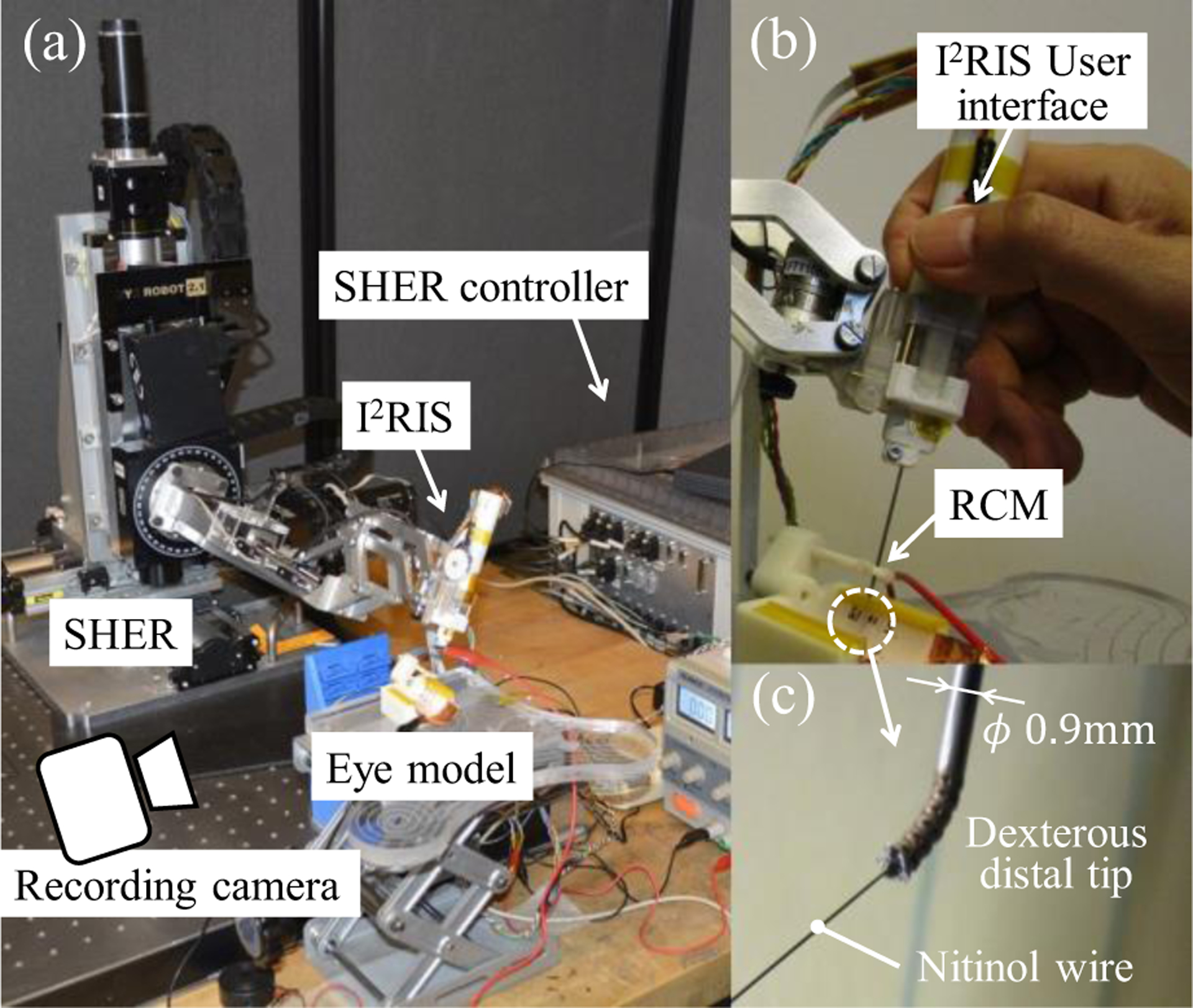
System overview of the integrated robotic assistant consisting of the new I2RIS with the user interface and SHER: (a) overview; (b) holding the I2RIS with the user interface visible; (c) dexterous distal unit. As a surgeon manipulates a tool position by holding the I2RIS, the dexterous distal tip can approach a target from various directions using the I2RIS user interface.
II. Robotic System Design
A. System Overview
The first iteration of the IRIS [19] was designed for handheld operation. However, it did not have a user interface and usability experiments were not performed. The second version was intended for use in combination with a SHER system [21]. The concept of the manipulation process was as follows: (1) cooperative control of the SHER for gross tool manipulation by the surgeon holding the IRIS; and (2) fine targeting by teleoperating the dexterous tip through a Phantom Omni. The IRIS bending motions of the pitch and yaw were controlled by the pitch and yaw manipulation enabled by the Phantom Omni. However, it was difficult to execute three-dimensional targeting and more complex tasks using this configuration, because the IRIS bending function, which was controlled by the Phantom Omni, was separated from the SHER control.
The proposed integrated robotic assistant, consisting of the new I2RIS with the user interface and SHER, is shown in Fig. 1. Fig. 2 displays the conceptual design of the dexterous distal unit of the IRIS, which is composed of 12 disk-like elements that provide two degrees of freedom (DOFs), with the bending joints (pitch and yaw axis) actuated by four wires. Fig. 3 illustrates the control scheme of the proposed integrated system, employing the I2RIS user interface. In this control scheme, the bending function of the I2RIS, which is controlled via the new tactile user interface, is integrated with the SHER control. Therefore, we can manipulate the dexterous distal tip of the snake in order to approach a target from various directions by holding the I2RIS alone. Additionally, with the integrated system it is possible to execute three-dimensional targeting tasks within the confined intraocular space of the human eye (see Fig. 3).
Figure 2.

Conceptual design of the dexterous distal unit of the IRIS: The unit is composed of 12 disk-like elements, providing 2-DOF bending joints actuated by four wires: (a) overview; (b) three-view drawing of an element (dimensions in mm) [19].
Figure 3.

Control scheme of the integrated system of the SHER and I2RIS with user interface.
B. Detachable Tool Unit Design
The I2RIS is designed with detachable units, such that the instrument unit (a snake-like surgical tool) can be detached from the motor unit for the purposes of cleaning, sterilization and the insertion of various types of surgical tools [22]. Moreover, in order to constructively integrate it with the SHER, it should be possible to detach the I2RIS from the SHER so as to allow interchangeability with various surgical tools. Fig. 4 displays a conceptual overview of the detachable I2RIS tool. The mechanical interface consists of two sets of guiding pins and holes, and two sets of latches, a handle lever and a spring. The I2RIS and other tools can be attached and detached from the SHER using the mechanical interface. As the I2RIS is attached and detached from above, the risk of collision with obstacles, such as a surgical patient’s anatomy, is reduced.
Figure 4.

Conceptual design of the detachable I2RIS: (a) mechnical interface of the SHER for the attachment of the I2RIS and various types of surgical tools prior to attachment; (b) I2RIS integrated with the SHER following attachment.
C. I2RIS User Interface Design
The I2RIS enables 2-DOF bending motions. Therefore, its user interface requires a 2-DOF-controllable unit. There are many kinds of 2-DOF control units, including trackballs, joysticks, mice, tactile switches, force sensors, tactile sensors, and so on. However, for the sake of implementation on the I2RIS, the user interface must be compact and user-friendly. It must also be controllable using only one finger (a thumb or index finger), while allowing the surgeon to manipulate the SHER with a single hand holding the I2RIS. Therefore, the user interface unit size should be close to that of human fingers, of less than 20mm×20mm×10mm. Fig. 5 shows two types of user interfaces designed on the basis of the aforementioned requirement, namely a tactile switch and an analog joystick.
Figure 5.

User interface design of the I2RIS: (a) installation of the user interface to the I2RIS and its coordinate system; (b) tactile switch unit; (c) joystick unit; motor velocity control methods of (d) the tactile switch; and (e) the joystick.
As is shown in Fig. 5 (b), the 2-DOF tactile switch control unit consists of four small tactile switches (dimensions: 6.2mm×6.2mm×3.1mm), a control pad and a base plate connected through a spherical joint at the center. Therefore, two adjacent tactile switches can be pushed simultaneously. The control pad has four protrusions and four depressions, whereby the user can understand the control directions by palpation without focusing on the user interface. In this way, it is possible to maintain control from eight directions by pushing each area of the control pad. As is shown in Fig. 5 (c), the 2-DOF joystick control unit consists of an analog joystick (JT8P-3.2T-B10K-1–16Y, Akizuki Denki Tsusho Co., Ltd.). The control knob can be slid in two normal directions and the unit has the capacity to return to a center position with springs. Similar to the tactile switch unit, the joystick unit can be controlled by a human operator using only the thumb while holding the I2RIS (see Fig. 1 (b)).
D. Control Method
Fig. 5 (d) and (e) show the motor velocity control methods for the I2RIS user interfaces. As is depicted in Fig. 5 (d), in the case of the tactile switch unit, the on/off motor velocity control commands generate a constant motor velocity. In the case of the joystick unit, shown in Fig. 5 (e), the analog motor velocity control commands generate variable motor velocities. Therefore, by releasing the thumb from the control pad or knob, the motors stop and hold the tool tip in a fixed position. The faster the maximum motor speed setting, the shorter the large-angle operating time; however, the resolution of the pointing angle will be coarser in this case. The maximum motor speed can be adjusted according to the procedure and the surgeon’s preference. In this paper, the maximum motor speeds for both interfaces are set to a resolution of about 4.5 degrees and a full-range (±45 degrees) bending motion time of about 3 seconds.
Without the bending motions, the I2RIS tip position is controlled by admittance control of the 5-DOF SHER using a six-axis force and torque sensor mounted on the distal end of the SHER [2, 14], as displayed in Fig. 4 (a). The remote center of motion (RCM) position (see Fig. 1 (b)), the contact point between the tool shaft and the eye model, is maintained by means of compensation control of the SHER. Therefore, the operator does not need to deal with the displacement of the sclerotomy point (Fig. 5 (a)) as a result of the I2RIS operation. In total, the operator can control the 5-DOF tool tip position with only one hand: a 3-DOF RCM motion can be performed by holding the I2RIS (attached to the SHER, with the cooperative control) and the 2-DOF bending motion is achieved by orientating the I2RIS dexterous distal tip, using the I2RIS user interface.
III. Experiments and Results
The goals of the experiments conducted for this study were to evaluate: (1) the dexterity of the integrated system; (2) the efficacy of the two user interfaces by means of pointing and insertion tasks.
A. Experimental Setup of the Pointing Tasks
The experimental setup is shown in Fig. 1 and consisted of the integrated robotic assistant, an eye model and a recording camera. Fig. 6 shows an overview and the detailed dimensions of the eye models utilized for the pointing tasks. The eye model consisted of a gimbal mechanism to mimic the sclerotomy point (also the SHER’s RCM point), a 3D-printed cylindrical ABS plastic plate with 5×3=15 holes (point numbers 1 to 15), a conductive copper plate and a buzzer. A nitinol wire, used as the needle indicator, was attached to the distal end of the I2RIS. The operator can monitor the wire tip motion with the naked eye and be alerted to the completion of each task (insertion of the nitinol wire tip into the holes) with the sound of the buzzer. The nitinol wire has a diameter of 0.125 mm and the hole has a diameter of 1 mm. This means that in this experiment, the pointing accuracy required for all tasks is less than ± 0.45 mm. Therefore, it is possible to evaluate the usability of the proposed interfaces by comparing task completion times.
Figure 6.

Overview and detailed dimensions of the eye model for the pointing tasks: (a) overview; (b) detailed dimensions of the eye model in the top and front view, and the point number. Dimensions are in mm.
B. Approaching Task from Varying Directions
The goal of this experiment was to evaluate the efficacy of the functional integration of the SHER and I2RIS in order to provide high surgical dexterity inside an eye. Specifically, we sought to prove that, by controlling the integrated system with one hand, the user is able to approach a target from different directions. In this preliminary experiment, the subject was a right-handed person with some experience in operating the SHER. The subject was required to control the robotic system and guide the nitinol wire tip to reach target point #8 (Fig. 5 (b)) from different directions. Fig. 7 shows the approaching task to the target. With the snake in a straight configuration, the subject inserted the tool tip inside the eye model by operating the SHER with a 5-DOF cooperatively-controlled motion. When the instrument tip reached the sclerotomy point, the virtual RCM control function of the SHER was activated. Moreover, the subject controlled the 2-DOF bending motion of the I2RIS dexterous distal tip using the user interface with one finger, while manipulating the SHER for the 3-DOF positioning motion using one hand. As can be seen in Fig. 7, using the integrated robotic system, the subject was able to easily approach the target from multiple directions using the I2RIS bending function. A conventional straight tool can approach the target from only one direction, which is determined by the sclerotomy point and the target’s position.
Figure 7.
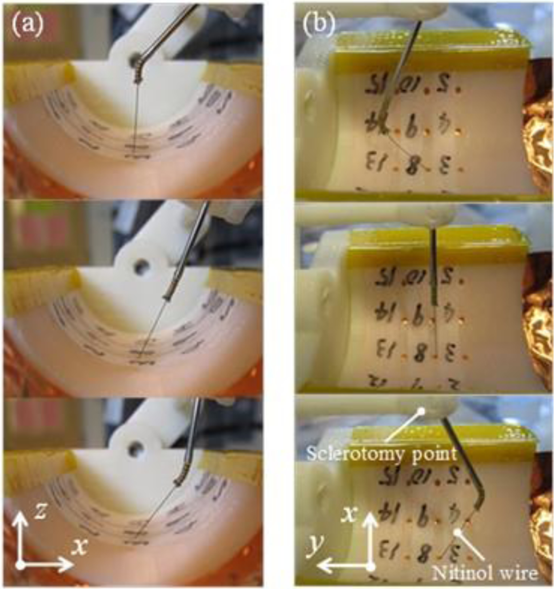
The task was to point to the number eight from varying directions using the bending function after passing through the sclerotomy point: (a) x-z plane view; (b) x-y plane view.
C. Pointing Task
The goal of this experiment was to compare the usability of the two proposed user interfaces described in Section II-C. A subject (right-handed, non-clinician) was asked to control the robotic system and guide the nitinol wire tip to reach all of the target points in a random order (but which were kept identical throughout the trials): the number 8 (home position, start point), then 10, 1, 7, 11, 8, 14, 15, 2, 2, 9, 6, 5, 13, 4, 3, and finally back to 8. The experimental conditions were as follows: (1) a straight I2RIS; (2) tactile switch; and (3) joystick. The straight I2RIS refers to manipulating the tool without using the bending function, which is therefore the same as manipulating a conventional straight tool. The subject operated the system by looking directly at the eye model. Before starting the experiment, the subject was required to familiarize him/herself with the integrated robotic assistant. The subject ran five trials for each condition, each of which was video-recorded, and the completion time was retrieved based on the video.
Fig. 8 shows the experimental results of the pointing task. As is shown in the figure, the task time for the straight I2RIS condition was slightly shorter than for the tactile switch and joystick. This was because the straight I2RIS manipulation was the simplest for the pointing task. The task time was shortened during the experiments because of the subject’s learning curve by repeating the trials. The trends for the straight I2RIS, tactile switch and joystick were also similar. These results indicate that by manipulating the I2RIS bending motion using the tactile switch or joystick, the task time increased by only 5.9% and 11.7%, respectively, compared to conventional straight tools.
Figure 8.

Pointing task time: (a) total time of the pointing task; (b) average time of each pointing task.
Fig. 9 displays the SHER tip position trajectory and orientation. This tip position is defined as is shown in Fig. 9 (g). In the case of the pointing task by the tactile switch and joystick, the SHER tip’s motion and orientation areas were smaller than those of the straight I2RIS. This is because the wire tip motion was defined by both systems, the I2RIS and SHER, and the user could manipulate the latter less in reaching for the same targets compared to the straight tool.
Figure 9.
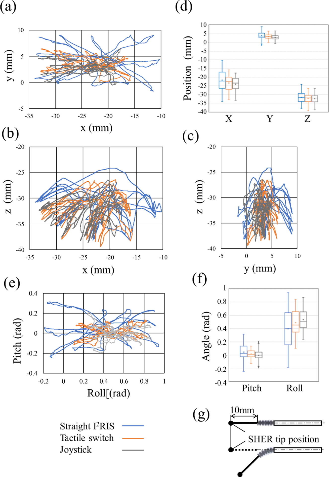
SHER tip position trajectory and orientation of the pointing task: (a) x-y plane; (b) x-z plane; (c) y-z plane; (d) box plot of displacement distribution; (e) orientation; (f) box plot of orientation distribution; (g) definition of the SHER tip position. The motion areas of the tactile switch and joystick were smaller than the straight I2RIS.
D. Preliminary Evaluation of the Pointing Task
The goal of this preliminary study was to compare the usability of the I2RIS user interfaces. Two subjects (right-handed, non-clinician, expert SHER users, and different from the user in Section III-C) were required to control the robotic system and guide the nitinol wire tip to reach five target points in a random order: starting with the number 8 (the home position and starting point), followed by 1, 4, 11, 14 and back to 8. Apart from the starting and ending points, the order of the other target points was randomly defined and differed in each trial. The experiment used the tactile switch and the joystick. Prior to the start of the experiment, the subjects were required to familiarize themselves with the integrated robotic assistant for five minutes. Each subject ran ten trials for each condition (with random starting conditions amongst the subjects), each trial was video-recorded and the completion time retrieved on the basis of the video.
Fig. 10 shows the experimental results. For both subjects, the joystick task times were shorter than the tactile switch ones, regardless of the experimental order. Considering all of the completion times (Fig. 8 and Fig. 10), in the case of pointing task, it can be concluded that there were differences between subjects based on their preferences or skills, but both user interfaces featured enough usability to deftly control the integrated robotic assistant.
Figure 10.
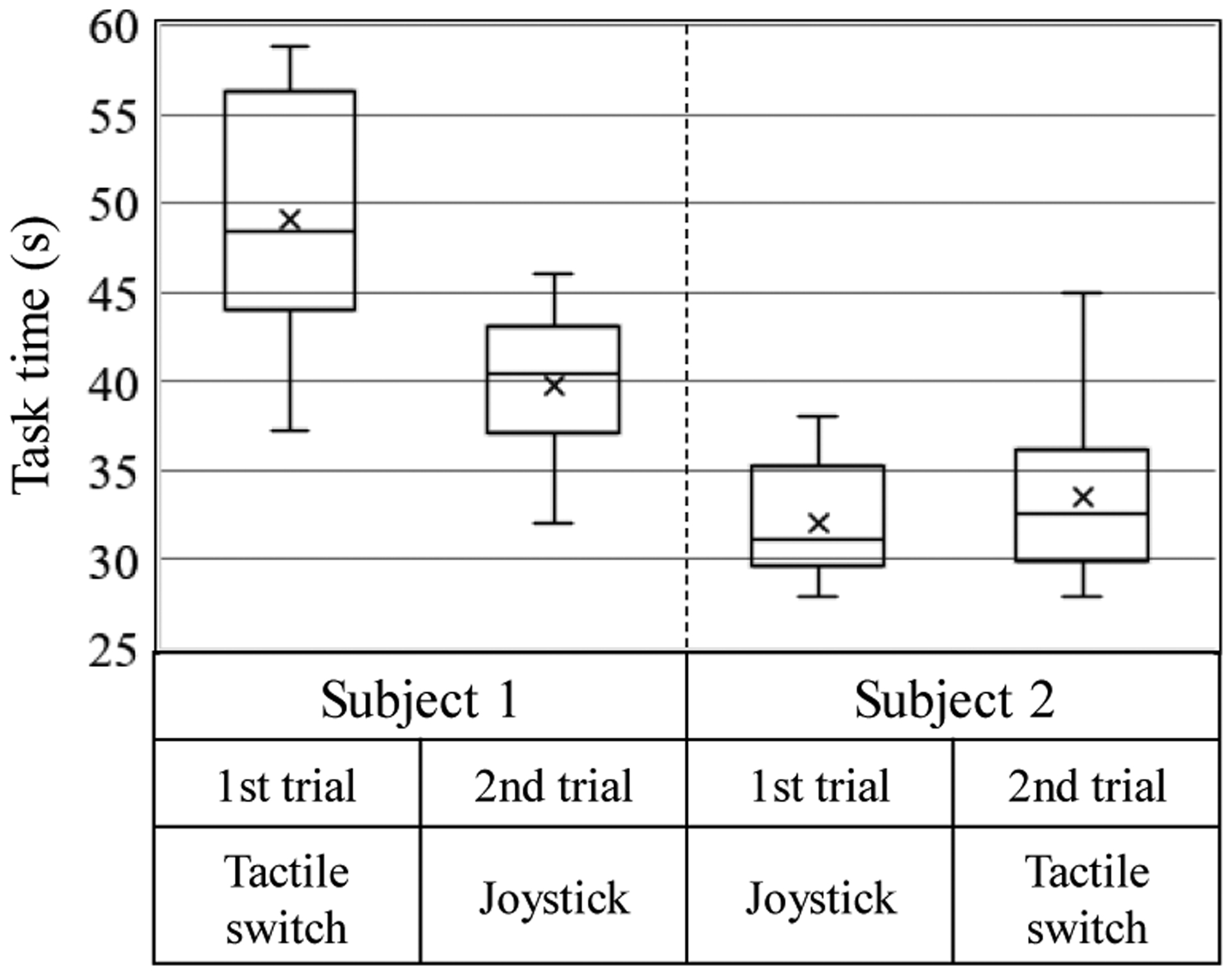
Box plot of the pointing task experiments; the task times were four random points and the home position pointing time, with data from ten trials.
E. Insertion Task
The goal of the insertion task was to mimic the performance of a retinal vein cannulation procedure from various directions using the integrated robotic assistant. An eye model with diagonally-placed holes was designed to mimic retinal veins. Fig. 11 shows the overview and detailed dimensions of the eye model for the insertion tasks. The eye model consisted of a spherical surface plastic plate with four diagonally-located holes, whose diameter was 0.8 mm on the RCM point side. The operator’s task was to control the dexterous distal tip direction of the nitinol wire aligning to the diagonal hole direction with the user interface and to insert the nitinol wire deeply enough to touch the conductive copper plate.
Figure 11.
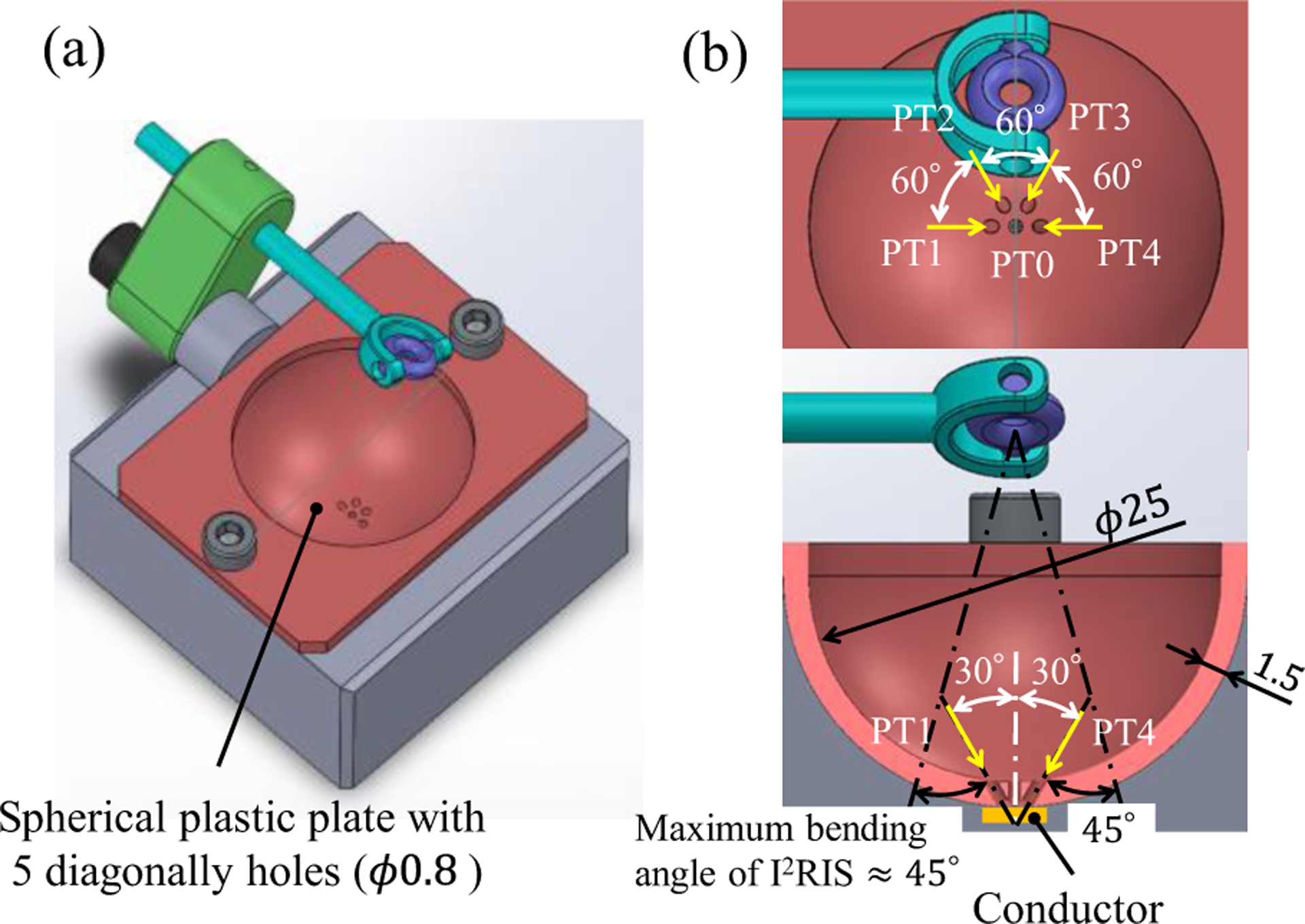
Overview and detailed dimensions of the eye model for the insertion tasks: (a) overview; (b) detailed dimensions of the eye model from top and front views and the point number. (Dimensions are in mm).
One subject, who performed the experiment in Section III-D, was asked to control the robotic system to guide and insert the nitinol wire tip into four diagonal holes in a random order. Fig. 12 shows the experimental results of the ten trials, each of which was video-recorded, with the completion time determined on the basis of the video.
Figure 12.
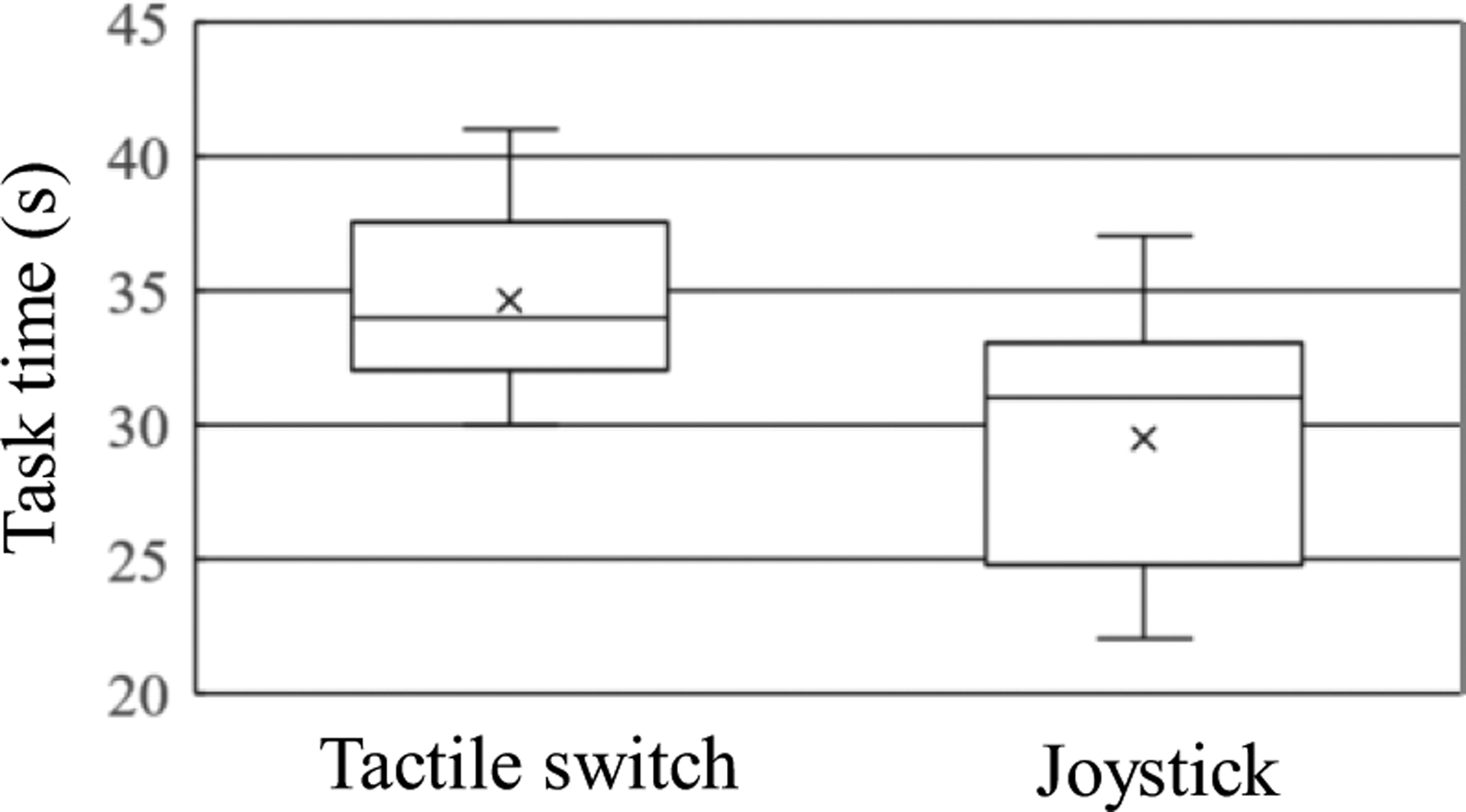
Box plot of the insertion task experiments by Subject 1; the task times were four random point insertion times. Data from 10 trials.
The subject was able to easily carry out the insertion tasks using the user interfaces, with similar facility to the pointing tasks. Moreover, the joystick task times were shorter than the tactile switch ones. In the case of the insertion task, we could also conclude that both user interfaces provided sufficient usability for effectively controlling the integrated robotic assistant.
IV. Discussion and Conclusions
In this study we developed an integrated, high-dexterity, cooperative robotic assistant for intraocular micro-manipulation tasks. The results of this study were as follows: (1) two user interfaces, using a joystick and tactile switch and related control systems for I2RIS, were developed; (2) the I2RIS was integrated with the SHER device; (3) the efficiency of the integrated system in providing high-dexterity manipulation in confined spaces was verified through pointing and insertion tasks experiments.
It is noteworthy that the strategy employed by both subjects (who had extensive experience in controlling SHERs) in guiding the wire tip inside the eye (Section III-D) was the same: (1) the wire’s gross positioning was performed with the SHER (by hand); (2) the snake direction was modified or aligned using the I2RIS user interface (by finger); (3) the target point was reached or insertion of the tip performed using the SHER (by hand). Each subject controlled one system at a time and, for the final tip positioning step, they used the highly accurate (micron-scale) motion offered by the SHER. While this strategy proved to be efficient, it could be improved upon by coordinating the hand and finger motions and potentially by combining the first two steps listed above. However, combining the local movements of the snake with the macro movements of the instrument presents a highly unique challenge and further experiments are necessary to optimize this approach.
Based on the experimental results, we can conclude that:
The user was able to control the 2-DOF orientation of the dexterous distal tip using the I2RIS user interface with one finger while manipulating its 3-DOF position with one hand, using the SHER to easily carry out the pointing and insertion tasks.
Unlike conventional straight tools, with the I2RIS, the user can touch or insert the tip into the same target from different directions by controlling the bending function with the I2RIS user interfaces. There was no significant increase in the task completion time for either user interface.
When controlling the integrated system to perform the pointing tasks, the user was required to manipulate comparatively less of the SHER than in the case of conventional straight tool manipulation.
There are differences between users depending on their personal preferences or skills acquired through training, but both interfaces feature enough usability to effectively control the integrated robotic assistant.
Future work will focus on: (1) extending the multi-user experiments for further investigation of the tactile switch and joystick; (2) designing and implementing the end-effectors (such as the needle, grasper, optical fiber and energy device) for the I2RIS and related user interfaces; (3) functional integration of the I2RIS with the end-effectors and the SHER system; and (4) usability evaluations of the system as a whole including more quantitative data about precision and surgeon fatigue.
Supplementary Material
Acknowledgments
Research supported in part by the off-campus researcher dispatch program of Kokushikan University, by U.S. National Institutes of Health under grant number 1R01EB023943-01, and by Johns Hopkins University internal funds.
References
- [1].Vander Poorten E, Riviere CN, Abbott JJ, Bergeles C, Nasseri MA, Kang JU, Sznitman R, Faridpooya K, and Iordachita I, 36 - Robotic Retinal Surgery, Handbook of Robotic and Image-Guided Surgery, Elsevier, 2019, pp. 627–672. [Google Scholar]
- [2].Fleming I, Balicki M, Koo J, Iordachita I, Mitchell B, Handa J, Hager G, Taylor R, “Cooperative robot assistant for retinal microsurgery,” Med. Image Comput. Comput. Assist. Interv, vol. 5242, 2008, pp.543–550. [DOI] [PubMed] [Google Scholar]
- [3].Gijbels A, Wouters N, Stalmans P, Van Brussel H, Reynaerts D, Vander Poorten E, “Design and realisation of a novel robotic manipulator for retinal surgery,” Proc. IEEE Int. Conf. on Intelligent Robots and Systems, Tokyo, 2013, pp.3598–3603. [Google Scholar]
- [4].Tanaka S, et al. “Quantitative assessment of manual and robotic microcannulation for eye surgery using new eye model,” Int J Med Robotics Comput Assist Surg, April. 2014. [DOI] [PubMed] [Google Scholar]
- [5].Wei W, Popplewell C, Chang S, Fine HF, Simaan N, “Enabling technology for microvascular stenting in ophthalmic surgery,” Journal of Medical Devices, vol. 4, no. 1, March. 2010. [Google Scholar]
- [6].Jensen PS, Grace KW, Attariwala R, Colgate JE, Glucksberg MR, “Toward robot-assisted vascular in the retina,” Graefe’s Arch Clin Exp Ophthalmol. Vol. 235, no. 11, pp.696–701. November. 1997. [DOI] [PubMed] [Google Scholar]
- [7].Latt WT, Tan UX, Shee CY, Ang WT, “A compact handheld active physiological tremor compensation instrument,” Proc. lEEE/Amer. Soc. Mech. Eng. Int. Conf. Adv. Intell. Mechatronics, 2009, pp.711–716. [Google Scholar]
- [8].Becker BC, Yang S, MacLachlan RA, Riviere CN, “Towards vision-based control of a handheld micromanipulator for retinal cannulation in an eyeball phantom,” Proc. 4th IEEE RAS EMBS Int. Conf. Biomed. Robot. Biomechatron, 2012, pp.44–49. [DOI] [PMC free article] [PubMed] [Google Scholar]
- [9].Payne CJ, Kwok K, Yang G, “An ungrounded hand-held surgical device incorporating active constraints with force-feedback,” Proc. IEEE Int. Conf. on Intelligent Robots and Systems (IROS ‘13), 2013, PP.2559–2565. [DOI] [PMC free article] [PubMed] [Google Scholar]
- [10].Chang D, Gu GM, Kim J, “Design of a novel tremor suppression device using a linear delta manipulator for micromanipulation,” Proc. IEEE Int. Conf. on Intelligent Robots and Systems (IROS ‘13), 2013, pp.413–418. [Google Scholar]
- [11].Kummer MP, Member SS, Abbott JJ, Kratochvil BE, Borer R, Sengul A, Nelson BJ, “OctoMag: An Electromagnetic System for 5-DOF Wireless Micromanipulation”, IEEE Transactions on Robotics. Vol. 26, no. 6, pp.1006–1017, 2010. [Google Scholar]
- [12].Charreyron Samuel L., Gabbi Edoardo, Boehler Quentin, Becker Matthias, and Nelson Bradley J.. “A magnetically steered endolaser probe for automated panretinal photocoagulation.” IEEE Robotics and Automation Letters 4, no. 2 (2018): xvii–xxiii. [Google Scholar]
- [13].Lin Fang-Yu, Bergeles Christos, and Yang Guang-Zhong. “Biometry-based concentric tubes robot for vitreoretinal surgery.” 2015 37th annual international conference of the IEEE engineering in medicine and biology society (EMBC). IEEE, 2015. [DOI] [PubMed] [Google Scholar]
- [14].Üneri Ali, Balicki Marcin A., Handa James, Gehlbach Peter, Taylor Russell H., and Iordachita Iulian. “New steady-hand eye robot with micro-force sensing for vitreoretinal surgery.” In 2010 3rd IEEE RAS & EMBS International Conference on Biomedical Robotics and Biomechatronics, pp. 814–819. IEEE, 2010. [DOI] [PMC free article] [PubMed] [Google Scholar]
- [15].Ding J, Xu K, Goldman R, Allen P, Fowler D, Simaan N, “Design simulation and evaluation of kinematic alternatives for insertable robotic effectors platforms in single port access surgery”, IEEE International Conference on Robotics and Automation, 2010. pp. 1053–1058. [Google Scholar]
- [16].Kutzer MD, Segreti SM, Brown CY, Armand M, Taylor RH, Mears SC, “Design of a new cable-driven manipulator with a large open lumen: Preliminary applications in the minimally-invasive removal of osteolysis,” IEEE International Conference on Robotics and Automation, 2011, pp. 2913–2920. [Google Scholar]
- [17].Roppenecker DB, Pfaff A, Coy JA, Lueth TC, “Multi arm snake-like robot kinematics,” IEEE/RSJ International Conference on Intelligent Robots and Systems, 2013, pp. 5040–5045. [Google Scholar]
- [18].Qi P, Qiu C, Liu H, Dai JS, Seneviratne L, Althoefer K, “A novel continuum-style robot with multilayer compliant modules,” IEEE/RSJ International Conference on Intelligent Robots and System, 2014, pp.3175–3180. [Google Scholar]
- [19].He X, Geirt VV, Taylor R, lordachita I, “IRIS: Integrated robotic intraocular snake,” IEEE International Conference on robotics and automation, 2015, pp.1764–1769. [DOI] [PMC free article] [PubMed] [Google Scholar]
- [20].Kim Y-J, Cheng S, Kim S, and Iagnemma K, “A stiffness-adjustable hyperredundant manipulator using a variable neutral-line mechanism for minimally invasive surgery,” IEEE Transactions on Robotics, vol. 30, no. 2, pp. 382–395, 2014. [Google Scholar]
- [21].Song J, Gonenc C, Guo J, Iordachita I, “Intraocular Snake Integrated with the Steady-Hand Eye Robot for Assisted Retinal Microsurgery,” IEEE International Conference on robotics and automation, 2017, pp.6724–6729. [DOI] [PMC free article] [PubMed] [Google Scholar]
- [22].Jinno M and Iordachita I, “Improved Integrated Robotic Intraocular Snake,” 2020 International Symposium on Medical Robotics (ISMR), 2020. [DOI] [PMC free article] [PubMed] [Google Scholar]
Associated Data
This section collects any data citations, data availability statements, or supplementary materials included in this article.