

Abstract
Periodontitis is a chronic inflammatory, bacteria-triggered disorder affecting nearly half of American adults. Although some level of tissue regeneration is realized, its low success in complex cases demands superior strategies to amplify regenerative capacity. Herein, highly ordered scaffolds are engineered via Melt ElectroWriting (MEW), and the effects of strand spacing, as well as the presence of a nanostructured fluorinated calcium phosphate (F/CaP) coating on the adhesion/proliferation, and osteogenic differentiation of human-derived periodontal ligament stem cells, are investigated. Upon initial cell-scaffold interaction screening aimed at defining the most suitable design, MEW poly(𝝐-caprolactone) scaffolds with 500 µm strand spacing are chosen. Following an alkali treatment, scaffolds are immersed in a pre-established solution to allow for coating formation. The presence of a nanostructured F/CaP coating leads to a marked upregulation of osteogenic genes and attenuated bacterial growth. In vivo findings confirm that the F/CaP-coated scaffolds are biocompatible and lead to periodontal regeneration when implanted in a rat mandibular periodontal fenestration defect model. In aggregate, it is considered that this work can contribute to the development of personalized scaffolds capable of enabling tissue-specific differentiation of progenitor cells, and thus guide simultaneous and coordinated regeneration of soft and hard periodontal tissues, while providing antimicrobial protection.
Keywords: 3D printing, bones, melt electrowriting, periodontal regeneration, periodontitis, scaffolds
1. Introduction
Periodontitis (gum disease) is a ubiquitous chronic inflammatory, bacteria-triggered disorder affecting nearly 50% of American adults.[1] If left untreated, it leads to severe destruction of the periodontium (i.e., cementum, periodontal ligament (PDL), and alveolar bone), eventually resulting in tooth loss.[1,2] Over the years, countless therapies have been investigated for regenerating tooth-supporting tissues lost as a consequence of periodontal disease progression. Hitherto, the management of periodontal tissue destruction encompassed scaling and root planning, flap surgery, and guided tissue regeneration by means of a degradable membrane that, while serving as a barrier against soft tissue infiltration, allows resident progenitor cells to promote the regeneration of periodontal tissues.[2] Although some level of tissue regeneration has been realized, the low success in complex cases (e.g., horizontal defects) demands superior strategies to strengthen regenerative capacity, regardless of damage severity.
Recent advances associated with the development of scaffolds that provide desirable functionalities, including anti-inflammatory, antimicrobial, and regenerative attributes by means of the incorporation of drugs and/or biologics, as well as engineering tools to devise defect-specific scaffolds, have been witnessed.[3–5] Significant progress has been made that leverages the electrospinning (solution-based) nanotechnology for the fabrication of versatile biodegradable scaffolds with 3D nanofibrous microstructure resembling the extracellular matrix (ECM) of native tissues.[6] However, this method fails to generate scaffolds with patient-specific geometries that address the 3D architectural complexity of periodontal defects. Moreover, the rather flat, densely packed fibrous structure of electrospun scaffolds often limit cellular infiltration.[7] Collectively, the lack of controlled fiber deposition and space between adjacent layers has ignited the search for technologies capable of not only mimicking the microstructural features of native ECM, but also creating geometrically defined scaffolds for periodontal tissue reconstruction.
Additive manufacturing (AM) technologies, such as fused deposition modeling (FDM) and selective laser sintering (SLS), have paved the way for fabrication of defect-specific scaffolds.[8] Although AM has been deployed to engineer personalized biomaterials for regenerative medicine applications (e.g., tracheal splints), data from a seminal clinical study in periodontics demonstrated that, even though a patient-specific scaffold in poly(𝜖-caprolactone) (PCL) could be made, its overall ability to fabricate constructs with a degradation rate matching that of periodontal tissues’ regeneration remains intangible, particularly due to the generally bulky nature of the printed scaffold.[8] To address this technology gap, Melt ElectroWriting (MEW) holds significant potential, since it allows for the generation of microscale fibers and controlled fiber deposition to ultimately create more physiologically relevant 3D scaffolds for periodontal tissue regeneration. Worth mentioning, MEW not only enables the fabrication of scaffolds with cell-invasive ability, but also macro- and microstructural features, such as scaffold porosity, as well as fiber diameter and alignment to match tissue-specific requirements, respectively. Worth noting, post-processing modifications are accessible through coating strategies aiming at regulating cell differentiation and tissue formation. In this way, in view of the hydrophobic character of PCL and its poor cellular attachment ability, surface modification using plasma, alkali-treatment, or calcium phosphate (CaP) coatings has been investigated.[9] Remarkably, fluorapatite (FA), a bioceramic within the CaP family, has been shown to favorably influence osteogenic differentiation while also displaying antimicrobial action, which, in the case of periodontal regeneration, would be important for preventing bacterial colonization.[10] Moreover, Sikder et al. reported on the bioactivity of fluoro-hydroxyapatite coating and its potential to form bone-like apatite globules.[2,11]
In this work, PCL scaffolds were fabricated via MEW, the effects of strand spacing, and the presence of a fluorinated CaP (F/CaP) coating on the attachment; proliferation and osteogenic differentiation of human-derived periodontal ligament stem cells (hPDLSCs) were investigated to refine the most favorable candidate for use as bone region in a zonal, tissue-specific scaffold for periodontal tissue regeneration. MEW was utilized to print box-structured scaffolds by alternating the layer deposition via 0°/90° layers to obtain three distinct strand spacings (up to 1000 µm). Upon initial screening of cell-scaffold interaction to define the most suitable scaffold design, 500 µm strand spacing was chosen. Following an alkali treatment, the aforesaid scaffolds were immersed in a pre-established solution to allow for coating formation. A nanostructured F/CaP coating was observed on the MEW-printed PCL fibers through high-resolution imaging. The presence of the nanostructured F/CaP coating led to a significant increase in cell proliferation and marked upregulation of osteogenic genes. Moreover, the antimicrobial character of the F/CaP-coated scaffolds was examined. Our data indicated a minor, yet significant action against P. gingivalis. In vivo findings demonstrated that the F/CaP-coated scaffolds are biocompatible and lead to periodontal tissue regeneration when implanted in a well-established fenestration defect model in rodents.
2. Results and Discussion
2.1. Fabrication and Characterization of MEW PCL Scaffolds
MEW was utilized to engineer highly ordered polymeric (PCL) scaffolds for periodontal regeneration (Figure 1a). The scaffolds showed uniform 3D architecture in all designed strand spacings, with well-aligned fibers having an average fiber diameter of 2.3 ± 0.1 µm and an overall porosity (%) of 91.7, 93.9, and 94.4 in 500, 750, and 1000 µm strand spacing, respectively. It is well-known that PCL has low surface hydrophilicity, which limits cell adhesion.[12] In order to improve the wettability of the generated fibers and enhance cellular attachment, the scaffolds were etched with sodium hydroxide (NaOH).[13]
Figure 1.
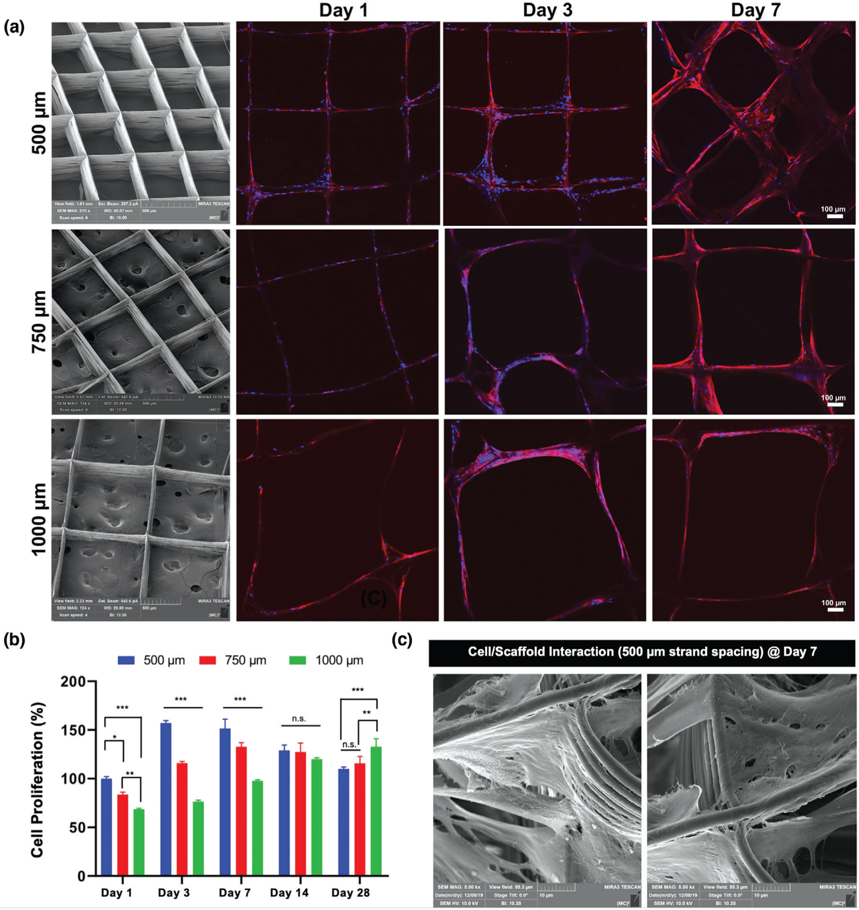
Effects of strand spacing on the attachment and proliferation of hPDLSCs. a) Representative SEM images of the various MEW PCL scaffolds show well-aligned and defect-free fiber morphology, and distinct strand spacings (500, 750, and 1000 µm) at 0–90°-oriented junctions. Confocal microscopy images of hPDLSCs seeded on the scaffolds after 1, 3, and 7 days of culture. Of note, hPDLSCs show more prominent attachment and proliferation on PCL scaffolds with a 500 µm strand spacing. DAPI (blue) and phalloidin (red) fluorescent staining (scale bar = 100 µm). b) hPDLSCs’ proliferation on MEW scaffolds measured using alamarBlue assay over 28 days of culture. Mean ± SD (n = 3). ANOVA: ***p < 0.001, **p < 0.01, *p < 0.05. c) SEM images of hPDLSCs on MEW PCL scaffold at 7 days.
Scaffold strand spacing (pore size) and pore interconnectivity have been acknowledged as two of the most prominent design parameters dictating cellular response and function.[14,15] In order to assess the effect of the varying scaffold strand spacings on cell attachment and proliferation, hPDLSCs were seeded, and then observed with confocal laser scanning microscopy (CLSM). Improved cell attachment and proliferation on scaffolds having 500 µm strand spacing was noted when compared to the larger (750 and 1000 µm) strand spacing designs (Figure 1a). It was observed that scaffolds with a strand spacing of 500 µm exhibited superior cell bridging after 3 days than scaffolds with larger strand spacings. These findings confirm that strand spacing plays a role in cell attachment and proliferation.[15] For quantitative purposes, we evaluated whether increased strand spacing could affect cell viability using the alamarBlue assay (Figure 1b). Cell proliferation was statistically higher in 500 µm strand spacing scaffolds when compared to the other groups. At days 1 through 7, the effects of strand spacing were evident between 500 and 750 µm, while between days 7 and 28, a marked increase in viability was noted in strand spacings of 1000 µm. Particularly, on day 1 through 7 the viability of hPDLSCs on 500 µm strand spacing scaffolds was significantly greater than those in 750 and 1000 µm. Collectively, cells in small strand spacings (500 µm) had a higher contact rate, which allowed for faster spreading across strands. From a biological viewpoint, producing scaffolds with varying strand spacings from 100 to 750 µm allows for suitable cellular attachment and growth.[15,16] Importantly, while larger strand spacing impacts cell survival, smaller spacing better supports cell viability and proliferation.[15–18]
Our findings agree with previous studies, where cell proliferation was greatly influenced by pore size.[15,19] Noteworthy, at day 14, proliferation decreased in the 500 and 750 µm groups, possibly due to growth impairment due to cell–cell contact. In agreement with previous research, small strand spacings restricted cell infiltration and subsequently created more interactions between cells to promote differentiation (Figure 1c), while cells in larger strand spacings were able to continue proliferating.[15,20] Altogether, due to halted proliferation in larger strand spacings at early timepoints and handling difficulties when using scaffolds with 750 and 1000 µm strand spacings, we focused on evaluating the potential of our innovative F/CaP coating solely on scaffolds with 500 µm strand spacing.
Apatite formation on inert polymers (e.g., PCL) does not occur spontaneously, and specific surface modifications are needed to activate its surfaces.[13,21–25] Representative scanning electron microscope (SEM) images of the NaOH-etched and the F/CaP-coated scaffolds are shown in Figure 2. The fiber morphology of F/CaP-coated scaffolds revealed a unique nanostructured surface depicted as irregular-shaped nanoparticles (≈50–150 nm) and a homogenous rough layer covering each individual fiber. Representative atomic force microscopy (AFM) images of the scaffolds showed statistically significant differences in roughness. The PCL fibers of the coated scaffolds displayed the greatest mean roughness average (Ra) values, followed by the etched and pristine fibers (Figure 2).
Figure 2.
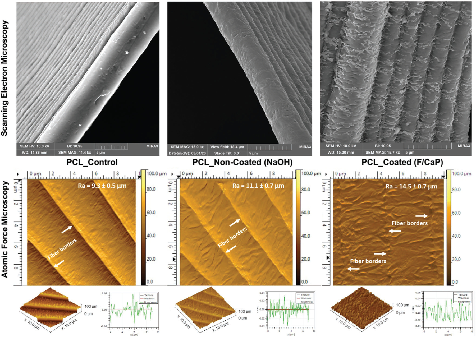
Representative SEM (top) and AFM (bottom) images of the MEW scaffolds show distinct surface texture: control (nonetched), NaOH-etched, and F/CaP-coated scaffolds. Please note that due to the increased roughness pattern associated with the F/CaP-coated fibers the 3D plot of the surface texture does not obviously display the step-like characteristic evidenced in the other two groups.
Next, we determined the chemical nature of the F/CaP coating through Fourier-transform infrared spectroscopy (FTIR) and X-ray diffraction (XRD). The FTIR spectra of the pristine (control) scaffolds showed characteristic PCL peaks at 2946, 2865, and 1720 cm−1, corresponding to CH2 and C═O stretching, respectively.[26,27] Meanwhile, apatite peaks were identified in the spectra of coated scaffolds (Figure 3a). A broad peak stretching related to the phosphate group was identified between ≈565 and 960 cm−1. Further, the broad band in the range ≈3000–3750 cm−1 (O–H stretching) and the band identified at 1600 cm−1 suggests carbonated apatite formation.[28] The O–H stretching band at ≈740 cm−1 indicates the presence of hydroxyl that bonded to fluorine (F–OH); however, the exact amount of fluorine cannot be determined.[29,30] The XRD pattern of the pristine PCL scaffolds displayed two sharp peaks at 21.4° and 23.8°, respectively (Figure 3b); whereas, the coated scaffolds had a pattern similar to the noncoated scaffolds in addition to a discrete peak at ≈31.8°, likely due to the CaP phase presence.
Figure 3.
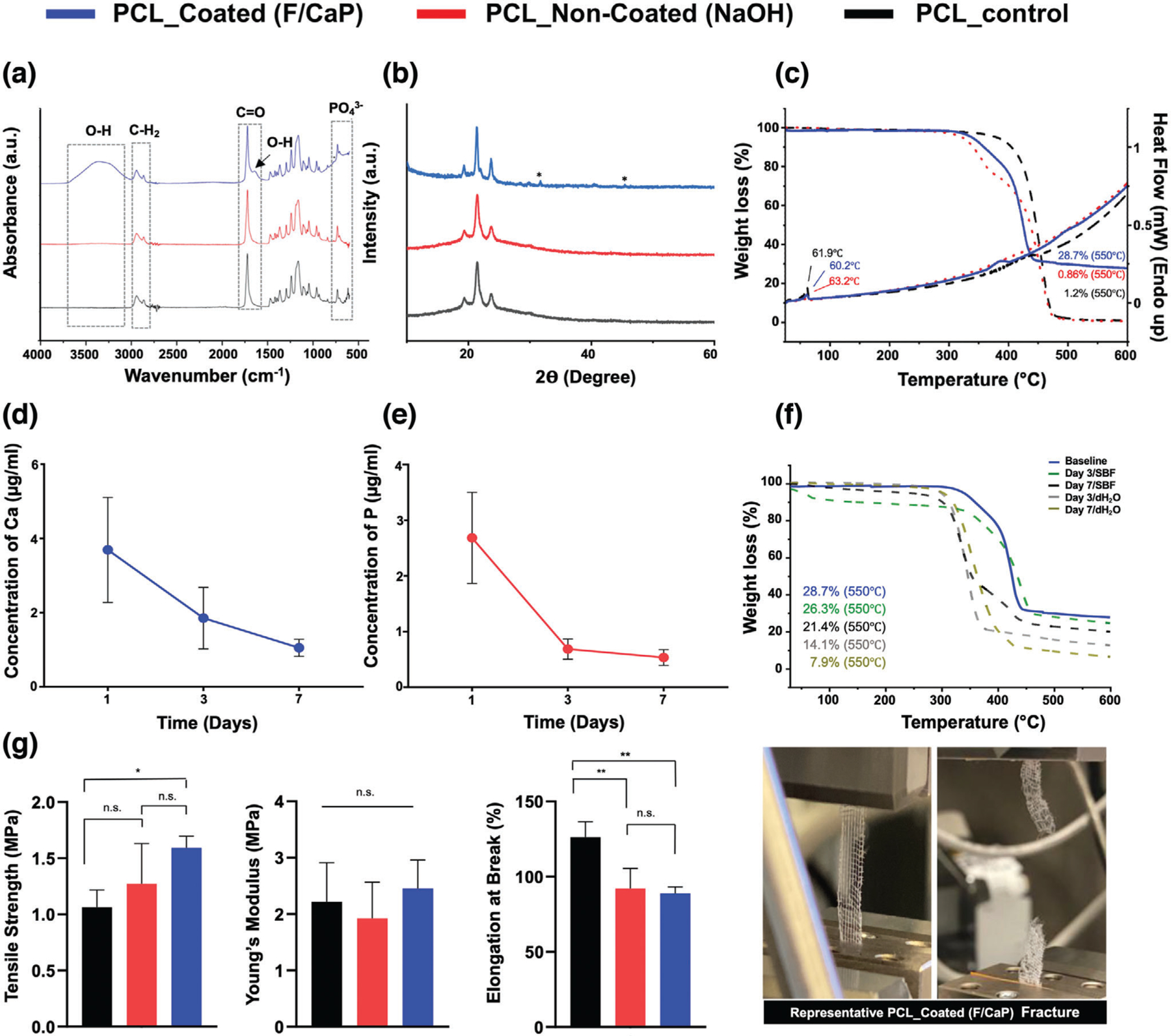
Chemical and mechanical analyses of pristine, NaOH-etched, and F/CaP-coated scaffolds. a) FTIR data show the chemical functional groups related to phosphate ≈565 and ≈960 cm−1 in F/CaP-coated scaffolds, confirming successful chemical modification. (*) indicates the presence of OH-F trace. b) XRD data show peaks similar to pristine PCL and weak peaks appearing at ≈25.9° and 31.8°; these weak peaks can be attributed to the presence of weak crystalline structure. c) The TGA-DSC curves of pristine (nonetched), NaOH-etched, and F/CaP-coated scaffolds. d,e) Ions’ release from F/CaP-coated scaffolds were measured in supernatants by means of ICP-MS, d) Ca ion concentration and e) P ion concentration in 10 mL dH2O for time periods ranging from day 1 to 7. f) Residual mass of the mineral phase after weight loss measured using TGA, after incubation in dH2O and SBF for time periods ranging from day 3 to 7. g) Uniaxial tensile testing setup showing an MEW PCL scaffold (500 µm strand spacing) prior to and after testing. Tensile strength, in MPa; Young’s modulus, in MPa; and elongation at break, in %. Overall, F/CaP-coated scaffolds show enhanced tensile strength and Young’s modulus compared to their noncoated and pristine counterparts. Mean ± SD (n = 4). ANOVA: ***p < 0.001, **p < 0.01, *p < 0.05.
The thermal stability of F/CaP-coated scaffolds in comparison to noncoated (NaOH-etched) and pristine (control) is shown in Figure 3c. All scaffolds displayed a single-step stable thermal degradation profile with initial weight loss due to residual moisture removal, followed by degradation at 370, 320, and 350 °C for pristine, noncoated, and coated scaffolds mainly attributed to large-scale thermal degradation of PCL. In addition, the residual weight of coated scaffolds at 550 °C was 28.7%, thus confirming the successful chemical (F/CaP) modification. The differential scanning calorimetry (DSC) curves showed prominent endothermic peaks of PCL at 61.9, 60.2, and 63.2 °C in pristine, NaOH-etched, and F/CaP-coated scaffolds, respectively, attributed to the melting temperature (Tm) of PCL, followed by a maximum decomposition rate, which was observed at ≈630 °C in F/CaP-coated scaffolds.
To determine the chemical stability of coatings in vitro, the simplest physiological approaches include sample incubation in distilled water or deionized water. The inductively coupled plasma mass spectrometry (ICP-MS) data demonstrate constant Ca and P ions’ release from the F/CaP-coated scaffolds over 7 days (Figure 3d,e). At day 1, the concentrations of Ca and P reached a higher value of 3.96 and 2.35 µg Ml−1, respectively. While at day 3 and day 7, the concentration of ions shows constant release values of 1.85–1.05 and 0.69–0.54 µg mL−1 for Ca and P, respectively. Despite the fact that the release data show continuous liberation up to 7 days of ions into water, the absence of buffer capacity does not appropriately mimic the in vivo scenario.[31] To simulate the in vivo environment, the chemical stability of F/CaP-coated scaffolds was also assessed after soaking the scaffolds in simulated body fluid (SBF). It can be seen from Figure 3f that after 1 week of SBF immersion, the residual mass for F/CaP-coated scaffolds was 26.3% and 21.4% for day 3 and 7, respectively. Meanwhile, when coated scaffolds were soaked in distilled water, the remaining mass was reduced nearly to half (14.1%) of the baseline data after 3 days, and to 7.9% at day 7. Collectively, the ICP-MS data and mineral phase stability (thermal gravimetric analysis (TGA)) findings support the positive in vivo findings of abundant bone regeneration. Similarly, highly purified 𝛽-TCP in many clinical settings showed high potential to be readily absorbed and replaced by newly formed bone compared to hydroxyapatite (HA), which is more resistant to biodegradation.[32,33]
The biomechanical properties of the scaffolds (i.e., F/CaP-coated, noncoated (NaOH-etched), and pristine PCL with 500 µm strand spacing) were determined using a uniaxial tensile test (Figure 3g). Regardless of the coating presence, the scaffolds showed a similar fracture behavior typical of most polymeric scaffolds—an initial elastic response, then considerable plastic deformation till failure.[34] The tensile strength and Young’s modulus were enhanced in the coated scaffolds when compared to the noncoated and significantly increased compared to pristine PCL. The data show clear enhancement of the mechanical properties as a result of uniform coating in the scaffolds. It is well-established that as the strength and rigidity of a scaffold increases, the elongation at break (%) decreases.[21] This behavior is obvious when comparing noncoated (≈98%), pristine (≈126.2) to F/CaP-coated scaffolds (≈84%).
2.2. In Vitro Bioactivity of F/CaP-Coated MEW PCL Scaffolds
The bone-forming potential of a biomaterial can be determined by evaluating the ability to form apatite on its surface in vitro,[22] following immersion in SBF.[23] SEM images (Figure 4a) show that, when F/CaP-coated scaffolds were immersed in SBF, reprecipitation of the apatite layer occurred, and it was followed by changes in the surface topography of the fibers and the formation of spherical cauliflower-like apatite morphologies. This is due to the ion exchange between the scaffold surface and SBF.[24] Meanwhile, the surface of NaOH-etched scaffolds revealed globules of mineral precipitates similar to previous observations for alkali-treated PCL upon SBF immersion.[35] Despite the trace of CaP precipitation detected in NaOH-etched scaffolds, visually, the coated scaffolds exhibited more apatite-like structures. The precipitates seen on the surface of the coated scaffolds continued to grow to form fully covered surfaces from day 7 to day 14 (Figure 4a). Moreover, the energy-dispersive X-ray spectroscopy (EDS) results (Figure 4b) showed that, as the immersion period increased, the calcium concentrations on the coated scaffolds also increased, thus reaching a ratio similar to that seen in natural bone.[36] This noticeable apatite-like phase formation on the coated scaffold likely occurred due to CaP deposition onto the scaffold’s surface, which acted as a precursor of apatite and spontaneously allowed apatite growth by consuming Ca and P ions from the SBF solution.[22]
Figure 4.
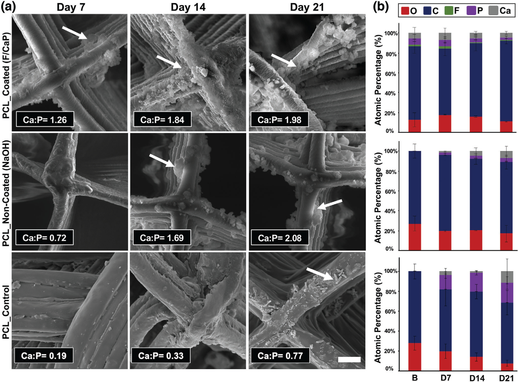
Morphological and chemical (elemental) analyses of MEW PCL scaffolds after SBF immersion. a) Representative SEM images and EDS semi-quantitative chemical analyses of F/CaP-coated, noncoated, and pristine scaffolds immersed in SBF at 37 °C for 7, 14, and 21 days. The red arrows indicate apatite formation. b) Atomic wt% of crystals deposited on surfaces of all groups (carbon (blue), oxygen (red), calcium (gray), phosphorous (purple), fluorine (green).
Complementary to that, Figure 5a shows the FTIR spectra of pristine (control), noncoated (NaOH-etched), and coated scaffolds immersed in SBF for 3 weeks, which also indicated suggestive peaks of crystalline apatite formed on the coated and the noncoated (NaOH-etched) scaffold counterpart. It should be highlighted that the PO43− ions’ main vibration bands, located ≈1100 cm−1, are overlapped with the PCL main characteristic bands. However, the emerged PO43− absorbance at ≈950–1100 and 550–620 cm−1 and the intensity of these bands increased with longer SBF immersion time. These observations are characteristic of fluorapatite and hydroxyapatite.[29] On the other hand, the carboxylate groups, formed on the noncoated scaffolds due to NaOH etching, were not sufficient to induce apatite nucleation, since less prominent bands were identified later between 14 and 21 days. The same pattern was evidenced with pristine PCL scaffolds, suggesting limited bioactivity. Additionally, the PCL peaks tended to decrease as the incubation time increased, due to partial hydrolysis of their organic component. This process is more evident for the C═O absorption peak at ≈1720 and ≈1100 cm−1 and it became more noticeable as SBF immersion time increased. Importantly, the presence of OH− and PO43− on the surface of the F/CaP scaffolds, and the presence of a negatively charged surface, possibly attracted Ca2+ from SBF, leading to the formation of Ca-rich CaP; and the process continued as the presence of calcium aggregation attracted more PO43− [24]
Figure 5.
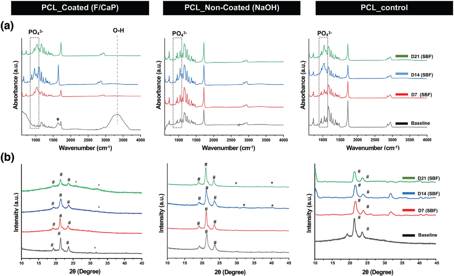
Chemical analyses of the F/CaP-coated, noncoated (NaOH-etched), and pristine scaffolds after SBF immersion. a) FTIR data show the chemical functional groups related to apatite formation on the surface of the fibers of the distinct scaffolds. b) XRD data reveal peaks associated with apatite after SBF immersion for F/CaP-coated, noncoated (NaOH-etched), and pristine scaffolds. (# PCL, * apatite, and ◊ carbonated apatite).
XRD patterns of F/CaP-coated, noncoated (NaOH-etched), and pristine PCL scaffolds before and after SBF immersion are shown in Figure 5b. A typical PCL pattern was shown in the ≈20° and ≈24° in pristine PCL, F/CaP-coated, and NaOH-etched scaffolds. After soaking in SBF, the F/CaP-coated group developed a broad peak in the range of 15°–25°, which should belong to the amorphous phase with small, weak crystallite, which illustrates that ion that precipitate gradually accumulates on the initial surface and belongs to hydroxyapatite that gradually decreases with increasing soaking time in SBF. Noncoated (NaOH-etched) and pristine PCL scaffolds showed peaks at 31°–33°, which can be attributed to apatite formation. However, the peaks appearing at 32° that belonged to hydroxyapatite disappeared at day 21 in pristine PCL, which can indicate nonstable crystalline phase precipitation, and it might be related to weakly formed apatite as a result of the absence of -COOH on the surface of PCL. In contrast, although no clear peak at ≈31° was evidenced in F/CaP-coated scaffolds at 7 days, after 2 weeks, a discrete peak appeared and increased after 21 days. These peaks are ordinarily associated with dicalcium phosphate dehydrate, a possible bone substitute and nucleation precursor.[37] Thus, due to the formation of this new phase of crystalline CaP, we can state that the F/CaP-coated scaffolds are bioactive.
2.3. Effect of F/CaP-Coated MEW PCL Scaffolds on Cell Compatibility and Function
From a cell compatibility standpoint, hPDLSCs seeded on F/CaP-coated scaffolds show a significant increase in proliferation compared to noncoated scaffolds at day 3 through 14 (Figure 6a,b), thus attesting to the cytocompatible character of the developed coating. Further, qualitative assessment of the role of F/CaP-coated scaffolds on cell attachment and proliferation was performed using CLSM and SEM imaging. Over time, DAPI (4′,6-diamidino-2-phenylindole)/phalloidin staining, along with SEM images, demonstrate hPDLSCs initially attached to the walls of the scaffold, and then to the corners of each individual strand, ultimately led to complete scaffold coverage (Figure 6c,d). Focal adhesion points were prominent between cells and adjacent fibers and were more evident in the F/CaP-coated scaffolds (Figure 6d).[38]
Figure 6.
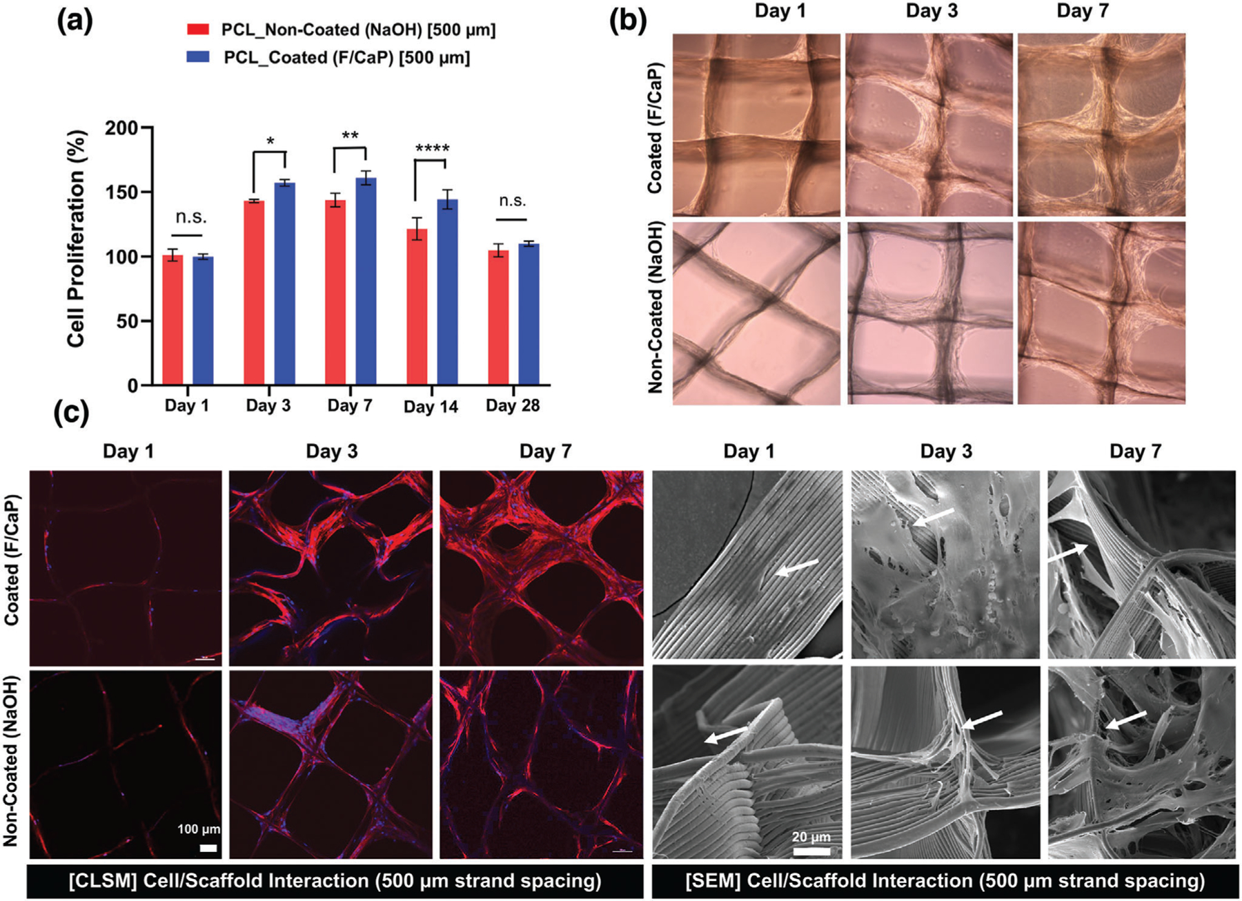
Attachment and proliferation of hPDLSCs on MEW PCL scaffolds. a) Cell proliferation on F/CaP-coated and noncoated scaffolds (500 µm strand spacing) using alamarBlue assay over 28 days. Mean ± SD (n = 3). ANOVA: ***p < 0.001, **p < 0.01, *p < 0.05. b) Optical microscopy images of F/CaP-coated and noncoated scaffolds during in vitro culture, indicating a gradual enhanced proliferation. c) Confocal microscopy images show significant cell bridging in 500 µm F/CaP-coated scaffolds at day 7. DAPI (blue) and phalloidin (red) fluorescent staining of hPDLSCs seeded on MEW PCL scaffolds (scale bar = 100 µm) and representative SEM images of hPDLSCs proliferation on F/CaP-coated and noncoated scaffolds after 7 days. Note the characteristic cell spreading along the fibrous walls of the scaffolds. A more pronounced spreading was detected along the nanostructured F/CaP-coated scaffolds (white arrows indicate important filopodia protrusion along and around the fibers).
In this work, we hypothesized that the developed F/CaP nanostructured coating on the highly ordered scaffolds could enhance the osteogenic differentiation of hPDLSCs. hPDLSCs were seeded on coated and noncoated scaffolds and cultured in both basal and osteogenic conditions. At day 14, higher alkaline phosphatase (ALP) activity was detected in the coated scaffolds cultured in basal media when compared to their noncoated counterpart cultured under the same conditions (Figure 7a). This finding indicated that the coating provided the hPDLSCs the needed supplements to guide osteogenic differentiation. Furthermore, the F/CaP coating not only upregulated ALP activity, but also thrust hPDLSCs into forming mineralized nodules (Figure 7b).
Figure 7.
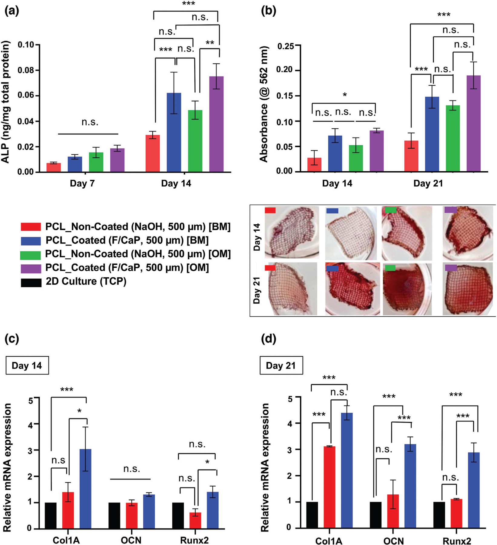
Osteogenic differentiation by means of ALP activity, quantification of mineralized nodule formation using Alizarin red staining (ARS), and gene expression of osteogenic markers. a) ALP activity after 7 and 14 days for hPDLSCs seeded on F/CaP-coated scaffolds was significantly higher than noncoated scaffolds in basal (BM) and osteogenic (OM) culturing conditions. b) ARS quantification and optical images of hPDLSCs seeded on F/CaP-coated, scaffolds in both BM and OM were significantly higher than noncoated (500 µm strand spacing) scaffolds after 14 and 21 days. c,d) The mRNA levels on day 14 and day 21 of selected osteogenic markers were significantly higher in the F/CaP-coated scaffolds than those in their noncoated counterparts. Mean ± SD (n = 3). ANOVA: ***p < 0.001, **p < 0.01, *p < 0.05.
Alizarin red staining (ARS) was used to identify mineralized matrix deposition. Worth noting, at days 14 and 21, hPDLSCs seeded on the coated scaffolds and cultured in basal media led to similar mineralization, when compared to the noncoated group cultured in osteogenic conditions. Remarkably, this observation further indicates the role of the nanostructured coating as the predominant driving force for cellular commitment toward osteogenic differentiation. This was further confirmed through osteogenic gene expression for Runx2, Col 1, and OCN. At the early stage of osteoid matrix deposition in bone, Col 1 forms the major matrix component of ECM, whereas, in later stages, OCN is highly expressed by bone-forming cells. Additionally, Runx2 is the major regulator of BMP signaling that evokes the commitment of osteogenic differentiation, all of which was significantly upregulated at 14 and 21 days post-seeding in the coated scaffolds compared to hPDLSCs cultured in osteogenic media or on noncoated scaffolds (Figure 7c). Overall, our nanostructured F/CaP coating promoted significant osteogenic differentiation of hPDLSCs as indicated by greater ALP activity, robust mineral deposition, and the upregulation of bone-related genes in the absence of osteogenic inducers.[4,39] Previous reports have demonstrated that CaP coatings can boost osteogenic gene expression and ALP activity in bone cells, as well as cell attachment ability and proliferation in vitro.[13] Furthermore, calcium and phosphorus ions have shown the ability to modulate osteoclast and osteoblast activity in vivo, due to their similarity to inorganic mineral phase crystals contained in bone.[13,40]
2.4. Effect of F/CaP-Coated MEW PCL Scaffolds on Biofilm Inhibition
Fluorinated hydroxyapatite coating has been reported to exhibit higher antimicrobial activity against bacteria, such as P. gingivalis and S. aureus, than pure hydroxyapatite.[41] Moreover, the effect of surface topography on bacterial adhesion and biofilm formation has been vastly investigated.[42–46] Briefly, it is believed that the surface roughness and chemical composition of the coating influence bacterial adhesion.[47] Thus, we examined the antimicrobial potential of our nanostructured F/CaP-coated scaffolds against P. gingivalis. Our data (CFU mL−1) indicated minor, yet significant, action against P. gingivalis. AFM images demonstrated that while the surface of pristine PCL was the smoothest, both NaOH etching and the F/CaP-coating increased the roughness of the respective fibers (Figure 2). Surprisingly, the greater surface roughness presented by fibers of F/CaP-coated scaffolds did not increase bacterial adhesion and was similar to that exhibited by generally hydrophobic PCL scaffolds (Figure 8a). We ponder that the fiber roughness of NaOH-etched scaffolds favored bacterial growth, which led to the highest bacterial counts. SEM images showed a significant amount of bacteria-forming microbial biofilms after 2 days of bacteria inoculation in NaOH-etched scaffolds, agreeing with the numerical (CFU mL−1) findings. SEM images for both the pristine PCL and F/CaP-coated groups indicated a reduced number of viable bacteria compared to the NaOH-etched scaffolds (Figure 8b). The reduced bacterial growth, even with a rougher surface, suggests an antimicrobial action due to the coating composition, as fluoride has been shown to affect bacterial metabolism.[41,48,49] Indeed, as previously highlighted by Gristina et al. in the “race for the surface” concept, where both host cells and bacteria compete to colonize implanted biomaterials,[48] here, our F/CaP-coated scaffold demonstrated bioactive, osteogenic, and antimicrobial features, critical to regenerate tissues in infection-driven diseases. Nonetheless, future experiments focusing on amplifying the antimicrobial efficacy are warranted.
Figure 8.
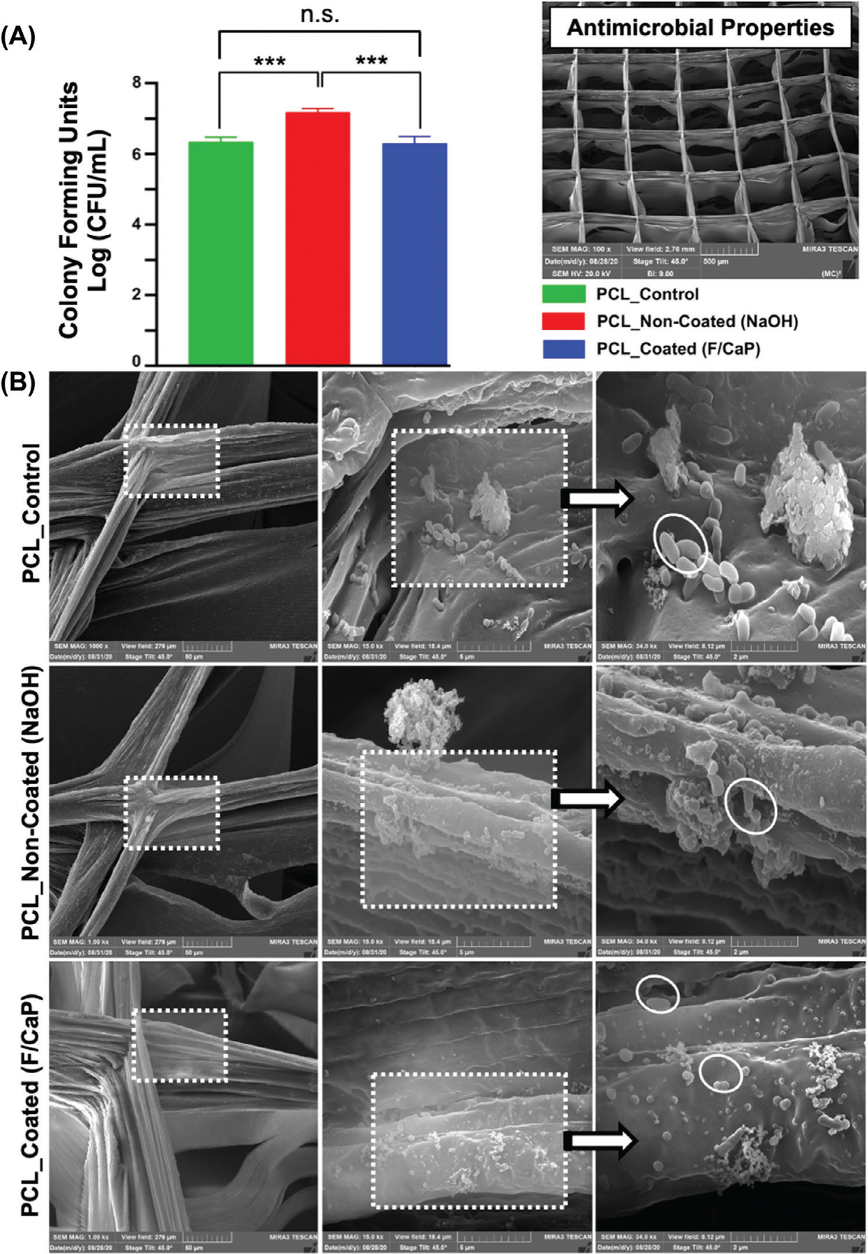
a) Colony-forming unitsin broths of Gram-negative bacteria, P. gingivalis grown on pristine PCL, noncoated, and F/CaP-coated scaffolds. Mean ± SD (n = 6). ANOVA: ***p < 0.001, **p < 0.01, *p < 0.05. b) Representative SEM images of 2 days P. gingivalis biofilm formation, demonstrates that bacteria attach to the scaffolds’ surface of different groups.
2.5. Biocompatibility of F/CaP-Coated MEW PCL Scaffolds
It is known that in vivo biocompatibility determines the long-term outcome of implanted scaffolds. Therefore, to determine the overall biocompatibility of the fabricated F/CaP-coated scaffolds, first, a well-established subcutaneous model was used to explore cellular infiltration properties, morphological changes of the implanted scaffolds over time, blood vessel formation, and potential inflammatory cell response elicited by the engineered scaffolds due to their composition and/or degradation byproducts. Hematoxylin and eosin (H&E) images of retrieved and histologically processed scaffolds (i.e., coated, noncoated, and thermal polymer extrusion, TPE) are shown in Figure 9.
Figure 9.
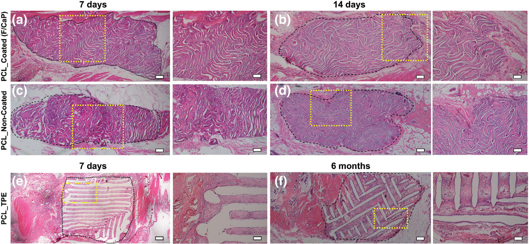
Panoramic view (scale bar = 200 µm) and 4x magnification (scale bar = 100 µm) of representative H&E staining of the implanted scaffolds of a,b) F/CaP-coated and c,d) noncoated scaffolds after 7 days and 14 days, respectively, compared to e,f) polymer thermal extrusion (PTE) after 7 days and 6 months. Black dashed lines delineate the implanted scaffold border, highlighting the tissue ingrowth over time.
A mixture of fibrin and connective tissue fibers, combined with a low extent of mononuclear cells, was observed within the explanted (7 days) scaffolds, i.e., F/CaP-coated and noncoated scaffolds. For both coated and noncoated scaffolds, host cells recognized the small diameter fibers as their initial attachment sites to align themselves and start the formation of collagenous ECM (Figures 9 and 10) over 28 days. In contrast, in TPE scaffolds, due to their large fiber diameter, a more scattered pattern of cell distribution was seen. In Figure 9, a significant ingrowth of host tissues can be noticed throughout the MEW scaffolds, with no observable signs of inflammation being detected at this early timepoint. Starting at day 14 post-implantation, the scaffolds of each group were integrated within tissue and the composition of this tissue was similar at day 28 (Figure 10). Blood vessel ingrowth into F/CaP-coated, noncoated, and TPE scaffolds was observed. Blood vessel density increased from day 7 to day 28 in MEW scaffolds due to high porosity (Figure 10). Interestingly, blood vessel infiltration was apparently higher in F/CaP-coated scaffolds, indicating that vascularization and cell invasion was enhanced in the presence of the nanostructured coating. Furthermore, blood vessel invasion not only occurred within strands, but also within strand walls in the coated scaffolds. It has been reported that the release of Ca ions from CaP-coated scaffolds prompts endothelial progenitor cells and provokes the release of vascular endothelial growth factor via calcium-sensing receptor activation.[50,51]
Figure 10.
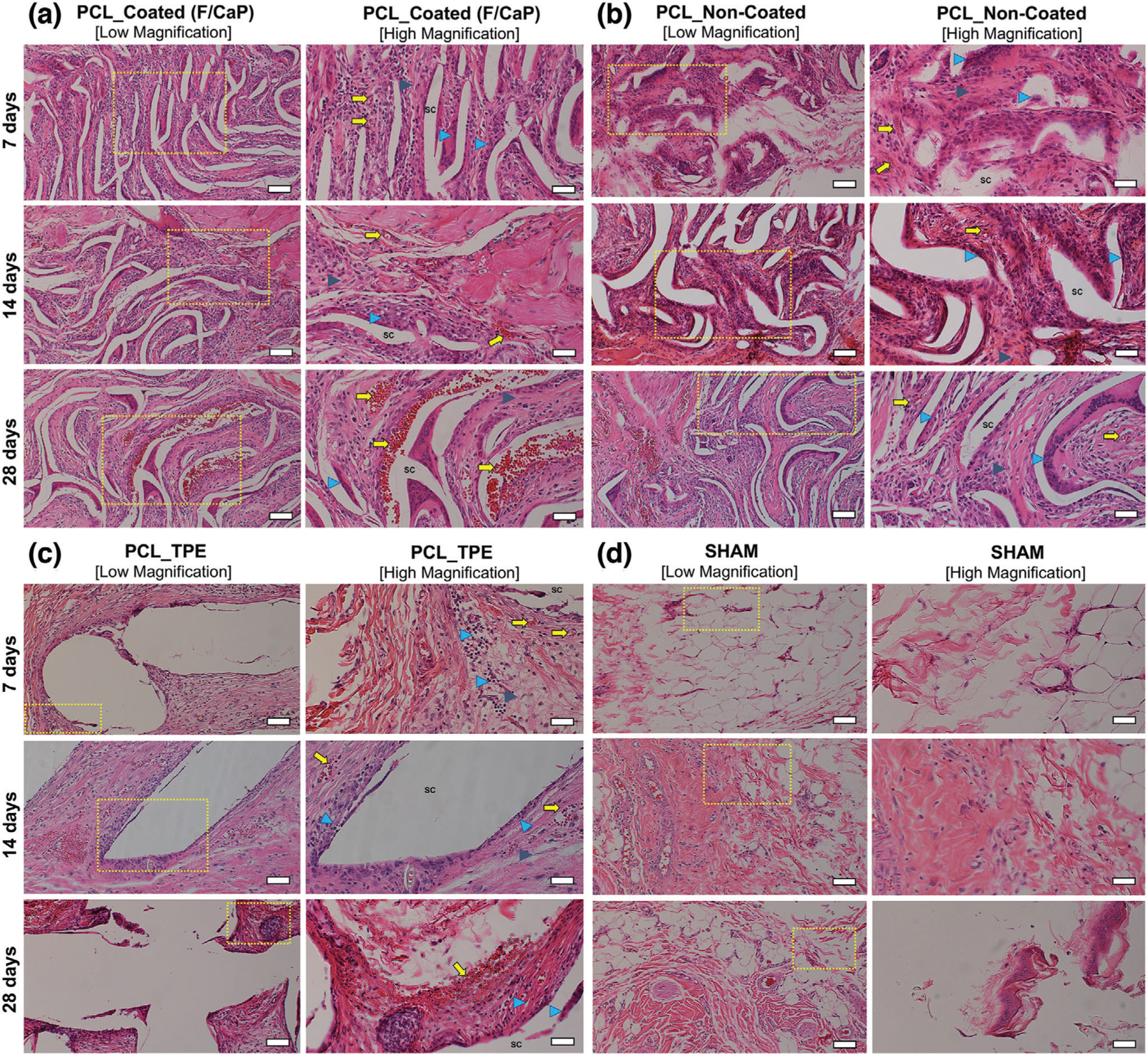
Representative H&E staining and histological analysis of the implanted scaffolds. a) F/CaP-coated, b) noncoated, c) polymer thermal extrusion (PTE), and d) sham–control after 7, 14, and 28 days in vivo (10 × [low magnification, scale bar = 50 µm] and 20 × [high magnification, scale bar = 25 µm]). Scaffold: Sc, Blood vessels: yellow arrow, Inflammatory cells: blue arrowhead; and Fibroblasts: gray arrowhead.
2.6. In Vivo Evaluation of F/CaP-Coated MEW/PCL Scaffolds Regenerative Capacity
Based on important in vitro findings, where the presence of the nanostructure F/CaP coating promoted significant osteogenic differentiation of hPDLSCs in the absence of chemical inducers, in addition to in vivo biocompatibility, we next pursued a clinically relevant, proof-of-concept in vivo study to examine the regenerative potential of the F/CaP-coated scaffolds. To that end, a well-established fenestration defect model[52,53] has been widely used to define the therapeutic efficacy of novel scaffolds and provide suitable clinical insight and a proof-of-concept prior to the larger animal model,[54] was used to mimic a clinical scenario of periodontal destruction (Figure 11a).
Figure 11.
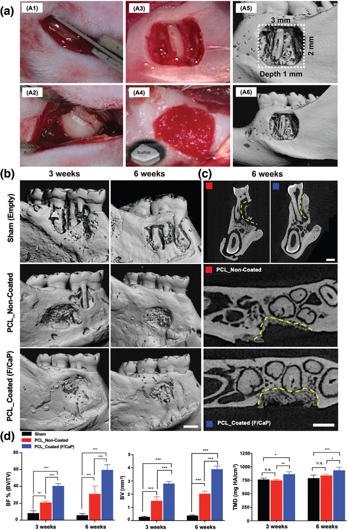
a) Generation and characterization of rat mandibular periodontal fenestration defect model. a1–a3) Macrophotographs of a rat mandible after the incision, flap elevation, creation of the defect. a4) Implantation of F/CaP-coated scaffold in the defect, it has the ability to absorb of blood instantly and acts as clot retention. a5,a6) Micro-CT 3D reconstruction images show the 3 × 2 mm × 1 mm standardized defect on the buccal side of the first and second molars of the rat. The distal root of the mandibular first molar was exposed in the middle of the defect. b) Representative micro-CT images of the fenestration defect exposing the distal root of the first molar and the mesial root of the second molar at 3 and 6 weeks in the control, noncoated, and F/CaP-coated groups. c) 2D cross-sectional and transverse views highlight the visual differences between the area and density of bone regenerated within the defect (indicated by yellow lines). Scale bar = 1 mm. d) Micro-CT assessments of bone volume, bone fill, and tissue mineral density at 3 and 6 weeks post-implantation within different groups. The F/CaP-coated group showed significant differences for bone volume and bone fill compared to both noncoated and control groups. Mean ± SD (n = 4). ANOVA: ***p < 0.001, **p < 0.01, *p < 0.05.
Micro-computed tomography (micro-CT) and histological analyses showed that bone formation after 3 and 6 weeks post-implantation was significantly enhanced in defects treated with F/CaP-coated scaffolds, compared with noncoated scaffolds and nontreated (sham) defects (Figures 11 and 12). At 3 weeks, bone volume (BV), bone fill (BV/TV), and tissue mineral density (TMD) were significantly higher in F/CaP-coated scaffolds compared to the other groups. The percent of bone fill, which indicates the amount of newly formed bone, was higher (with statistical significance p < 0.001) in F/CaP-coated scaffolds than in the noncoated and sham groups (Figure 11d). Similarly, by comparison, micro-CT data after 6 weeks revealed that bone volume (BV, TMD, and (BV/TV)) in F/CaP-coated scaffolds was significantly higher and demonstrated nearly complete bone coverage of the tooth roots compared to other groups. The 2D micro-CT images showed that F/CaP-coated scaffolds were able to maintain PDL space similar to the nontreated lingual side. In this work, our F/CaP-coated scaffold was able to physically maintain the defect site and support infiltration and attachment of host progenitors capable of supporting the simultaneous and coordinated growth of both soft and hard periodontal tissues.
Figure 12.
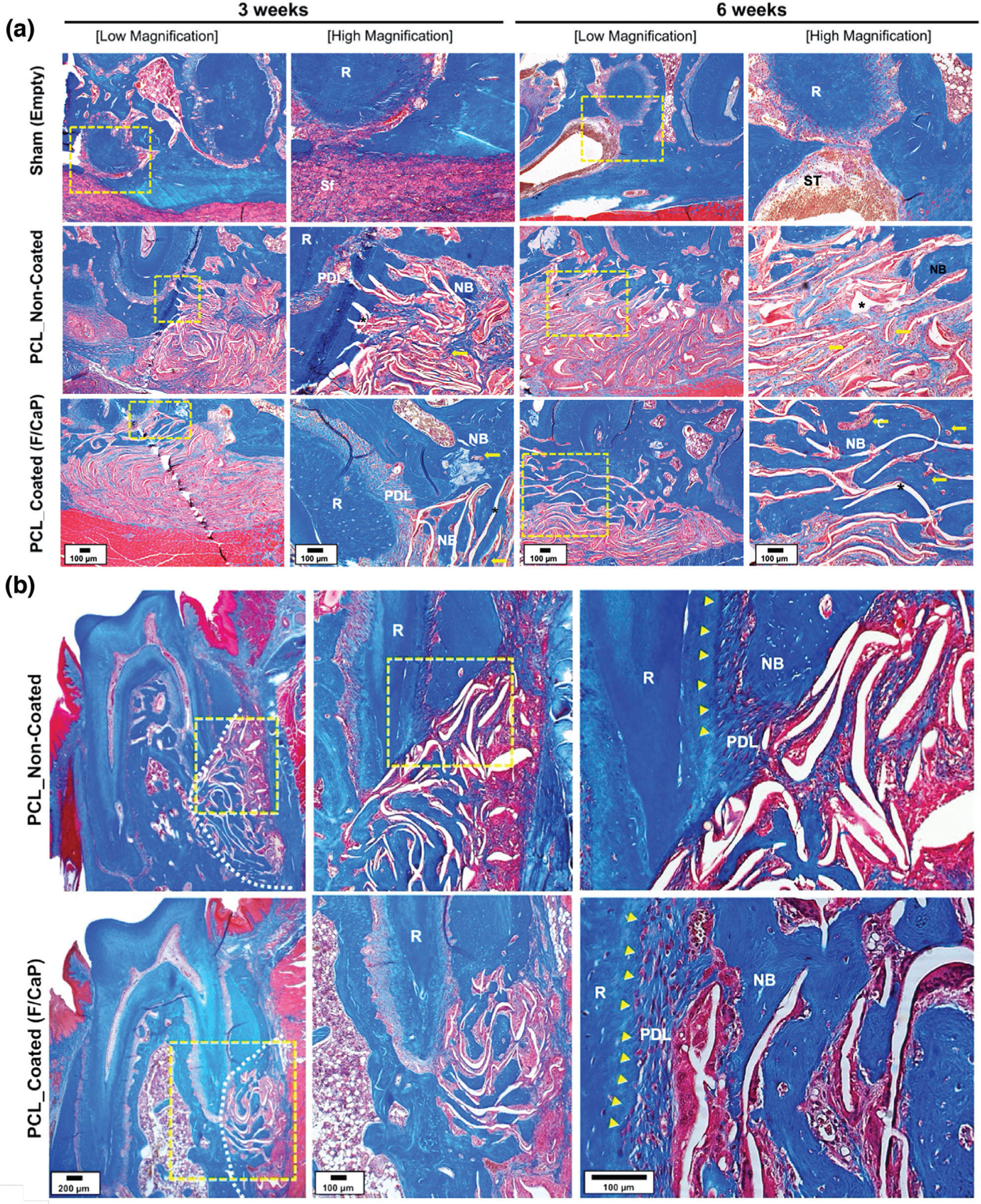
a) Representative MT-stained horizontal cross-sections of noncoated and F/CaP-coated scaffold-treated defects at 3 and 6 weeks post-implantation. Photomicrographs of the defect area show newly formed bone and PDL. b) Representative MT-stained longitudinal sections of noncoated and F/CaP-coated scaffold-treated defects at 6 weeks post-implantation. Analyses for periodontal regeneration on the tooth-root surface indicated neo-tissue formation and Sharpey’s fiber insertions to new bone and cementum. White dotted line: defect site; yellow arrows: vascularization; asterisks (*): scaffold, yellow arrowhead: cementum; New bone: NB; Root surface: R; Periodontal ligament: PDL; and Soft tissue infiltration: Sf.
Detailed Masson’s trichrome (MT) histological analysis demonstrated that the F/CaP-coated scaffold led to the regeneration of new alveolar bone, cementum, and PDL as early as 3 weeks post-implantation (Figure 12a). Highly porous and micron-sized fibrous scaffolds allowed for an increase in vascularization and simultaneously supported multi-tissue periodontal regeneration (Figure 12a). Compared to previous observations, the bulky nature and lack of adequate interconnected pores in scaffolds prepared via SLS impaired wound healing and led to subsequent microbial contamination.[8]
Of note, our findings corroborate with a previous study reported by Abbasi et al. in 2020, demonstrating that while the most favorable initial cell (osteoblasts) attachment was found on small pore size (250 µm) and gradients scaffolds, larger (500 µm) pore size resulted in faster repair of critical-sized calvaria bone defects.[15,55] Indeed, our data are supported by the fact that a scaffold with sufficient porosity (500 strand spacing) and pore interconnectivity is needed for vascularization, cellular infiltration, and ultimately improved bone formation. Concomitant with that, the unique structure and associated porosity of the F/CaP-coated scaffolds obtained via MEW led to significantly higher amount of regenerated bone at both time points. Noteworthy, at 6 weeks post-implantation, the representative MT-stained images revealed new osteoblasts lining the organic matrix and osteocytes trapped in the lacunae of newly formed alveolar bone infiltrated with blood vessels. Moreover, newly formed connective tissue fibers were found deposited along the root dentin surface, in an orientation resembling physiologically healthy PDL (Figure 12b). Meanwhile, noncoated MEW PCL scaffolds displayed more collagenous, nonmineralized tissue and more soft tissue infiltration (Figure 12b). Altogether, the engineered F/CaP-coated MEW PCL scaffolds contributed to a more robust and hierarchically organized periodontal complex of both soft (PDL) and hard (alveolar bone and cementum) tissues when compared to the noncoated scaffolds.
From a clinical standpoint, although existing therapeutics can lead to some degree of tissue regeneration, the low predictability and efficacy in cases of extreme tissue destruction call for improved strategies that can better replicate the 3D and multi-tissue complexity of periodontal defects.[56] Precisely, currently, there are no approaches to predictably regenerate defects with considerable bone loss while avoiding tooth extraction. In previous work, a biphasic scaffold was engineered through the combination of fused deposition modeling to obtain an osteoconductive bone compartment using 𝛽-TCP/PCL and a periodontal ligament compartment using melt electrospinning to support PDL cell sheets.[46] Large pore size permitted vascularization of the cell sheets, and periodontal attachment was achieved at the dentin interface. Similarly, Criscenti et al. converged 3D-printed PCL scaffolds and poly(lactic-co-glycolic acid) electrospun nanofibers to develop a triphasic scaffold aimed at mimicking the bone-to-ligament interface.[57] Although the collective results from that study demonstrated that the combination of electrospinning and 3D printing represents a promising approach for the fabrication of scaffolds for the regeneration of periodontal tissue interfaces, multiple techniques are required to fabricate each tissue-specific compartment, thus leading to additional processing steps to integrate them into a single scaffold. In our work, a highly ordered and osteoconductive scaffold that stimulates alveolar bone regeneration while serving as a barrier membrane, thus allowing resident progenitor cells to regenerate new periodontal ligament and cementum when implanted in a well-established periodontal defect model, certainly represents the first step toward the development of personalized scaffolds capable of enabling tissue-specific differentiation of progenitor cells, thus guiding the simultaneous and coordinated regeneration of soft and hard periodontal tissues. Nonetheless, even though the fenestration defect model utilized herein provides meaningful clinical insight, future in vivo studies in larger animal models are necessary to determine both the regenerative and antimicrobial efficacy in vivo.
3. Conclusions
We believe that this work will contribute to the development of personalized and defect-specific scaffolds for periodontal regeneration capable of enabling the differentiation of resident progenitor cells, and thus guide the coordinated growth of soft and hard periodontal tissues, while affording antimicrobial properties.
4. Experimental Section
Materials:
PCL (Mn: 5000) was procured from CELLINK (Göthen-burg, Sweden). All other chemical reagents and solutions were purchased from Sigma-Aldrich (St. Louis, MO, USA), unless otherwise noted—sodium hydroxide (NaOH, ≥ 98%), ethanol (99.5%), ethylenediaminetetraacetic acid calcium disodium salt (EDTA-Ca), potassium phosphate (KH2PO4, ≥ 99%), and potassium fluoride (KF, ≥ 99.9%). Hexamethyldisilazane (HMDS, ≥ 99%), hexadecylpyridinium chloride monohydrate (CPC), paraformaldehyde (PFA), sodium chloride (NaCl), sodium bi-carbonate (NaHCO3), potassium chloride (KCL), potassium phosphate dibasic trihydrate (K2HPO4⋅3H2O), magnesium chloride, hexahydrate (MgCl2⋅6H2O), calcium chloride (CaCl2), sodium sulfate (Na2SO4), tris-hydroxymethylaminomethane [(CH2OH)3CNH2], and hydrochloric acid (HCl) were used as-received without any further purification. Milli-Q deionized water from a Millipore Milli-Q ultrapure water system (MilliporeSigma, Burlington, MA, USA) was used in the experiments. Phosphate-buffered saline (PBS) was procured from GIBCO Invitrogen (Carlsbad, CA, USA). Meanwhile, a 15% heat-inactivated fetal bovine serum (FBS) solution, alfa-minimum essential medium (𝛼-MEM), and a 1% penicillin–streptomycin solution, were purchased from HyClone (Life Technologies Corporation, Gibco/Brl Division, Grand Island, NY, USA). Also procured were Dispase II (Cat #04942078001, Roche Diagnostics, Indianapolis, IN, USA), collagenase type II (Cat #LS004196, Worthington Biochemical Corp., Lakewood, NJ, USA), and ascorbic acid-2 phosphate (Sigma-Aldrich).
MEW and Scaffold Design:
PCL is an FDA-approved polymer extensively used to fabricate scaffolds for bone tissue engineering due to its general biocompatibility and well-known degradability pattern in vivo.[58] Here, PCL scaffolds were fabricated via MEW using a multi-head bioprinting platform (3DDiscovery, regenHU Ltd., Villaz-St-Pierre, Switzerland) in a biosafety cabinet. The bioprinting system was designed to move on the x, y, and z axes with a printhead moving in the x and z direction and the collector platform moving in the y direction. Specifically, the MEW printhead was supplied with high-voltage power, a pneumatically regulated feeding system, and an electrical heating system to control the temperature of the metal cartridge that housed the polymer (PCL) pellets. The printing path designs were created using BioCAD; a G-code file was generated and loaded to HMI software for printing. In brief, PCL pellets were placed inside the metal cartridge capped with a 26G nozzle, then heated to 90 °C for 30 min to allow enough time for the polymer to melt homogenously. The system’s pressure was optimized to 0.07 MPa.[14] The various scaffolds were printed at a feed rate of 40 mm s−1 and −7 kV of voltage at a distance of 4 mm from the collector. The 0/90° crosshatch design, having 500, 750, and 1000 µm strand spacings, was printed on top of each other to form scaffolds with 450 layers. The MEW process was conducted at an ambient temperature of 21.5 °C and a humidity level of ≈38.5%. In order to increase the hydrophilicity of PCL, the scaffolds were etched in a 5 m NaOH aqueous solution according to a previously reported method.[59] First, the scaffolds were washed with 70% ethanol for 15 min, then they were immersed in the aforementioned NaOH solution at room temperature (RT) for 4 h. After etching, the scaffolds were thoroughly rinsed with deionized (DI) water to neutralize the pH and left to air-dry overnight. Subsequently, the F/CaP coating process was performed using a modified method described elsewhere.[60] In brief, the MEW scaffolds were immersed in a solution that had a mixture of 0.10 m EDTA-Ca, 0.06 m KH2PO4, and 0.02 m KF and were incubated under ambient pressure at 37 °C for 24 h. Finally, the scaffolds were gently taken out and washed with PBS and left to air-dry overnight. For comparison purposes, 3D-printed PCL scaffolds (8 × 8 mm2, 0.45 mm thick, and 500 µm strand spacing) were produced via thermal polymer extrusion (TPE). In brief, PCL pellets were heated to 90 °C for 30 min, then polymer melt was extruded via a 26G nozzle under pressure of 0.6 MPa and a feed rate of 0.5 mm s−1.
Morphological and Chemical Analyses:
The morphology of the processed MEW PCL scaffolds (i.e., nonetched, etched with NaOH, and etched with NaOH and F/CaP-coated) was investigated using an SEM (MIRA3, FEG-SEM, TESCAN Brno, Kohoutovice, Czech Republic) equipped with an energy dispersive spectroscopy (EDX, Tescan MIRA3 FEG-EDAX) system to determine the chemical composition of the F/CaP coating. The scaffolds were mounted on Al stubs using double-sided adhesive carbon tape, and then a thin layer of Au was sputter-coated for 60 s (SPI-Module Carbon/Sputter Coater, Thermo Fisher Scientific Inc., West Chester, PA, USA) prior to SEM imaging. Fibers (n = 30) were analyzed in order to calculate their diameter using ImageJ software (National Institutes of Health, Bethesda, MD, USA). Then, a quantitative porosity analysis of the scaffolds was performed.[61,62] In brief, representative SEM images for each scaffold (n = 5 per group) were imported into the ImageJ software (National Institutes of Health) and processed into 8-bit files. After thresholding, the images were ready for analysis. As a result, the thresholding area represented the scaffold, and the spacing was determined using the command “Analyze → Measure.” AFM was performed using a TT-AFM equipment (AFM Workshop, Hilton Head Is- land, SC, USA) in contact mode to investigate the scaffolds (i.e., pristine, noncoated, and F/CaP-coated) in terms of fiber morphology and surface roughness. Qualitative fiber roughness along the fiber long axis was determined from 10 × 10 µm images (n = 4 per group) using Gwyddion Software (version 2.56, Czech Metrology Institute, Jihlava, Czech Republic). To identify the presence of specific chemical groups on the MEW PCL scaffolds, FTIR was used to determine the effects of etching, as well as the F/CaP coating on the scaffolds and study interactions between the F/CaP coating and the polymer surface. 16 scans with spectra between 600 and 4000 at 4 cm−1 resolution were recorded using an FTIR instrument in the attenuated total reflectance mode (ATR-FTIR, Thermo-Nicolet iS-50, Thermo Fisher Scientific, Inc.). Baseline correction spectra were then centered and normalized for analysis. Meanwhile, the structure and phase composition of the scaffolds were also investigated by XRD (Rigaku Ultima IV diffractometer, Rigaku Americas Corporation, Woodlands, TX, USA) with Cu K𝛼 (𝜆 = 1.54 Å) in Bragg-Brentano geometry. The X-ray source and detector were coupled to scan in a 2-theta (2𝜃) range from 5° to 45° in a step size of 0.05° at a scan speed of 1° min−1. The phase identification was performed using Rigaku’s data analysis software (PDXL Version 2.6.1.2) and the Inorganic Crystal Structure Database (ICSD). The thermal properties of F/CaP-coated, noncoated, and pristine MEW PCL scaffolds were examined with DSC (Perkin-Elmer DSC-7, Perkin-Elmer Inc., Waltham, MA, USA) and TGA (Perkin-Elmer TGA-7, Perkin-Elmer Inc.). For DSC measurements, the scaffolds were mounted in copper DSC pans, held isothermally at 25 °C for 1 min and heated from 25 to 650 °C. Similarly, for TGA, the samples were heated to 650 °C at a rate of 10 °C min−1 and a nitrogen atmosphere. The chemical stability of F/CaP-coated scaffolds was examined post-incubation in distilled water (dH2O) and SBF. F/CaP-coated scaffolds (n = 3) were immersed in 10 mL dH2O at 37 °C. After soaking for 1, 3, and 7 days, the release of Ca and P ions was determined using high-resolution ICP-MS (Quadrupole-ICP-MS, Thermo Fisher Scientific, Inc., Waltham, MA, USA). Further, thermal properties and stability of the mineral phase of F/CaP-coated scaffolds after soaking in dH2O and SBF were examined using TGA, at 3 and 7 days post-incubation. The samples were heated to 600 °C at a rate of 10 °C min−1 and a nitrogen atmosphere, and the percentage of residual mass was measured at 550 °C.
Biomechanical Properties:
The mechanical properties, namely, tensile strength, Young’s modulus, and elongation at break of F/CaP-coated, noncoated (NaOH-etched), and pristine PCL (500 µm strand spacings), were assessed by uniaxial tensile testing (expert 5601, ADMET, Inc., Norwood, MA, USA). Rectangular-shaped scaffolds (15 mm × 3 mm × 0.45 mm) were evaluated (n = 4 per group) at a crosshead speed of 2 mm min−1. Mechanical data of each sample were acquired from the stress–strain curves and reported in MPa.
In Vitro Bioactivity:
The in vitro bioactivity test was carried out by suspending the distinct scaffolds vertically in a well-established SBF solution prepared according to the method described by Kokubo et al.[63,64] In brief, 8.035 g NaCl, 0.355 g NaHCO3, 0.255 g KCL, 0.231 g K2HPO4⋅3H2O, 0.311 g MgCl2⋅6H2O, 0.292 g CaCl2, and 0.072 g Na2SO4 were dissolved in 1 L of dH2O under continuous stirring at 36.5 °C and buffered at pH 7.4 with tris-hydroxymethylaminomethane [(CH2OH)3CNH2] and 1 m hydrochloric acid (HCl). Then, the SBF was stored at 4 °C to be used within 30 days of preparation. Next, F/CaP-coated, noncoated (NaOH-etched), and pristine MEW PCL scaffolds (n = 3 per group per timepoint) were soaked in 8 mL of SBF under 120 rpm shaking speed at 37 °C and retrieved at different time intervals up to 21 days. Noncoated and pristine MEW scaffolds were used as controls. At the end of each time point, the scaffolds were gently taken out and rinsed with DI water, then left to air-dry overnight. Finally, chemo-morphological analyses were carried out by SEM/EDS, FTIR, and XRD (as mentioned above).
Cell Culture:
hPDLSCs previously isolated and characterized for (CD90+ and CD105+)[65] were used in the experiments reported herein. Briefly, human PDL tissues were scraped from the middle part of the root surface, then grown on 𝛼-MEM. Cells were then collected and centrifuged; the resultant supernatant was removed, and the cells were resuspended in PBS containing 4 mg mL−1 dispase II and 2 mg mL−1 collagenase type II for 60 min at 37 °C. The solution was inactivated with a mixture of 𝛼-MEM, FBS, and 100 × 10−6 m ascorbic acid 2 phosphate. The cells were cultured in T-25 flasks and the medium was changed every other day. For purposes of our experiments, hPDLSCs at passage 4 were expanded in 𝛼-MEM basal medium supplemented with 15% heat-inactivated FBS and 1% antibiotic/antimycotic solution. hPDLSCs were cultured at 37 °C at a 5% CO2 atmosphere. For the osteogenic differentiation assays, hPDLSCs were cultured in osteogenic differentiation media (OM) (i.e., basal medium supplemented with 50 µg mL−1 ascorbic acid, 10 × 10−3 m of 𝛽-glycerophosphate, and 10−8 m of dexamethasone). hPDLSCs cultured in basal media (BM) were used as the control. Of note, for all cell-related experiments, the MEW PCL scaffolds were disinfected by soaking in 70% ethanol, followed by UV irradiation (30 min on each side).
Cell Proliferation:
hPDLSCs at passage 5 were harvested and seeded at a density of 6 × 10⁴ cells per scaffold (8 × 8 mm2) in 24-well low attachment plates (Corning Life Sciences, Tewksbury, MA, USA). To determine the role of the F/CaP coating on cell proliferation, alamarBlue assay (Invitrogen, Thermo Fisher Scientific, Inc.) was performed at selected time points over 28 days (n = 3 per group per time point). In brief, 10% of the alamarBlue assay reagent was mixed with 90% of the media; it was then added to each well and incubated for 3 h at 37 °C and 5% CO2. The dye incorporation was measured at 560 nm (excitation range is 540–570 nm) and an emission of 590 nm (emission range is 580–610 nm); using a fluorescence-based plate reader (SpectraMax iD3, Molecular Devices LLC, San Jose, CA, USA). Finally, each well was washed with PBS and replaced with fresh media.
Cell–Scaffold Interaction:
Confluent hPDLSCs at passage 5 were harvested and seeded on the MEW PCL scaffolds. Noncoated (NaOH-etched) scaffolds served as the control. Briefly, using low attachment 24-well tissue culture plates (Corning Life Sciences), 6 × 10⁴ cells/scaffold were seeded and cultured for 1, 3, and 7 days (n = 3 per group per time point). At each time point, the scaffolds were gently washed in PBS and the cells were fixed in 4% PFA. After 48 h, the scaffolds were first dehydrated in ascending ethanol concentrations (up to 100%), followed by incubation in hexamethyldisilazane (HMDS, Sigma-Aldrich) overnight. Finally, the constructs were mounted on Al stubs using double-sided adhesive carbon tape, and then a thin layer of Au was sputter-coated for 60 s (SPI-Module Carbon/Sputter Coater, Thermo Fisher Scientific Inc.) prior to SEM imaging.
Confocal Laser Scanning Microscopy:
Attachment and proliferation of hPDLSCs on F/CaP-coated and noncoated (NaOH-etched) MEW PCL scaffolds were assessed by imaging using an upright fluorescence microscope (Carl Zeiss Meditec AG, Jena, Germany) and CLSM (Eclipse-Ti, Nikon Corporation, Tokyo, Japan). Cell-scaffold constructs were fixed in 4% PFA for 30 min at 4 °C, then washed in PBS (3 × ). hPDLSCs were subsequently permeabilized using 0.1% Triton X-100 solution for 5 min. After PBS (2 × ) rinsing, the constructs were blocked using 1.5% bovine serum albumin (BSA) in PBS for 30 min and then stained with TRITC-conjugated phalloidin and DAPI (1:1200, MilliporeSigma) for 1 h at RT according to the manufacturer’s instructions. Finally, the constructs were gently rinsed (3 × ) in PBS to remove excess phalloidin conjugate and placed on a glass slide for observation under fluorescence and confocal microscopes.
ALP Activity:
The ALP activity of hPDLSCs seeded on MEW PCL scaffolds was measured using the colorimetric SensoLyte pNPP ALP kit (AnaSpec Inc., Freemont, CA, USA), following the manufacturer’s recommendations. First, the wells were washed with PBS, then lysed with Triton-X-100. 50 µL supernatant was transferred to a 96-well plate and incubated for 10 min at RT. Then, 50 µL of the pNPP reagent was added to the supernatant and allowed to react for 1 h at 25 °C. The absorbance was measured using a microplate reader (Spectra iD3) at 405 nm, followed by calculation of the total ALP activity based on an ALP standard of known concentration and normalized to total protein measured using a BCA protein assay kit (Thermo Fisher Scientific Inc.) (n = 3 per group per time point).
Alizarin Red Staining:
Mineralized nodule formation was measured using ARS (ScienCell Research Laboratories, Inc., Carlsbad, CA, USA). Cell-scaffold constructs were washed (3 × ) with PBS for 15 min at RT; they were then fixed with 4% PFA. Each well was washed with DI water, then stained with 1 mL of 40 × 10−3 m ARS for 30 min. Finally, a destaining procedure was performed for 15 min using 10% w/v CPC in 10 × 10−3 m sodium phosphate at pH 7.0. The absorbance was measured at 562 nm using a microplate reader (Spectra I D3) to quantify the ARS concentration (n = 3 per group per time point).
mRNA Expressions using Real-Time PCR:
The expression of osteogenic genes, namely, Osteocalcin (OCN, Hs01587814_g1), Runt-related transcription factor 2 (Runx2, Hs01047973_m1), Collagen alpha 1 (Col1A1, Hs00164004_m1), and housekeeping gene Glyceraldehyde 3-phosphate dehydrogenase (GAPDH, Hs02758991_g1), were evaluated by a quantitative polymerase chain reaction (qPCR). Briefly, the cells were harvested, and the total RNA was isolated (Purelink RNA Mini Kit, Invitrogen Corporation. Carlsbad, CA, USA). cDNA synthesis was then performed using iScript RT Supermix (Bio-Rad Laboratories, Inc., Hercules, CA, USA). The ΔΔCq method was used to measure the relative gene expression from the quantification cycle (Cq) values retrieved by qPCR analysis. Three independent PCR reactions were performed for each sample (n = 3 per group per time point). qPCR results were normalized to the reference sample.
Antimicrobial Character:
Colony-forming units (CFU mL−1) were quantified after growing Porphyromonas gingivalis (P. gingivalis) ATCC 33277 on the scaffolds for 48 h. In brief, the MEW PCL (pristine, noncoated, and F/CaP-coated) scaffolds (8 × 8 mm2 and 0.45 mm thick) were adapted in CellCrown inserts (Scaffdex Ltd., Tampere, Finland), then kept under UV light for 30 min per each side. The set was then placed into wells of a 24-well plate (n = 6), and 1 mL of Brain Heart Infusion broth (BHI, Sigma-Aldrich) + vitamin K and Hemin 5% v/v solution Hemin (Thermo Fisher Scientific Inc.) containing the P. gingivalis cultures, adjusted to an optical density of 1.0 following the McFarland scale, were inoculated on the scaffolds. The plates were anaerobically incubated for 48 h at 37 °C. The samples were then carefully removed from the wells with sterile tweezers, gently washed with 0.9% saline solution to remove nonadhered cells, placed into microcentrifuge tubes with 500 µL of sterile saline solution, and vortexed for 30 s to detach the adhered cells. Saline solution with the bacteria was submitted to serial dilution, and three drops of each dilution were placed in a Brucella sheep blood agar plate (Remel Microbiology Products, Lenexa, KS, USA) with vitamin K and hemin and anaerobically incubated for 48 h at 37 °C. Next, the colonies were counted, and the values were recorded and expressed in CFU mL−1. To qualitatively assess biofilm inhibition, two samples per group were fixed in 4% PFA. After 48 h, the scaffolds were first dehydrated in ascending ethanol concentrations (up to 100%), followed by incubation in hexamethyldisilazane (HMDS, Sigma-Aldrich) overnight. Finally, the constructs were mounted on Al stubs using double-sided adhesive carbon tape; then a thin layer of Au was sputter-coated for 120 s prior to SEM imaging.
In Vivo Biocompatibility:
All animal procedures were approved by the University of Michigan Institutional Animal Care and Use Committee (IACUC, protocol #PRO00008502). Nine 6 week old male Fischer 344 rats (300–320 g) were used for the experiments (Envigo RMS, Inc., Oxford, MI, USA). All surgical procedures were performed under general anesthesia induced with isoflurane inhalation (Piramal Critical Care Inc., Bethlehem, PA, USA) (4–5%) and maintained with isoflurane (1–3%). After anesthesia, four subcutaneous pockets (for Sham, and 3 scaffold groups, i.e., thermal polymer extrusion/TPE, noncoated, and F/CaP-coated) were bluntly created through short dorsal skin incisions (10 mm in length), and square-shaped samples (8 × 8 mm2 and 0.45 mm thick) of F/CaP-coated and noncoated MEW PCL scaffolds were implanted (n = 3 per group per time point) per animal. Sham and TPE scaffolds (8 × 8 mm2 and 0.45 mm thick) were used as a control. After surgery, the animals were allowed to recover from anesthesia. At 7-, 14-, or 28-days post-implantation, the animals were euthanized using CO2, and the samples were retrieved together with the surrounding peri-implantation tissue and fixed in 10% buffered formalin prior to further analysis. After fixation, the samples were embedded in paraffin to allow sagittal cut of 6 µm thick sections of the whole 8 × 8 mm2 square samples, including the surrounding tissue, and they were stained with H&E to investigate under light microscopy for the presence of tissue ingrowth, vascularization, and inflammatory cells (Nikon E800, Nikon Corporation).
Periodontal Fenestration Defect Model:
All animal procedures were approved by the University of Michigan Institutional Animal Care and Use Committee (IACUC, protocol #PRO00008502). Twelve 6 week old male Fischer 344 rats (300–320 g) were used for the experiments. All surgical procedures were performed under general anesthesia induced with isoflurane inhalation (Piramal Critical Care Inc.) (4–5%) and maintained with isoflurane (1–3%). After anesthesia, periodontal fenestration defects (3 × 2 × 1 mm) were surgically created bilaterally in the rat mandible. Briefly, the alveolar bone, cementum, and other soft tissue structures were removed. Prior to scaffold placement, 20% barium sulfate (BaSO4) was dissolved in distilled water, then the F/CaP-coated and noncoated scaffolds were coated with BaSO4 to obtain the higher intensity and grayscale Hounsfield Unit. The scaffolds (n = 4 per group per time point) were placed inside the defects and evaluated for their ability to regenerate periodontal tissue after 3 and 6 weeks of healing. At 3- and 6-weeks post-implantation, the constructs were retrieved and fixed in 4% PFA prior to micro-CT and histological analyses.
Micro-Computed Tomography (Micro-CT):
Newly formed bone at periodontal defect was analyzed using Scanco µCT 100, Scanco Medical AG, Brüttisellen, Switzerland. The scan parameters were determined as follows: 360° rotation using 70 kV, 114 µA monochromatic X-rays, and 25 µm voxel sizes. An average of 500 ms per frame exposure time was maintained. The Scanco Medical System software was used for 3D image reconstruction. Then the 3D image was used to circumferentially trace to the original defect, which, hereafter, was named as the region of interest (ROI). The ROI of each sample was analyzed to identify bone volume (BV), bone fill (BF, BV/TV), and TMD.
Histological Analysis:
After the micro-CT scans, the mandibles were decalcified in EDTA for 8 weeks. The decalcified specimens were dehydrated in an ascending alcohol series, then embedded with paraffin prior to cutting into 4 µm sections. The sections were either stained with H&E or MT to identify cellular reaction and mineralized bone formation. After staining, the samples were followed by microscopic imaging using a light microscope equipped with a digital camera (Nikon E800, Nikon Corporation).
Statistics:
Data are presented as mean ± SD unless otherwise noted. Group comparisons were performed using one-way or two-way analysis of variance (ANOVA) followed by pairwise Sidak multiple comparison post-hoc tests after verifying model assumptions. A two-sided 5% significance level was used for all tests. Statistical analyses were performed using SAS version 9.4 (SAS Institute, Inc., Cary, NC, USA). Microbial colony counts were presented as log10(CFU mL−1).
Acknowledgements
M.C.B. acknowledges the National Institutes of Health (NIH—National Institute of Dental and Craniofacial Research, grants K08DE023552 and R01DE026578), the OsteoScience Foundation (Peter Geistlich Research Award), the International Association for Dental Research (IADR-GSK Innovation in Oral Care Award), and the American Academy of Implant Dentistry Foundation (AAIDF). The authors are indebted to Sywe-Ren Chang for his assistance with the coating experiments and for sharing his knowledge. The authors appreciatively acknowledge Cris Strayhorn and Michelle Lynch (University of Michigan School of Dentistry) for their assistance in preparation of histology (Histology Core) and microCT (MicroCT Core), respectively. The content is solely the responsibility of the authors and does not necessarily represent the official views of the National Institutes of Health.
Footnotes
Conflict of Interest
The authors declare no conflict of interest.
Contributor Information
Arwa Daghrery, Department of Cariology, Restorative Sciences and Endodontics, School of Dentistry, University of Michigan, Ann Arbor, MI 48109, USA, Department of Restorative Dental Sciences, School of Dentistry, Jazan University, Jazan 45142, Kingdom of Saudi Arabia.
Jessica A. Ferreira, Department of Cariology, Restorative Sciences and Endodontics, School of Dentistry, University of Michigan, Ann Arbor, MI 48109, USA
Isaac J. de Souza Araújo, Department of Cariology, Restorative Sciences and Endodontics, School of Dentistry, University of Michigan, Ann Arbor, MI 48109, USA
Brian H. Clarkson, Department of Cariology, Restorative Sciences and Endodontics, School of Dentistry, University of Michigan, Ann Arbor, MI 48109, USA
George J. Eckert, Department of Biostatistics, School of Medicine, Indiana University, Indianapolis, IN 46202, USA
Sarit B. Bhaduri, Department of Mechanical, Industrial and Manufacturing Engineering, University of Toledo, Toledo, OH 43606, USA, EEC Division, Directorate of Engineering, The National Science Foundation, Alexandria, VA 22314, USA
Jos Malda, Regenerative Medicine Center, University Medical Center Utrecht, Utrecht 3508, The Netherlands, Department of Orthopedics, University Medical Center Utrecht, Utrecht 3508, The Netherlands, Department of Clinical Sciences, Faculty of Veterinary Medicine, Utrecht University, Utrecht 3584, The Netherlands.
Marco C. Bottino, Department of Cariology, Restorative Sciences and Endodontics, School of Dentistry, University of Michigan, Ann Arbor, MI 48109, USA, Department of Biomedical Engineering, College of Engineering, University of Michigan, Ann Arbor, MI 48109, USA
Data Availability Statement
Research data are not shared.
References
- [1].Eke PI, Dye BA, Wei L, Slade GD, Thornton-Evans GO, Borgnakke WS, Taylor GW, Page RC, Beck JD, Genco RJ, J. Periodontol 2015, 86, 611. [DOI] [PMC free article] [PubMed] [Google Scholar]
- [2].Bottino MC, Thomas V, Schmidt G, Vohra YK, Chu T-MG, Kowolik MJ, Janowski GM, Dent. Mater 2012, 28, 703. [DOI] [PubMed] [Google Scholar]
- [3].Hasani-Sadrabadi MM, Sarrion P, Nakatsuka N, Young TD, Taghdiri N, Ansari S, Aghaloo T, Li S, Khademhosseini A, Weiss PS, Moshaverinia A., ACS Nano 2019, 13, 3830. [DOI] [PubMed] [Google Scholar]
- [4].Tan J, Zhang M, Hai Z, Wu C, Lin J, Kuang W, Tang H, Huang Y, Chen X, Liang G., ACS Nano 2019, 13, 5616. [DOI] [PubMed] [Google Scholar]
- [5].Aytac Z, Dubey N, Daghrery A, Ferreira JA, Araújo IJ, de S, Castilho M, Malda J, Bottino MC, Int. Mater. Rev 2021, 10.1080/09506608.2021.1946236. [DOI] [PMC free article] [PubMed]
- [6].Bottino MC, Thomas V, Janowski GM, Acta Biomater 2011, 7, 216. [DOI] [PubMed] [Google Scholar]
- [7].Blakeney BA, Tambralli A, Anderson JM, Andukuri A, Lim D-J, Dean DR, Jun H-W, Biomaterials 2011, 32, 1583. [DOI] [PMC free article] [PubMed] [Google Scholar]
- [8].Rasperini G, Pilipchuk SP, Flanagan CL, Park CH, Pagni G, Hollister SJ, Giannobile WV, J. Dent. Res 2015, 94, 153S. [DOI] [PubMed] [Google Scholar]
- [9].Abbasi N, Hamlet S, Dau VT, Nguyen N-T, Sci J.: Adv. Mater. Devices 2020, 5, 30. [Google Scholar]
- [10].Liu J, Jin T, Chang S, Czajka-Jakubowska A, Zhang Z, Nör JE, Clarkson BH, Tissue Eng., Part A 2010, 16, 2977. [DOI] [PMC free article] [PubMed] [Google Scholar]
- [11].Sikder P, Ren Y, Bhaduri SB, J. Mater. Res 2019, 34, 3766. [Google Scholar]
- [12].Little U, Buchanan F, Harkin-Jones E, Graham B, Fox B, Boyd A, Meenan B, Dickson G., Acta Biomater 2009, 5, 2025. [DOI] [PubMed] [Google Scholar]
- [13].Abbasi N, Abdal-hay A, Hamlet S, Graham E, Ivanovski S., ACS Biomater. Sci. Eng 2019, 5, 3448. [DOI] [PubMed] [Google Scholar]
- [14].Dubey N, Ferreira JA, Daghrery A, Aytac Z, Malda J, Bhaduri SB, Bottino MC, Acta Biomater 2020, 113, 164. [DOI] [PMC free article] [PubMed] [Google Scholar]
- [15].Abbasi N, Ivanovski S, Gulati K, Love RM, Hamlet S., Biomater. Res 2020, 24, 2. [DOI] [PMC free article] [PubMed] [Google Scholar]
- [16].Xie C, Gao Q, Wang P, Shao L, Yuan H, Fu J, Chen W, He Y., Mater. Des 2019, 181, 108092. [Google Scholar]
- [17].Fuchs A, Youssef A, Seher A, Hochleitner G, Dalton PD, Hartmann S, Brands RC, Müller-Richter UDA, Linz C., BMC Oral Health 2019, 19, 28. [DOI] [PMC free article] [PubMed] [Google Scholar]
- [18].Fuchs A, Youssef A, Seher A, Hartmann S, Brands RC, Müller-Richter UDA, Kübler AC, Linz C, Cranio-Maxillofac J. Surg 2019, 47, 695. [DOI] [PubMed] [Google Scholar]
- [19].Shi H, Zong W, Xu X, Chen J., Am. J. Transl. Res 2018, 10, 4030. [PMC free article] [PubMed] [Google Scholar]
- [20].Babaie E, Bhaduri SB, ACS Biomater. Sci. Eng 2018, 4, 1. [DOI] [PubMed] [Google Scholar]
- [21].Fernandez JM, Molinuevo MS, Cortizo MS, Cortizo AM, Tissue Eng J. Regener. Med 2011, 5, e126. [DOI] [PubMed] [Google Scholar]
- [22].Oyane A, Uchida M, Choong C, Triffitt J, Jones J, Ito A., Biomaterials 2005, 26, 2407. [DOI] [PubMed] [Google Scholar]
- [23].Zadpoor AA, Mater. Sci. Eng., C 2014, 35, 134. [DOI] [PubMed] [Google Scholar]
- [24].Verisqa F, Triaminingsih S, Corputty JEM, Phys J.: Conf. Ser 2017, 884, 012035. [Google Scholar]
- [25].Ibsen CJS, Chernyshov D, Birkedal H., Chem. – Eur. J 2016, 22, 12347. [DOI] [PubMed] [Google Scholar]
- [26].Münchow EA, Albuquerque MTP, Zero B, Kamocki K, Piva E, Gregory RL, Bottino MC, Dent. Mater 2015, 31, 1038. [DOI] [PMC free article] [PubMed] [Google Scholar]
- [27].Münchow EA, Pankajakshan D, Albuquerque MTP, Kamocki K, Piva E, Gregory RL, Bottino MC, Clin. Oral Investig 2016, 20, 1921. [DOI] [PMC free article] [PubMed] [Google Scholar]
- [28].Bužarovska A., J. Mater. Sci 2017, 52, 12067. [Google Scholar]
- [29].Montazeri N, Jahandideh R, Biazar E., Int. J. Nanomed 2011, 6, 197. [DOI] [PMC free article] [PubMed] [Google Scholar]
- [30].Bennett BT, Beck JP, Papangkorn K, Colombo JS, Bachus KN, Agarwal J, Shieh JF, Jeyapalina S., Mater. Sci. Eng., C 2019, 100, 665. [DOI] [PubMed] [Google Scholar]
- [31].Hashmi MU, Shah SA, Prog. Nat. Sci.: Mater. Int 2014, 24, 354. [Google Scholar]
- [32].Jang HL, Zheng GB, Park J, Kim HD, Baek H-R, Lee HK, Lee K, Han HN, Lee C-K, Hwang NS, Lee JH, Nam KT, Adv. Healthcare Mater 2016, 5, 128. [DOI] [PubMed] [Google Scholar]
- [33].Ogose A, Hotta T, Kawashima H, Kondo N, Gu W, Kamura T, Endo N., J. Biomed. Mater. Res., Part B 2005, 72B, 94. [DOI] [PubMed] [Google Scholar]
- [34].Kim J-W, Shin K-H, Koh Y-H, Hah MJ, Moon J, Kim H-E, Materials 2017, 10, 1123. [DOI] [PMC free article] [PubMed] [Google Scholar]
- [35].Chouzouri G, Xanthos M., Acta Biomater 2007, 3, 745. [DOI] [PubMed] [Google Scholar]
- [36].Eliaz N, Metoki-Shlubsky N., Materials 2017, 10, 334. [DOI] [PMC free article] [PubMed] [Google Scholar]
- [37].Tamimi F, Sheikh Z, Barralet J., Acta Biomater 2012, 8, 474. [DOI] [PubMed] [Google Scholar]
- [38].Hogrebe NJ, Reinhardt JW, Gooch KJ, J. Biomed. Mater. Res., Part A 2017, 105, 640. [DOI] [PubMed] [Google Scholar]
- [39].Daghrery A, Aytac Z, Dubey N, Mei L, Schwendeman A, Bottino MC, Colloids Surf., B 2020, 191, 111011. [DOI] [PMC free article] [PubMed] [Google Scholar]
- [40].Vaquette C, Ivanovski S, Hamlet SM, Hutmacher DW, Biomaterials 2013, 34, 5538. [DOI] [PubMed] [Google Scholar]
- [41].Ge X, Leng Y, Bao C, Xu SL, Wang R, Ren F., J. Biomed. Mater. Res., Part A 2010, 95A, 588. [DOI] [PubMed] [Google Scholar]
- [42].Kargar M, Y.-R., Chang K, Hoseinabad H, Pruden A, Ducker WA, ACS Biomater. Sci. Eng 2016, 2, 1039. [DOI] [PubMed] [Google Scholar]
- [43].Kelleher SM, Habimana O, Lawler J, O’ Reilly B, Daniels S, Casey E, Cowley A., ACS Appl. Mater. Interfaces 2016, 8, 14966. [DOI] [PubMed] [Google Scholar]
- [44].Manabe K, Nishizawa S, Shiratori S., ACS Appl. Mater. Interfaces 2013, 5, 11900. [DOI] [PubMed] [Google Scholar]
- [45].Abrigo M, Kingshott P, McArthur SL, ACS Appl. Mater. Interfaces 2015, 7, 7644. [DOI] [PubMed] [Google Scholar]
- [46].Perera-Costa D, Bruque JM, González-Martín ML, Gómez-García AC, Vadillo-Rodríguez V., Langmuir 2014, 30, 4633. [DOI] [PubMed] [Google Scholar]
- [47].Renner LD, Weibel DB, MRS Bull 2011, 36, 347. [DOI] [PMC free article] [PubMed] [Google Scholar]
- [48].Gristina AG, Naylor P, Myrvik Q., Med. Prog. Technol 1988, 14, 205. [PubMed] [Google Scholar]
- [49].Jeyachandran YL, Narayandass SK, Mangalaraj D, Bao CY, Li W, Liao YM, Zhang CL, Xiao LY, Chen WC, Surf. Coat. Technol 2006, 201, 3462. [Google Scholar]
- [50].Aguirre A, González A, Navarro M, Castaño O, Planell JA, Engel E., Eur. Cells Mater 2012, 24, 90. [DOI] [PubMed] [Google Scholar]
- [51].Barbeck M, Serra T, Booms P, Stojanovic S, Najman S, Engel E, Sader R, Kirkpatrick CJ, Navarro M, Ghanaati S., Bioact. Mater 2017, 2, 208. [DOI] [PMC free article] [PubMed] [Google Scholar]
- [52].Dan H, Vaquette C, Fisher AG, Hamlet SM, Xiao Y, Hutmacher DW, Ivanovski S., Biomaterials 2014, 35, 113. [DOI] [PubMed] [Google Scholar]
- [53].Pellegrini G, Seol YJ, Gruber R, Giannobile W., J. Dent. Res 2009, 88, 1065. [DOI] [PMC free article] [PubMed] [Google Scholar]
- [54].Padial-Molina M, Marchesan JT, Taut AD, Jin Q, Giannobile WV, Rios HF, in Odontogenesis: Methods and Protocols, (Ed: Kioussi C), Humana Press, Totowa, NJ, 2012, pp. 135–148. [Google Scholar]
- [55].Abbasi N, Lee RSB, Ivanovski S, Love RM, Hamlet S., Biomater. Res 2020, 24, 17. [DOI] [PMC free article] [PubMed] [Google Scholar]
- [56].Ivanovski S, Vaquette C, Gronthos S, Hutmacher DW, Bartold PM, J. Dent. Res 2014, 93, 1212. [DOI] [PMC free article] [PubMed] [Google Scholar]
- [57].Criscenti G, Longoni A, Luca AD, Maria CD, van Blitterswijk CA, Vozzi G, Moroni L., Biofabrication 2016, 8, 015009. [DOI] [PubMed] [Google Scholar]
- [58].Carter S-SD, Costa PF, Vaquette C, Ivanovski S, Hutmacher DW, Malda J., Ann. Biomed. Eng 2017, 45, 12. [DOI] [PMC free article] [PubMed] [Google Scholar]
- [59].Visser J, Melchels FPW, Jeon JE, van Bussel EM, Kimpton LS, Byrne HM, Dhert WJA, Dalton PD, Hutmacher DW, Malda J., Nat. Commun 2015, 6, 6933. [DOI] [PubMed] [Google Scholar]
- [60].Guo T, Li Y, Cao G, Zhang Z, Chang S, Czajka-Jakubowska A, Nör JE, Clarkson BH, Liu J., J. Dent. Res 2014, 93, 1290. [DOI] [PMC free article] [PubMed] [Google Scholar]
- [61].Grove C, Jerram DA, Comput. Geosci 2011, 37, 1850. [Google Scholar]
- [62].Liu H, Du Y, St-Pierre J-P, Bergholt MS, Autefage H, Wang J, Cai M, Yang G, Stevens MM, Zhang S., Sci. Adv 2020, 6, eaay7608. [DOI] [PMC free article] [PubMed] [Google Scholar]
- [63].Kokubo T, Takadama H., Biomaterials 2006, 27, 2907. [DOI] [PubMed] [Google Scholar]
- [64].Ji L, Wang W, Jin D, Zhou S, Song X., Mater. Sci. Eng., C 2015, 46, 1. [DOI] [PubMed] [Google Scholar]
- [65].Yeasmin S, Ceccarelli J, Vigen M, Carrion B, Putnam AJ, Tarle SA, Kaigler D., Tissue Eng., Part A 2014, 20, 1188. [DOI] [PMC free article] [PubMed] [Google Scholar]
Associated Data
This section collects any data citations, data availability statements, or supplementary materials included in this article.
Data Availability Statement
Research data are not shared.