Abstract
Most COVID-19 vaccines require ambient temperature control for transportation and storage. Both Pfizer and Moderna vaccines are based on mRNA and lipid nanoparticles requiring low temperature storage. The Pfizer vaccine requires ultra-low temperature storage (between −80 °C and −60 °C), while the Moderna vaccine requires −30 °C storage. Pfizer has designed a reusable package for transportation and storage that can keep the vaccine at the target temperature for 10 days. However, the last stage of distribution is quite challenging, especially for rural or suburban areas, where local towns, pharmacy chains and hospitals may not have the infrastructure required to store the vaccine. Also, the need for a large amount of ultra-low temperature refrigeration equipment in a short time period creates tremendous pressure on the equipment suppliers. In addition, there is limited data available to address ancillary challenges of the distribution framework for both transportation and storage stages. As such, there is a need for a quick, effective, secure, and safe solution to mitigate the challenges faced by vaccine distribution logistics. The study proposes an effective, secure, and safe ultra-low temperature refrigeration solution to resolve the vaccine distribution last mile challenge. The approach is to utilize commercially available products, such as refrigeration container units, and retrofit them to meet the vaccine storage temperature requirement. Both experimental and simulation studies are conducted to evaluate the technical merits of this solution with the ability to control temperature at −30 °C or −70 °C as part of the last mile supply chain for vaccine candidates.
Keywords: COVID 19, Vaccine distribution, Vaccine storage, Refrigeration, Ultra-low temperature
Nomenclature
Symbols
- g
Gravity acceleration, m s−2
- h
Specific enthalpy, kJ kg−1
- P
Pressure, Pa
- T
Temperature, °C
- v
Velocity, m/s
- ρ
Density, kg (m3)−1
- μ
Dynamic viscosity, kg m−1s−1
Thermal conductivity, W m−1K−1
- α
Heat transfer coefficient W m−2K−1
Subscripts
- dr
Drift
- eff
Effective
- l
Phase, l = 1 for air and l = 2 for CO2
- m
Mixture
- t
turbulence
1. Introduction
Along with development and manufacturing, vaccine distribution also presents great challenges for supply chain since most COVID-19 vaccines require ambient temperature control for transportation and storage. Two types of vaccine have been developed by manufacturers (Pfizer and Moderna). Both vaccines are based on mRNA and lipid nanoparticles requiring low temperature storage. The Pfizer vaccine requires ultra-low temperature storage (−80 °C to −60 °C), while the Moderna vaccine requires −30 °C storage. Pfizer has designed a reusable package for transportation and storage that can keep the vaccine at the target temperature for 10 days and can accommodate between 1000 and 5000 doses. However, the last stage of distribution is quite challenging (Owens, 2020), especially for rural or suburban areas, where local towns, pharmacy chains and hospitals may not have the infrastructure required to store the vaccine at the required temperature (Heilweil, 2020) . Also, the need for a large amount of ultralow temperature refrigeration equipment in a short time period creates tremendous pressure on equipment suppliers (Sari, 2018). In addition, there is limited data available to address ancillary challenges of the distribution framework for both transportation and storage stages, including safety concerns due to human exposure to large amounts of CO2 from dry-ice sublimation, issues due to the pressure increase caused by dry-ice sublimation, and the potential damage caused by ultra-low temperatures. As such, there is a need for a quick, effective, secure and safe product/solution to mitigate the challenges faced vaccine distribution logistics.
To address this gap, ORNL is collaborating with industry partner to develop a local vaccine storage solution using refrigerated container technology to ensure a significant increase in dry ice life to provide reliable temperature control for vaccine storage. The overall objective of this study is to assess the technical merits of utilizing container refrigeration units with the ability to control container temperature at −30 °C as part of the last mile supply chain for vaccine candidates. The study will be applicable to over the road trailer refrigeration units as well.
2. Experimental study
As shown in Fig. 1 , the test platform was set up at Oak Ridge TN. It is composed of a refrigeration storage container unit with size of 12.19 m x 2.44 m x 2.62 m (L x W x H), a refrigeration system, and vaccine packages. The refrigeration storage container unit is fully instrumented with,
-
•
Thermocouples, locations of thermocouples depend on different tests
-
•
CO2 & O2 sensors inside container box, both near front at reefer. The O2 and CO2 sensors were used in testing with a 5-psi diaphragm compressor to pump air from inside the container to outside. This will be done by drilling a hole and using clear tubing to move air to the sensors.
-
•
Scales to measure dry ice weights during sublimation
-
•
Omega 5 V differential pressure monitor to measure the pressure difference from inside and outside the container.
Fig. 1.
Test platforms at Oak Ridge Tennessee.
2.1. Test hardware and instruments
The test unit (Fig. 1) is a refrigeration unit of lightweight aluminum frame construction, designed to be bolted on to the front of a container and serve as the container's front wall. The refrigeration system is self-contained all electric unit which consists of compressor, evaporator, condenser, fans and controls to provide precise temperature control from −35 °C to 30 °C. The unit operates on nominal 380/460 volt, 3-phase, 50/60 hertz (Hz) power. Control system power is provided by a transformer which steps the supply power down to 12 and 24 V, single phase. The controller is a microprocessor operating automatically to select cooling, holding or heating as required to maintain the desired set point temperature within very close limits. The unit may also be equipped with an electronic temperature recorder. The controller has a keypad and display for viewing or changing operating parameters. The display is also equipped with lights to indicate various modes of operation.
As shown in Fig. 2 , two types of packages are used in this study: generic insulated box and pharmaceutical box. The details of these two packages are listed in Table 1 .
Fig. 2.
Packages Used in Tests: Generic insulated box (left) and pharmaceutical box (right).
Table 1.
Specification of vaccine packages.
| Generic insulated box (Fig. 3a) | Pharmaceutical box (Fig. 3b) | |
| Model Number | S-12,683 | Tempcell 28–120 |
| Inside Dimensions (L x W x H) | 0.425 m x 0.425 m x 0.381 m | 0.385 m x 0.285 m x 0.25 m |
| Outside Dimensions (L x W x H) | 0.527 m x 0.527 m x 0.483 m | 0.748 m x 0.648 m x 0.523 m |
| Wall Thickness | 0.051 m | 0.0635 m |
| Cardboard Thickness | 0.006 m | 0.006 m |
| Internal payload volumes | 0.0688 m3 | 0.028 m3 |
| Wall Materials | Polystyrene foam | Polystyrene foam |
The tested refrigeration container units and vaccine packages were fully instrumented to monitor the operational performance. The measurement includes temperature distribution inside refrigeration container unit, temperature inside vaccine packages, supply and return air temperature of refrigeration system, pressure difference between inside and outside of refrigeration container unit, CO2 and O2 concentration level inside refrigeration container unit. The detailed list of the measurement points and specification of the instrumentation are given in Table 2 .
Table 2.
Specification of instruments.
| Instrument | Measurement | Measurement Range | Accuracy |
| Type-T thermocouple | Temperature distribution of container and packages, supply and return air temperature of refrigeration system | Element temp range is −195 °C to 371 °C, insulation rated to 105 °C | ±0.5 °C [< 0.26%] |
| CO2 sensor, NDIR Non-Dispersive InfraRed, pass through type, 5VDC input | CO2 level inside of container | 1 to 4.7 VDC for 0 to 30% Vol. CO2 Concentration linear | ±[0.2%vol. CO2 ± 3% of measured value] ±[20 mV ±2% of measured volts]*8.11%/V |
| Figaro O2 sensor, Electrochemical Fuel Cell, pass through type, Amplified with 5 VDC input | O2 level inside of container | 0.144 to Span Voltage (Calibration 20.8% Vol., value) | ± 1% |
| Omega Differential Pressure Transmitter, Diaphragm Differential Pressure, 12 to 36 VDC input | pressure difference between inside and outside of refrigeration container unit | 1 to 5 VDC for −10 to 10 IWG (Inch Water Gauge) | As good as calibrated 0.05% |
| Scale | weight | 0–31.75 kg | 0.567 kg |
2.2. Test description
The placement of the boxes is shown in Fig. 3 . Twenty of the styrofoam boxes (B1 to B20) were placed inside the refrigeration container, and one (B0) was placed inside lab at air conditioning space for comparison purposes. When the dry ice was delivered, 21 boxes (B0 to B20) were filled with dry ice. Two of the boxes (B20 and B9) on the inside of the container were placed on a scale.
Fig. 3.
Placement of boxes and temperature measurement location.
For this test, thermocouples were placed strategically throughout the refrigeration storage container to monitor the temperature distribution inside. 50 thermocouples were placed of the container's vertical surface A, B, C, D, and E. A scan rate of 1 min was used to collect data. The placement of the sensors is plotted in Fig. 3.
A local dry ice manufacturer was contacted to deliver dry ice to fill each of packages as shown in Fig. 4 . An empty small payload box was set inside each storage package with dry ice surrounding it. A thermocouple was placed in the center of each payload box to represent the vaccine temperature. Four thermocouples were placed inside two storage packages (B20 and B9) at different heights to measure the temperature change of storage package along with the dry ice sublimation process.
Fig. 4.
Package with loaded dry ice and payload box inside.
The general test procedure included the following steps:
-
•
Plug refrigeration unit into 460 V 60 Hz power source, turn the unit on.
-
•
Select a unit set point and defrost set.
-
•
Receive dry ice delivery and load each styrofoam container with dry ice around 22.5 kg.
-
•
Place each box in the proper location as shown in Fig. 4 with a thermocouple “buried” within the dry ice. Using shipping tape, seal off each outer carboard box. After boxes are placed appropriately, close the container rear doors.
-
•
Turn on 5 V power supply connected to the diaphragm pump. Start the data acquisition and ensure a scan rate of 1 min has been selected. Check that the O2 and CO2 readings are ∼20.8% and 0%, respectively. Ensure that the fresh air ventilation (FAV) is 100% closed and record the starting weight of dry ice inside the container and ambient.
3. Test results
Lab tests were conducted to quantitively evaluate the performance of the proposed refrigeration storage container method, identify its potential risks, and improve and optimize the strategy. Four aspects of this proposed solution were studied in detail: temperature distribution of refrigerated storage container, temperature distribution inside the vaccine dry-ice package, dry-ice sublimation, and CO2 concentration inside the refrigerated storage container
3.1. Temperature distribution of refrigerated storage container
Compared with regular storage, the refrigerated storage container can create −30 °C surrounding temperatures of the vaccine packages and slow the dry-ice sublimation process to extend the useful lifetime of maintaining the vaccines in dry-ice packages. Maintaining the temperature surrounding vaccine dry-ice packages within the required temperature tolerance is essential for this refrigeration storage container solution, which makes thermal design optimization of a cargo layout for vaccine cartons a necessity.
Before optimizing the cargo layout, lab tests were performed to better understand the temperature distribution of the refrigerated storage container.
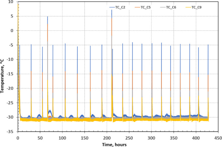
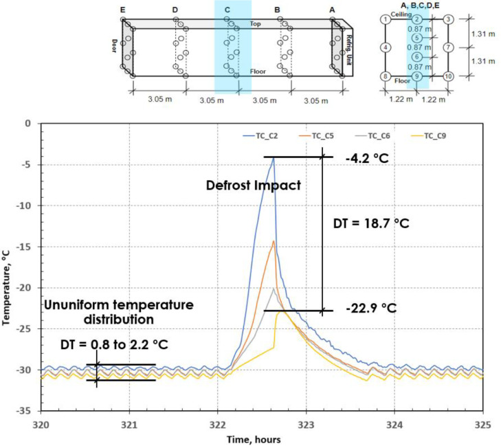
Fig. 5 shows the temperature profiles of four temperature measurements (C2, C5, C6, C9 in Fig. 3). Fig. 6 plots the temperature profile of one defrost period. In this test case, a typical defrost strategy of container refrigeration system: time-based strategy (once every 24 h), was applied. The defrost was conducted through shutting down the refrigeration system and turning on the electrical heater installed under the evaporator coil. The test results indicate the following:
-
•
In general, the refrigerated storage container maintained the set point temperature during testing except for the defrost period.
-
•
The container temperatures increased to the range of 15–25 °C in most of the defrost period. During door open events, the temperature rose above 35 °C.
-
•
Because of defrost operation, the refrigerated container air temperature control excursion lasted approximately 2 h in this test which depends on the cargo load and container insulation. During this defrost period, the air temperature rose. The defrost operation (e.g., termination temperature limits) can be adjusted to minimize the container air temperature rising.
Fig. 5.
Temperature profiles of temperature measurement close to the refrigerated storage container ceiling.
Fig. 6.
Defrost period temperature profiles of temperature measurement.
Because the air was supplied by the refrigeration system from the floor and returned to the top, the temperatures close to the unit top (C2), as shown in Fig. 6, were around 0.8–2.2 °C higher that the temperatures close to the unit floor (C9). During the defrost period, this temperature difference was around 19 °C. Other test data also indicate the air temperature inside refrigerated container unit increased with the height.
The temperature distribution of the refrigerated storage container based on the test data presents several suggestions and concerns as follows:
-
•
Placing the vaccine boxes below a certain height is recommended to take advantage of the relative lower temperature near the supply air.
-
•
A height limit can be found through simulation based on the temperature gradient.
-
•
As noted earlier, the air temperature will rise during the defrost mode of the refrigeration unit, and this increased the surrounding air temperature inside the vaccine box. The potential risk of the defrost operation on the dry-ice package temperature and vaccine temperature will be discussed in the next section.
3.2. Temperature distribution inside vaccine dry-ice box/package
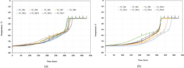
As described in previous section, a small payload box was placed inside each storage package with dry ice surround the payload box (Fig. 4). A thermocouple was placed in the center of each payload box to represent the vaccine temperature. Fig. 7 shows the temperature profiles of air inside the payload box in some dry-ice packages. The initial mass of dry ice in each storage packages are listed in Table 3 .
Fig. 7.
Vaccine payload box temperatures.
Table 3.
Initial mass of dry ice of storage packages.
| Package No. | Dry ice Mass, kg |
Package No. | Dry ice Mass, kg |
Package No. | Dry ice Mass, kg |
Package No. | Dry ice Mass, kg |
| B1 | 27.3 | B11 | 27.2 | B4 | 28.1 | B12 | 27.4 |
| B3 | 28.2 | B13 | 28.4 | B6 | 27.7 | B14 | 27.9 |
| B5 | 27.5 | B15 | 27.8 | B8 | 27.7 | B16 | 27.7 |
| B7 | 27.7 | B17 | 27.2 | B10 | 28.4 | B18 | 27.2 |
| B9 | 27.6 |
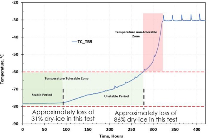
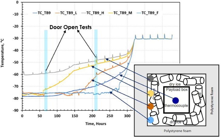
Because the temperatures of each payload box follow similar temperature profiles, a generic temperature profile of a vaccine payload box can be defined as shown in Fig. 8 . The temperature profile can be divided into two regions: a temperature-tolerable zone and a temperature non-tolerable zone. If the amount of dry ice left in the vaccine package can't maintain the payload box temperature within the required temperature range of between −80 °C and −60 °C, it is in the temperature non-tolerable zone which occurs at approximately loss of 86% dry-ice in this test. Otherwise, it is in the temperature-tolerable zone, which can be further divided into two stages: a stable period and an unstable period. In the stable period, the dry ice can keep the payload box at the dry-ice boiling point (sublimation point) temperature of −78.5 °C. When the payload box temperature starts to rise but is still within the required temperature range, it is in the unstable period of the temperature-tolerable zone. The switch time from stable period to unstable period occurs at approximately loss of 31% dry-ice in this test.
Fig. 8.
Generic temperature profile of vaccine payload box.
As shown in Fig. 9 , four thermocouples were installed inside vaccine storage package to monitor their temperature variation during dry ice sublimation.
Fig. 9.
Dry-ice package temperature profiles.
The effects of the refrigeration system defrost operation on the payload box temperature are shown in Fig. 7, Fig. 8, Fig. 9. In general, the defrost operation presents little influence on the payload box temperature at the stable stage of the temperature-tolerable zone, relatively small impact (<1 °C) on the payload box temperature at the unstable stage of the temperature-tolerable zone, and relatively large impact (>1 °C) on the payload box temperature in the temperature non-tolerable zone. Maintaining the payload box temperature within the temperature-tolerable zone is a key performance index to evaluate the ultralow-temperature refrigeration solution.
According to our observations, to maintain the vaccine temperature within the required temperature range, the vaccines should be surrounded by dry ice during the transportation and storage to avoid them being exposed to the CO2 gas released from dry-ice sublimation.
3.3. Dry-ice sublimation
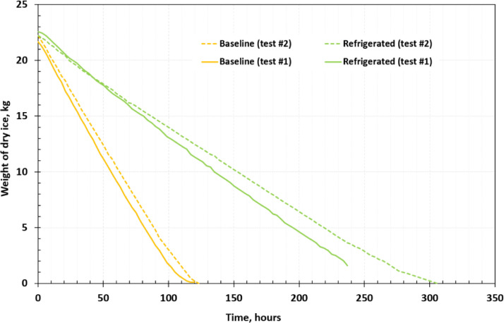
The dry-ice sublimation rate was monitored through dry-ice weight variation during the tests. The purpose of monitoring the dry-ice sublimation rate was to quantify the extended dry-ice lifetime in dry ice vaccine package stored in refrigeration containers compared with in normal indoor conditions (21.1 °C). Test data for the dry-ice weight over time are shown in Fig. 10 . Table 4 lists several dry-ice sublimation performance parameters, including sublimation rate. In both tests, the dry-ice lifetime was extended significantly when vaccine dry-ice packages were stored in refrigerated conditions vs. room ambient.
-
•
In test 1, the dry-ice lifetime was extended from 120 h to 237 h under the conditions of −30 °C refrigeration temperature and generic insulated box.
-
•
In test 2, the dry-ice lifetime was extended from 123 h to 306 h under the conditions of −35 °C refrigeration temperature and pharmaceutical box.
Fig. 10.
Dry-ice weight measurement during sublimation.
Table 4.
Dry-ice sublimation performance parameters.
| Package | Test 1 | Test 2 | ||
| Generic insulated box | Pharmaceutical box | |||
| Dry ice | Baseline | Refrigerated | Baseline | Refrigerated |
| Surrounding temperature | 21.1 °C | −30 °C | 21.1 °C | −35 °C |
| Starting weight | 21.66 kg | 22.57 g | 22.23 kg | 22.23 kg |
| Lifetime | 120 h | 237 h | 123 h | 306 h |
| Sublimation rate | 0.181 kg/h | 0.095 kg /h | 0.181 kg /h | 0.073 /h |
The test results show that the surrounding temperature of the vaccine dry-ice package significantly affects the dry-ice sublimation rate. Besides the surrounding temperature of the vaccine dry-ice box, other factors influence the dry-ice lifetime include package materials, insulation, leakage situation. Therefore, storage package design is also very critical for the vaccine storage.
3.4. CO2 concentration
According to National Institute for Occupational Safety and Health (NIOSH) (FSIS, 2020), the recommended CO2 exposure limit for 15 min is 3%. A level of 4% is designated by NIOSH as “immediately dangerous to life or health.” The NIOSH-recommended CO2 exposure limits in the workplace is 0.5%, or 5000 parts per million, for a 40 h work week.
Because of the large amount of dry ice being used in the vaccine storage, maintaining a safe level of CO2 concentration during loading/unloading is critical for this proposed vaccine distribution last-mile solution. Two ventilation strategies have been tested: fresh air ventilation (FAV) and door open strategies. The goal was to reduce the CO2 concentration build-up inside the container by introducing fresh air or opening the door.
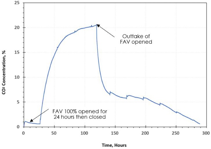
Fig. 11 shows the CO2 concentrations in the refrigerated container during the entire dry-ice sublimation. A FAV strategy was applied during the test by opening the outtake of FAV. FAV is to provide ventilation for container. The air exchanger depends on static pressure differential, which will vary depending on the container and how the container is loaded. A vent position sensor is installed to determine the position of the fresh air vent (upper or lower) and sends data to the controller display. The test results indicate that the FAV strategy is impractical for keeping the CO2 concentration at a safe level for vaccine package loading/unloading. FAV took around 22 h to drop the CO2 concentration from 20.6% to 6.4%; further reducing the CO2 concentration to 0.6% can take around 6 days (147 h), which makes the strategy impractical.
Fig. 11.
Evaluation test of FAV strategy.
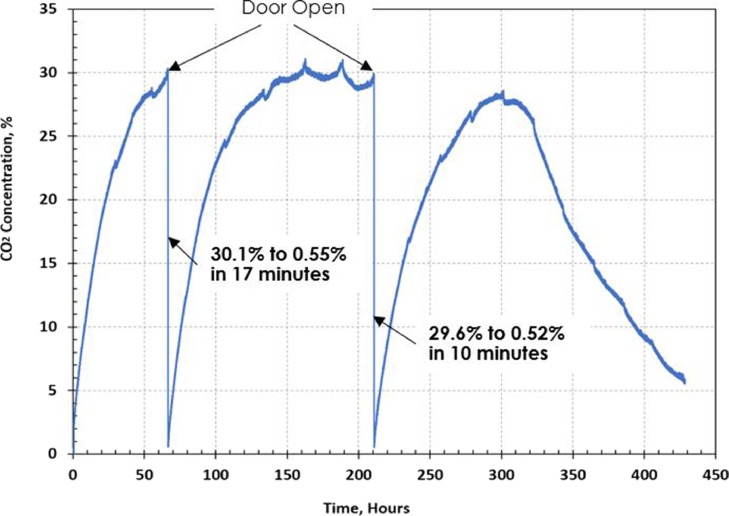
The door open strategy, as shown in Fig. 12 , is a simple and effective solution to manage the CO2 concentration within safe levels. The test results show that opening one of the rear doors (there are two rear doors) can reduce the CO2 concentration close to a safe level (5%) within 20 min.
Fig. 12.
Evaluation test of door open strategy.
3.5. Modeling and simulation
In addition to the experimental approach, modeling and simulation, for example computational fluid dynamic (CFD) modeling, has been also used to address the challenges faced by the proposed vaccine distribution solution: refrigeration storage container with vaccine dry-ice package. The modeling and simulation can not only provide a visualization of the temperature distribution in the container, but also offer an optimal distribution of the boxes with an economic cost. The modeling results can provide guidance of experimental setups to save both time and cost.
A 3D CFD model of a refrigerated container was developed using a commercial software, ANSYS/FLUENT (version 17.2) (ANSYS, 2017) . The model was used to investigate the airflow, temperature distribution, and CO2 distribution in the container
3.6. Mathematic model
The refrigerated container model used in this study has dimension of L = 11.65 m, H = 2.56 m, and W = 2.28 m. A Cartesian coordinates system was employed in which x, y, and z are the directions for width, height, and length of the container, respectively. A refrigeration unit was located at the back of the container with the return air grille located near the ceiling of the container. Insulated sandwich panels formed the ceiling and walls of the container. The interior surface of the wall and ceiling panels consisted of a stainless steel sheet, and the exterior side was covered with an aluminum sheet. The insulating material between the steel and aluminum sheets is polyurethane (PUR). The PUR panel was 136 mm thick for the ceiling and 66 mm thick for the walls. The stainless steel and aluminum sheets were both 2 mm thick. The air inlets (supply air) were located at the floor of the container, where a series of T-shaped floor beams were used as diffusers to disperse the airflow. Twenty boxes filled with dry ice, with L box = 0.54 m, H box = 0.5 m, and W box = 0.5 m, were deployed on the floor of the container.
Because CO2 leaks from the vaccine boxes to the container, in the present work, two-phase flow, air and CO2, was modeled. A mixture model was employed to describe the multi-phase flow and heat transfer. The governing equations of the mixture model include continuity, momentum, and energy equations.
| (1) |
| (2) |
| (3) |
where, is the mass averaged (mixture) velocity and is the mixture density, p is the pressure and μ t is the turbulence dynamic viscosity. μ m is the viscosity of the mixture, λ eff is the effective conductivity and h l is the enthalpy for phase l. The detail calculation of these variables is elaborated by Sun et al. (2021).
Air and CO2 were treated as incompressible ideal gases in this model. The flow was turbulent in all conditions evaluated, so a standard k-ε model was adopted in the model. Therefore, the turbulence dynamic viscosity can be written as
| (4) |
The k-ε model can be found in the reference (ANSYS, 2017).
3.7. Simulation results
The validated CFD model was used to simulate a refrigerated container exposed to a sunny day from morning (07:00) to evening (16:00). Several assumptions have been made for this simulation as following,
-
•
The temperature changes of three external surfaces of a refrigerated container caused by solar radiation referred to existing studies at Hakata Port, Japan (Shinoda, 2016; Budiyanto et al., 2017) .
-
•
Because of the lack of temperature data on the container door surfaces and the relatively small surface area of the doors compared with the other surfaces, the door surfaces were assumed to be perfectly insulated in the present case study.
-
•
The simulation started at 07:00, when the air temperature in the container was −33 °C. Initially, the CO2 concentration was 409.8 ppm, which is the average atmospheric CO2 concentration (Lindsey, 2020).
-
•
After 07:00, CO2 started to leak from the vaccine packages to the container at a rate of 0.0832 kg/h per package based on the experimental measurement.
-
•
The supply air was blown from the T-shaped floor to the container starting at 07:00 at a rate of 0.38 m3/s (800 CFM) and a temperature of −37.3 °C.
-
•
In this simulation, other operations, such as defrost and opening/closing of the door, were ignored to simplify the model.
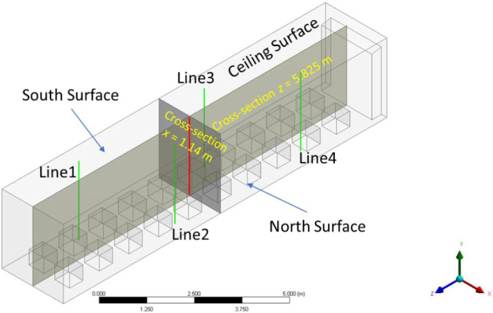
To investigate the temperature distribution in the container and the insulating panels, five vertical lines were defined, which are line 1 to line 4 (green lines in Fig. 13 ) and the center line (red line). The center line is the cross-line of the planes x = 1.14 m and z = 5.825 m, located in the center of the container.
Fig. 13.
Surface directions and two cross-sections located at the middle of the refrigerated container.
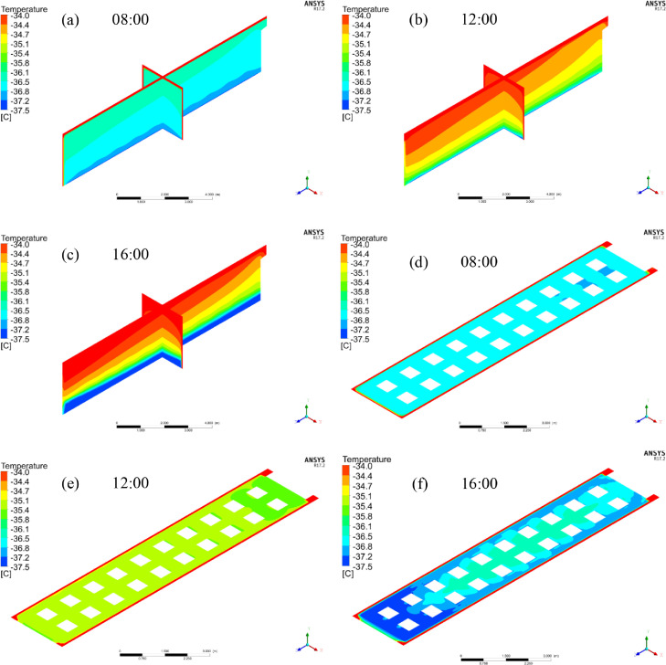
The temperature distribution at that moment is confirmed by Fig. 14 a, which depicts the temperature distribution on the two cross-sections at 08:00. Subsequently, because of the solar radiation and higher ambient temperature, the container temperature started to rise, so the container temperature at 12:00 was much higher than at 08:00. Also, a constant temperature region below y = 0.25 m existed only at 16:00, whereas temperature kept increasing after leaving the T-shaped floor at 08:00 and 12:00 because the circulating flows had not been developed at 08:00 and 12:00. Therefore, at 08:00 and 12:00, supply air flowed directly upward and could not generate a constant temperature region. To visualize the temperature distribution near the vaccine packages, Fig. 14d–f show the temperature profiles at the cross-section y = 0.4 m at 08:00, 12:00, and 16:00, respectively. These profiles indicate that at 08:00, near all the packages, the temperature was lower than −36 °C. Because of the temperature of the external surfaces, the temperature increased to about −35 °C at 12:00. At 16:00, the temperature near the packages was even lower than at 12:00 because of the circulating flows.
Fig. 14.
Temperature profiles on the cross-sections, including x = 1.14 and z = 5.825 (a, b, c), and y = 0.4 m (d, e, f) at 08:00, 12:00, and 16:00.
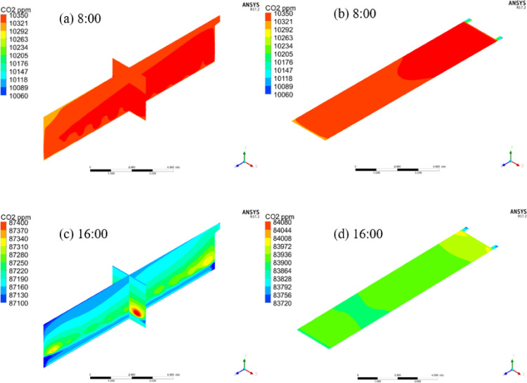
In addition to temperature distributions within the refrigerated container, the CO2 concentration was also studied because of the use of dry ice in the vaccine packages. Because of CO2 accumulation, the CO2 concentration kept increasing from 08:00 to 16:00, from about 10,000 to 85,000 ppm. Because of the lack of circulating flows, at 08:00, the CO2 concentration was increasing from the door to the refrigeration unit (Fig. 15 a and b) following the airflow direction. Previous study shows that the CO2 concentration above 1000 ppm could potentially be harmful to human health [9], so even at 08:00, the container was not safe to human health. Therefore, extra fresh air ventilation is essential to ensure the safety of people entering the container.
Fig. 15.
CO2 profiles on the cross-sections, including x = 1.14 and z = 5.825 (a, b), and y = 1.7 m (c, d) at 08:00 and 16:00 inside the container.
Some key conclusions from this study are as follows:
-
•
At 16:00, in the container, a circulating flow pattern was observed. Such a pattern did not exist at 08:00.
-
•
The circulating flow acted as a limiting factor to resist heat transfer in the container when y < 0.25 m. Therefore, a constant temperature region existed when y < 0.25 m at 16:00. As a result, the temperature around the box at 16:00 was lower than at 12:00. However, at 08:00 and 12:00, such a constant temperature region did not exist in the container.
-
•
The PUR panels played a critical role in keeping the temperature in the container low even on a summer day.
-
•
The circulating flow also acted as a cap to resist CO2 spreading in the container, leading to a low CO2 concentration region when y < 0.25 m.
-
•
The CO2 concentration was about 85,000 ppm in the container at 16:00 because of the accumulation of CO2. Even at 08:00, the CO2 concentration was still above 10,000 ppm, which is much higher than what is safe for human health. Therefore, extra fresh air ventilation is essential to ensure the safety of people entering the container for off-loading the product.
4. Conclusion
The purpose of this study was to mitigate the last-mile challenge faced by COVID-19 vaccine distribution, especially for rural or suburban areas, where local towns, pharmacy chains, and hospitals may not have the infrastructure required to store the vaccine at the required temperature. This study proposes an effective, secure, and safe ultralow-temperature refrigeration solution that uses commercially available refrigeration container units that are operated in the global cold-food chain and can be modified quickly to support the vaccine distribution supply chain according to the more demanding requirements of vaccine storage.
To evaluate the technical merits and potential risk of this proposed solution, tests and computational fluid dynamics simulation studies were conducted to evaluate temperature distributions of refrigeration storage containers and vaccine packages, as well as the dry-ice sublimation process. According to the test and simulation results, several conclusions and observation are summarized as follows.
4.1. Temperature distribution of refrigerated storage container
For the tested refrigeration storage container with supply air at the floor and return air at the top, refrigeration storage container temperature gradient analysis though testing and simulations suggest placing the vaccine boxes at the floor to minimize the refrigeration storage container air temperature variation, especially during the defrost period, and maximize the dry-ice lifetime.
The refrigeration storage container temperature increased significantly during the defrost operation.
4.2. Temperature distribution inside vaccine dry-ice box/package
Along with dry-ice sublimation, temperatures inside the vaccine package were not uniformly distributed. The dry-ice section maintained its sublimation temperature of −78.5 °C, whereas the temperature of the CO2 gas section rose because of the heat transfer or leakage with air outside the vaccine box.
A generic temperature profile of vaccine payload box was defined to include two regions: temperature tolerable zone and temperature non-tolerable zone. If the amount of dry ice left in the vaccine package cannot maintain the payload box temperature within the required temperature range, it is in the temperature non-tolerable zone. Otherwise, it is in the temperature-tolerable zone, which can be further divided into two stages: a stable period and an unstable period. In the stable period, the dry ice can keep the payload box at the dry-ice boiling point (sublimation point) temperature of −78.5 °C. When the payload box temperature starts to rise but is still within the required temperature range, it is in the unstable period of the temperature-tolerable zone.
In general, the defrost operation presents little influence on the payload box temperature at the stable stage of the temperature tolerable zone, relatively small impact (<1 °C) on the payload box temperature at the unstable stage of the temperature tolerable zone, and relatively large impact (>1 °C) on the payload box temperature in the temperature non-tolerable zone. Therefore, ensuring enough dry ice surrounds the vaccine inside the dry-ice package is critical to maintain the vaccine temperature within the required temperature range.
4.3. Dry-ice sublimation
The surrounding temperature of vaccine packages was shown to significantly affect the dry-ice sublimation rate. Under the lab test setup, compared with typical 21.1 °C ambient storage, using a −35 °C storage temperature extended the dry-ice lifetime by approximately 2.49 times. Other factors influencing dry-ice lifetime include vaccine box design, insulation, leakage rate, and dry-ice fill density.
4.4. CO2 concentration
The existing FAV strategy is not a practical solution to maintain a safe CO2 concentration level for vaccine package loading/unloading procedures because of the long time to reduce the CO2 concentration to near the safe level of 0.5%.
We recommend opening the rear door for at least 30 min before accessing the refrigerated container to load/unload vaccine package. In addition, we recommend having portable CO2 monitoring to ensure that the CO2 concentration is below the safe limit before accessing the refrigeration storage container.
Declaration of Competing Interest
The authors declare that they have no known competing financial interests or personal relationships that could have appeared to influence the work reported in this paper.
Acknowledgements
Funding for this research was provided by the US Department of Energy, Office of Energy Efficiency and Renewable Energy. The authors would like to thank Erika Gupta and Samuel Petty, Program Manager of Building Technologies Office, for their support of this work. The authors would like to thank the support from the Oak Ridge National Laboratory Operations and Facilities team (Gerald Barth, Margret Smith, Brandy Milun). The authors would like to thank Doug Auyer, David Brisson from Carrier Global Corporation to provide some test data. The authors would like to thank leadership team's support from both Oak Ridge National Laboratory Energy Science and Technology Directorate (Xin Sun, Lonnie Love, Marti Head, Ron Ott, Richard Raines, Robert Wagner, Yarom Polsky) and Carrier Global Corporation (Bruce Hoopes, Yu Chen, Stella Oggianu, Nader Awwad, Chris Repice, James Fan).
Footnotes
This manuscript has been authored in part by UT-Battelle, LLC, under contract DE-AC05-00OR22725 with the US Department of Energy (DOE). The US government retains and the publisher, by accepting the article for publication, acknowledges that the US government retains a nonexclusive, paid-up, irrevocable, worldwide license to publish or reproduce the published form of this manuscript, or allow others to do so, for US government purposes. DOE will provide public access to these results of federally sponsored research in accordance with the DOE Public Access Plan (http://energy.gov/downloads/doe-public-access-plan).
Reference
- ANSYS . 2017. ANSYS FLUENT 17.2 Theory Guide. [Google Scholar]
- Budiyanto M.A., Shinoda T., Nasruddin . Institute of Physics Publishing; 2017. Study on the CFD Simulation of Refrigerated container, in: IOP Conf. Ser. Mater. Sci. Eng. [DOI] [Google Scholar]
- FSIS Environmental, Safety and Health Group . 2020. Carbon Dioxide Health Hazard Informaiton Sheet, ESHG-Health-02.00. Carbon Dioxide (usda.gov. [Google Scholar]
- Heilweil R. How quick can US distribute a Covid-19 vaccine? Here are the four biggest logistical challenges. Recode. 2020 https://www.vox.com/recode/22151473/vaccine-covid-19-pfizer-glass-syringes-needles-freezers Dec. 7. [Google Scholar]
- Lindsey, R., Climate change: atmospheric carbon dioxide, Climate.gov, Aug. 14, 2020, https://www.climate.gov/news-features/understanding-climate/climate-change-atmospheric-carbon-dioxide.
- Owens C. 2020. Vaccinating Rural America Won't Be Easy.https://www.axios.com/coronavirus-vaccine-rural-america-08f26b2c-b4a2-4a3c-b794-25fd394a629a.html AxiosNov. 30. [Google Scholar]
- Sari S.K., Pratami N.W. Cooling load calculation of cold storage container for vegetables case study C Campus-UISI, Ngipik, in: 2018. Int. Conf. Inf. Commun. Technol. ICOIACT. 2018;2018:820–826. doi: 10.1109/ICOIACT.2018.8350726. [DOI] [Google Scholar]
- Shinoda T., Budiyanto M.A. Energy saving effect of roof shade for reefer container in marine container terminal. J. Jpn. Inst. Navig. 2016;134:103–113. doi: 10.9749/jin.134.103. [DOI] [Google Scholar]
- Sun, J., Zhang, M., Fricke, B., Nawaz, K., Gluesenkamp, K., Shen, B., Munk, J., 2021, COVID-19 vaccine distribution solution to the last-mile challenge: cryogenic refrigeration to facilitate the maintenance of ultralow temperature, ORNL/TM-2021/1903.


