Abstract
Social distancing is a key factor for health during the COVID-19 pandemic. In many indoor spaces, such as elevators, it is difficult to maintain social distancing. This investigation used computational-fluid-dynamics (CFD) to study airborne particle exposure in riding an elevator in a typical building with 35 floors. The elevator traveled from the ground floor to the 35th floor with two stops on floor 10 and floor 20, comprising 114 s. The CFD simulated the dispersion of the aerosolized particles exhaled by an index person while breathing in both lobby and elevator areas. The study calculated the accumulated dose of susceptible riders riding in elevators with the index person under different conditions including different ventilation rates, air supply methods, and elevator cab geometries. This investigation also studied a case with a single cough from the index person as the person entered the elevator. The results show that, due to the short duration of the average elevator ride, the number of particles inhaled by a susceptible rider was low. For the reference case with a 72 ACH (air changes per hour) ventilation rate, the highest accumulated particle dose by a susceptible passenger close to the index person was only 1.59. The cough would cause other riders to inhale approximately 8 orders of magnitude higher particle mass than from continuous breathing by the index person for the whole duration of the ride.
Keywords: Airborne particles, COVID-19, Enclosed spaces, CFD, Dynamic mesh
1. Introduction
The spread of COVID-19 across the globe has brought a catastrophe to societies. Transmission of COVID-19 during riding elevators has been a significant concern as many people take elevators almost every day. In addition, the elevator is generally small and potential for high occupant density, which creates ideal conditions for COVID-19 transmission. Cases of possible COVID-19 transmissions in enclosed spaces have been reported by the news media, such as in elevators [[1], [2], [3]], airplanes [[4], [5], [6]], restaurants [7], and other similar rooms [8]. The transmission modes of COVID-19 are mainly by contact and droplet transmission, airborne transmission, and fomite transmission [9]. Although any of these three routes of transmission can occur in an elevator, viral transmission via small airborne micro-droplets and particles has received considerable attention [[10], [11], [12]]. This study also focused on the relative exposure for airborne particle transmission due to its complex transmission mechanism [[13], [14], [15]].
Particles with germs are mixed in the air to form aerosols that follow the airflow and cause infection when inhaled [[16], [17], [18]]. The aerosols released by infected individuals through sneezing, coughing, talking, and breathing could accumulate in the air over time, increasing in concentration, if the elevator is not well ventilated. Smaller virus-containing particles can remain suspended in the air over long distances and time periods [19]. Nishiura et al., 2020 [20] found that transmission of COVID-19 in a confined space was 18.7 times greater compared to an open-air environment. In enclosed spaces, the airflow pattern induced by the ventilation systems has large influence on the airborne particle transmission [[21], [22], [23]]. Therefore, the ventilation system of the elevator is important for efficiently diluting or removing the aerosol concentration [24]. In addition, Mazumdar et al. [25] found that the wake generated by a walking person can carry SARS virus as far as 7 m. Blocken [26] recently studied COVID-19 transmission for people running in an outdoor environment, and found that particles generated can be dispersed much farther due to people's movements. Many investigations [[27], [28], [29], [30]] have found that the aerodynamic effects of human movement can significantly influence the airflow motion and contaminants transmission in enclosed environments. Therefore, for airborne transmissions of COVID-19 when riding elevators, the dynamic behavior of the people should be considered.
Very few studies are available from literature evaluating the airborne particle exposure for riding elevators, and those studies may not have been sufficiently thorough. For example, Lim et al. [31]] explored the airborne transmissions in a high-rise hospital building due to the stack effect through he elevator shaft. However, they did not pay much attention to the indoor aerosol transmission in the elevator cab. Shao et al. [32] investigated the risk of airborne transmission of COVID-19 under different practical settings using computational-fluid-dynamics (CFD) simulation, including an elevator, a small classroom, and a supermarket. They found that highly non-uniform spatial risk distribution in the elevator and ventilation system played a major role. However, this investigation studied only steady airborne transmission inside an elevator cab that was not representative of a typical elevator ride. Dbauk and Drikakis [33] explored the airborne virus transmission in elevators and confined spaces. They found that the position of the inlets and outlets significantly influences the flow circulation and droplet dispersion. However, they mainly focused on the fluid dynamics of respiratory droplets in a confined elevator with only one person standing still in the cab, which did not consider the dynamic process of taking the elevator.
Based on the current understanding and the state-of-the-art in studying airborne particle transmission in enclosed spaces, the objectives of this investigation were (1) to evaluate dynamic airborne particle exposure when riding an elevator, and (2) to study different elevator design parameters that could have a major impact on the airborne particle exposure.
2. Research method
This section discusses a typical elevator ride used in this investigation, the case design, and the computer methods used to evaluate accumulated particle dose by susceptible riders with an index person.
2.1. Typical elevator ride
To consider the whole process when taking an elevator, we assumed an elevator ride scenario in a representative building with 35 floors with a 4 m height of each floor. This is a general commercial building height in China. The building had four elevators side by side. Six people waited in the lobby of the ground floor, and one of them was an index person as shown by the red color in Fig. 1 . When the elevator arrived and the elevator door opened, the six people walked successively into the elevator cab. After the door was closed, the elevator cab moved from floor 1 to floor 10. Here, the elevator door opened again, and two riders disembarked. Then the remaining four riders continued their journey from floor 10 to floor 20. Again, another two riders moved out from the cab on floor 20. The remaining two riders, including the index person, continued the trip from floor 20 to floor 35. Finally, these two riders left the cab on floor 35. Note that the generalization of the typical elevator ride is not made according to particular situations but our assumption. More scenarios such as different relative positions (face to face or with an orientation angle between two people), different person densities, different traffic flow patterns, etc. should be considered in the future investigation.
Fig. 1.
The schematic diagram of the whole process when taking the elevator.
Fig. 2(a) shows the duration of the elevator ride for different stages. The longest ride from floor 1 to floor 35 was 114.1 s. The floor areas or flow domains studied varied during the ride. The lobby on floor 1 was larger than that of the other floors. Fig. 2(b) illustrates in more detail the ground floor lobby with four elevator doors. The elevator lobby was connected to the main building lobby and other spaces in the building. Thus, the two light-yellow color surfaces were not walls but the flow domain boundaries with zero relative pressure (Outlet). The size of the elevator lobby was 11.5 m long, 5.0 m wide, and 4.0 m high. The elevator cab represented a typical model with a 1600 kg capacity, at 2.0 m long, 1.65 m wide, and 2.5 m high. The diffusers which supply the air to the lobby were installed in the ceiling of the lobby. The size of the diffusers is 0.4 × 0.4 × 0.03 m.
Fig. 2.
(a) the duration and flow domains for different stages of the elevator ride (total duration was 114.1 s), (b) the flow domain considered on the ground floor (floor 1).
2.2. Case design
Table 1 summarizes our case design parameters used for this investigation. Case 1 was the reference case. The airflow rate was 0.165 m3/s, which corresponds to 72 ACH. No intervention methods were used. Previous investigation [34] found that viral respiratory infected individuals shed virus into the environment by coughing or sneezing or even during quiet breathing. Since the breathing from the index person was a continuous process and had low uncertainty, we selected breathing as the particle dose for further evaluation of airborne particle exposure in riding the elevator. In case 2, we only changed the particle source to coughing for the index person, and other parameters remained the same as case 1. Case 2 was designed for studying the impact of particle sources from the index person upon dose inhaled by susceptible passengers. Cases 1, 3, 4 and 5 were designed for studying different ventilation rates due to mechanical ventilation and infiltration. In case 6, the air supply direction was changed from blowing in to blowing out, but other parameters were the same as those in Case 1. Case 6 was designed for studying different air supply direction. In case 7, we used a deeper cab with a smaller floor area to explore the impact of elevator geometry on the dose level of susceptible passengers. The above analysis can provide a quantitative evaluation of the accumulated particle dose (by count or mass) by a susceptible passenger riding the elevator.
Table 1.
Key parameters for different cases studied.
| Case | Spaces | Airflow direction | Flow rate (m3/s) | Ventilation rate (ACH) | Dimension (m3) | Inter-vention | Particle source |
|---|---|---|---|---|---|---|---|
| 1 | Elevator | In | 0.165 | 72 | 2.00 × 1.65 × 2.50 | None | Breathing |
| 2 | Elevator | In | 0.165 | 72 | 2.00 × 1.65 × 2.50 | None | Coughing |
| 3 | Elevator | In | 0.071 | 31 | 2.00 × 1.65 × 2.50 | None | Breathing |
| 4 | Elevator | In | 0.026 | 11 | 2.00 × 1.65 × 2.50 | None | Breathing |
| 5 | Elevator | Infiltration | 0.017 | 7 | 2.00 × 1.65 × 2.50 | None | Breathing |
| 6 | Elevator | Out | 0.165 | 72 | 2.00 × 1.65 × 2.50 | None | Breathing |
| 7a | Elevator | In | 0.026 | 23.6 | 1.10 × 1.80 × 2.00 | None | Breathing |
The cab with 2.00 × 1.65 × 2.50 m3 had 1600 kg capacity and the cab with 1.10 × 1.80 × 2.00 m3 had 1000 kg capacity.
2.3. Numerical procedure
This investigation further used the RNG k-ε model [35] from a CFD program, ANSYS Fluent version 2019, to simulate COVID-19 virus transmission when taking the elevator. The index person with COVID-19 is shown in red color in Fig. 2(a) and in green color in Fig. 2(b). Previous investigation found that [36] the manikin geometry has little influence on the airflow around the person. Comparison of the results between the heated rectangular column and human subject indicated a satisfactory agreement of the overall flow pattern. To simplify the simulation, we used a rectangular column to represent a person as shown in those figures. Our preliminary simulation was for a breathing case in which the index person exhaled particles with an average of 0.4 μm in diameter. The total number of particles exhaled per breath was 525 [37] from the nose of the index person. The injection direction was (0.5 m/s in the horizontal direction, 0 m/s to the side, −0.866 m/s downwards), representing normal breathing from the nose of the person with an angle of 30° downwards. The breathing flow rate from the nose was set according to the measured data from Gupta et al. [37] implemented by a user-defined function (UDF) in ANSYS Fluent.
The simulation used unsteady-state Reynolds-averaged Navier-Stokes (RANS) equations with the RNG k-ϵ turbulence model to solve the airflow and temperature fields in the cab and lobby. The governing transport equations were solved by means of the finite volume method. The numerical method used the SIMPLE (semi-implicit method for pressure-linked equations) algorithm for coupling pressure and velocity equations, and the second-order discretization schemes for the convection and viscous terms of the governing equations. The Boussinesq model was used to consider the temperature difference in the domain. The temperature boundaries were listed in Table 2 . The results were considered converged when the residuals for all the independent parameters reached 10−4.
Table 2.
Boundary conditions for sub-case 2 in case 1 (reference case).
| Boundary surface | Velocity | Temperature (oC) | Particle |
|---|---|---|---|
| Human body | No slip | 31 [36,44] | Trap |
| Elevator walls | No slip | Adiabatic | Trap |
| Lobby walls | No slip | Adiabatic | Trap |
| Inlets (elevator) | 0.47 m/s (Normal to the boundary) | 22 | Reflect |
| Outlets (elevator) | Outflow | – | Escape |
| Diffuser (Lobby) | 2.07 m/s (Angle of 15° from the ceiling) | 22 | Reflect |
| Outlets (Lobby) | Outflow | – | Escape |
| Mouth and nose of the index person | UDF | 33 | Reflecta |
Note that the particles were injected when the velocity was positive. When the velocity was negative, no particle was released from the mouth.
This investigation used the Lagrangian method to track individual particle motion being breathing out. The Lagrangian method tracked particle phase separately through the flow domain by solving the force balance equations of particle movement. According to Chen and Zhao [38], the evaporation effect of droplets with sizes considered in this study can be neglected because of the high evaporation rate for small droplets. Previous investigation [39] found that the pressure gradient force and the virtual mass force could be neglected due to the small ratio of air density to particle density. The Saffman's force and Brownian force only have a substantial effect on sub-micron particles [40]. Considering the small amount of the aerosol particles in indoor air, the collision in particles can be neglected [41,42]. Therefore, this investigation did not consider them in the particle movement equation. The Lagrangian method determines the particle model in accordance with Newton's law:
| (1) |
where the first and second terms on the right-hand side represent the drag force and gravity term, respectively, air viscosity, d p particle diameter, particle velocity vector, air velocity vector, gravitational acceleration vector, particle density, air density, and C c the Cunningham correction factor. The Cunningham correction factor can be expressed as:
| (2) |
where is the mean free path of air molecules.
Particle turbulent dispersion, which is associated with instantaneous flow fluctuations, is one of the main mechanisms of the spread of particles. This study used the discrete random walk (DRW) model [43] to calculate the particle turbulent dispersion. This study assumed no particle resuspension, so particles were considered trapped once they reached a wall surface. Similarly, when a particle reached an outlet, the calculation of that particle's trajectory ended.
The CFD model used different computational domains for the 114 s elevator ride. Since the whole elevator ascension process was exceedingly difficult to simulate at once, this study separated the whole process into eight sub-cases as shown in Fig. 3 . Fig. 3 shows the size of the flow domain for the eight sub-cases of the ride. In sub-case 1, six riders stood still in the lobby waiting for the elevator for 30 s. A steady mesh was used to simulate the airflow and particle transmission in the lobby. In sub-case 2, we first employed a UDF to transfer all the flow and particle data from the lobby to sub-case 2 as the initial condition, including the distributions of air velocity, temperature, pressure, turbulent kinetic energy, particle distributions, etc. Fig. 4 shows the velocity distributions transferred from one case to another with different geometries and mesh types using the UDF. We can find that the data can be successfully transferred without too much differences. Then, the six riders moved successively into the elevator cab with a walking velocity of 0.5 m/s. The total walking time was 13 s. A UDF describing rigid body motion was used to realize the rider movement along with re-meshing methods in ANSYS Fluent. In sub-case 3, the simulated results from sub-case 2 were first transferred as the initial conditions for sub-case 3. Then, the riders stood in the elevator for 16 s. We did not simulate the cab movement from floor 1 to floor 10 but only the particle dispersion process. Therefore, a steady mesh was used. Since there was no direct connection between the cab and the lobby, the computational domain contained only the cab area. In sub-case 4, the simulated results from sub-case 3 were first transferred as the initial conditions for sub-case 4. Then, the two riders near the cab door moved successively out of the cab to the lobby. A UDF along with re-meshing methods was used in ANSYS Fluent to describe the movement of the two riders. The simulation for sub-case 5 was similar to that for sub-case 3; sub-case 6 to sub-case 4; sub-case 7 to sub-case 5; and sub-case 8 to sub-case 6.
Fig. 3.
Computational geometry of the eight sub-cases: (a) sub-case 1, (b) sub-case 2, (c) sub-case 3, (d) sub-case 4, (e) sub-case 5, (f) sub-case 6, (g) sub-case 7, (h) sub-case 8.
Fig. 4.
Data transfer between different cases with different geometries and mesh types.
This investigation used Gambit software (version 2.4.6) [44] to generate a discrete grid for discretizing the governing transport equations and ANSYS Fluent to perform the CFD simulations. Because of the complexity of the geometrical model, this study used the tetrahedral grid, which can be adapted to various geometric structures. This investigation used the smoothing and dynamic re-meshing method in ANSYS Fluent to realize human walking. We used Spring/Laplace/Boundary Layer in smoothing method which specifies that the smoothing method is spring-based, or appropriate for the Laplacian smoothing method (for 2.5D re-meshing) or the boundary layer smoothing method. In the re-meshing method, re-meshing sizing options were based on local cells and local faces. The sizing function was also used to ensure better transitions of the grid size. A UDF describing rigid body motion was used to realize the rider movement along with re-meshing. The grid for the eight sub-cases was 3.65 million, 3.62 million, 0.76 million, 3.17 million, 0.67 million, 2.95 million, 0.48 million, and 2.87 million, respectively.
2.4. Boundary conditions
Table 2 summarizes the boundary conditions for sub-case 2 in case 1 (reference case). For the human body, a constant surface temperature of 31 °C [37,45] was adopted. This is generally the temperature of the human body after wearing clothes. The human body was modeled as a rectangular column with dimensions of 0.4 m × 0.2 m × 1.68 m. All the walls of the elevator and lobby were treated as adiabatic. The conditioned air with a temperature of 22 °C was supplied from the ceiling of the elevator. The velocity was 0.47 m/s, and the direction was normal to the surface. The inlet area of the elevator is 0.351 m2. The corresponding airflow rate is 0.165 m3/s. We set two diffusers in the lobby to supply conditioned air with 22 °C. The total airflow rate from the diffusers was 0.192 m3/s, which corresponded to 3 ACH. The lobby was connected to the main lobby and other spaces in the office building. The breathing flow rate from the mouth of the index person was set according to the measured data from Gupta et al. [[37], [45]] through a UDF.
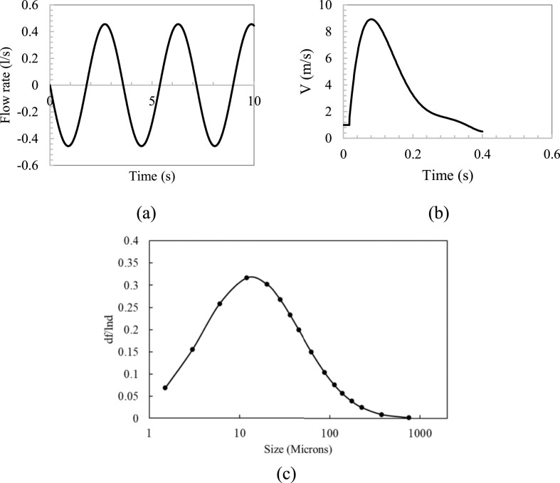
This study investigated particle sources generated by an index person through breathing and coughing. For breathing, the particle size used for the numerical simulation was averaged with 0.4 μm in diameter and the count is 525 particles per breathing cycle from Gupta et al. [[37], [45]]. Each breathing cycle lasted 4 s. Fig. 5 (a) shows the flow boundary conditions for breathing through the nose. For coughing, this study used 16 different particle sizes and counts through Chao et al. study [46], as shown in Fig. 5(c). The total particle count per cough was 1951. The particles were injected into the flow for the whole stage for 0.4 s. Fig. 5(b) depicts the coughing velocity generated from the index person.
Fig. 5.
Boundary conditions for breathing and coughing: (a) Flow generated over time for index person [36], (b) Coughing velocity generated over time for index person [[37], [45]], and (c) Particle size distribution for coughing from Chao et al. [46] study.
2.5. Calculation of accumulated particle dose
To estimate the accumulated particle dose inhaled by each susceptible person, this investigation developed a UDF to calculate accumulated particle counts through Eq (3). or accumulated particle mass by Eq (5). in the breathing zone of each person, which was outputs of the CFD simulation. The breathing zone was a spherical space centered on the nose of each person with a radius of 0.2 m [47,48]. The particles in the breathing zone were calculated in each time step (0.01 s). Then the accumulated particles can be summed for the whole ride of each person. Note that this investigation did not accurately simulate the process of particles being breathed into the lung of the susceptible person. Instead, we assumed if the particles were suspended in the breathing zone of the susceptible person, the particles would be breathed in by the person. Therefore, even though the particle number in the breathing zone is always the same, the accumulated dose will increase over time. In addition, the uneven distribution of particles in the breathing zone does not influence the results since the breathing zone was taken as a whole zone. Besides, since the accumulated dose was related to the exposure time, it is more rational to compare the exposure risk under the same time.
| (3) |
With
| (4) |
And
| (5) |
With
| (6) |
where N j and M j are the accumulated particle count and mass inhaled by person j, respectively; C j,t and ρ j,t the numerical particle concentration and the average particle density in the passenger's breathing zone at time t, respectively; p the passenger's breathing flow rate (0.00053 m3/s) [49]; num t the total particle count in the breathing zone; and mass k,t the mass of the particle k in the breathing zone at time t.
3. Results
3.1. CFD validation
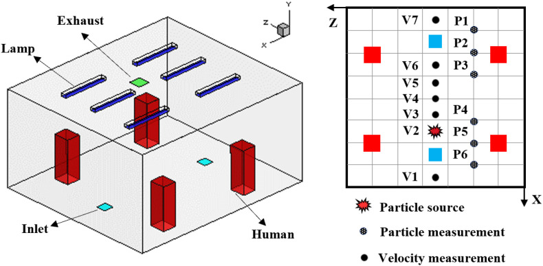
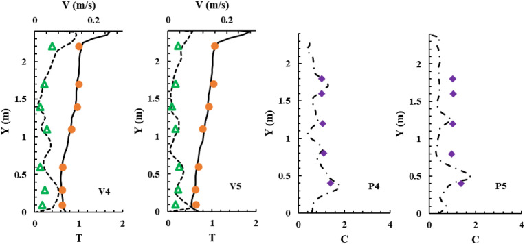
To validate the performance of CFD models for calculating particle transmission, this investigation first validated our CFD simulations by comparing our simulated results with experimental data from an enclosed room with displacement ventilation [50] as shown in Fig. 6 . Fig. 7 compares the simulated and measured velocity, temperature, and particle concentration distributions. The results of the Lagrangian calculation in this figure were based on sample size (i.e., the number of trajectories) of 1.2 million. The results are in reasonable agreement with the experimental data thus validating the simulation technique presented in this paper.
Fig. 6.
A sketch of the environmental chamber configuration and experimental arrangements used by Zhang and Chen [50].
Fig. 7.
Comparison of simulated and measured data at different measuring locations. Note: dots – measured dimensionless temperature (T - Tsupply)/(Texhaust- Tsupply); triangles - measured velocity; diamonds - measured dimensionless particle concentration (C - Csupply)/(Cexhaust- Csupply); solid lines - simulated dimensionless temperature; dash lines - simulated velocity; dash-dot lines - simulated dimensionless particle concentration.
3.2. Reference case (case 1)
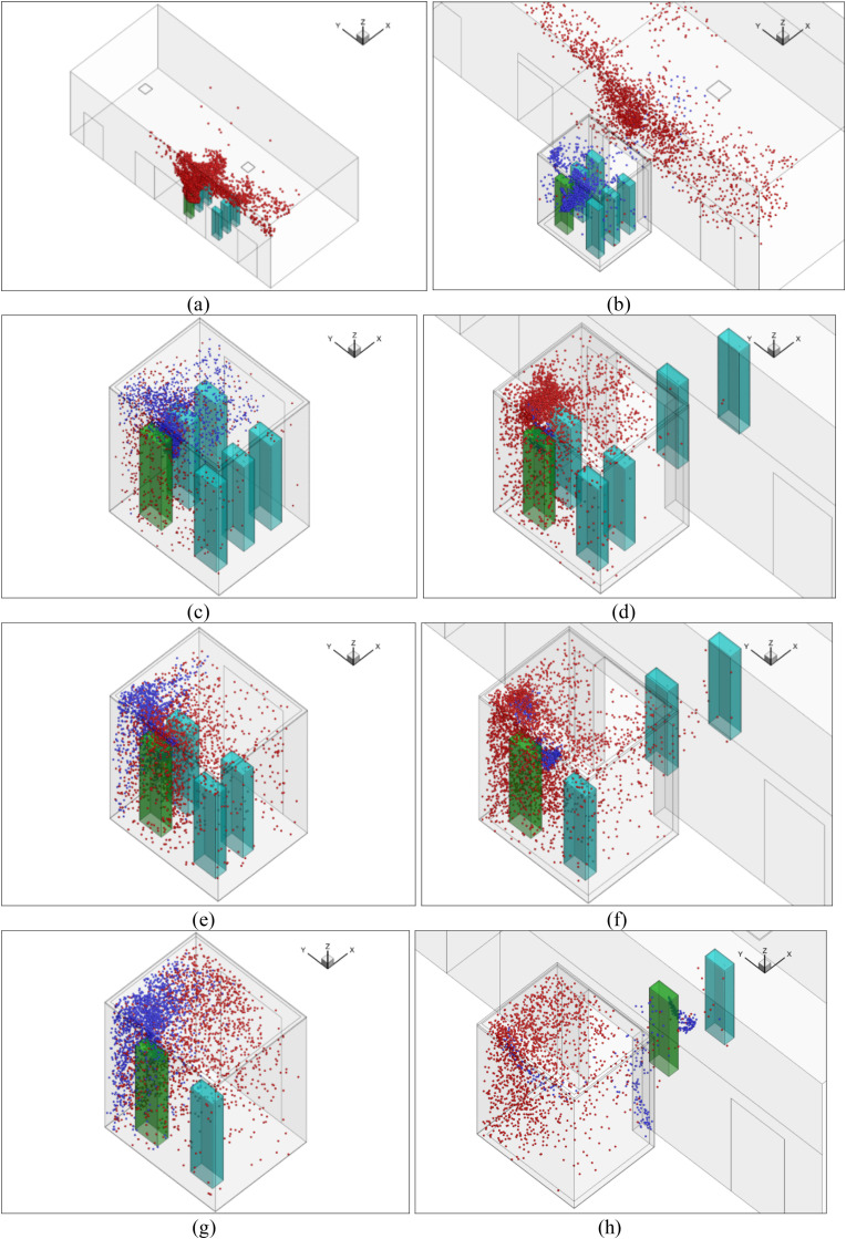
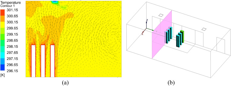
This subsection shows our simulated particle distributions for the reference case with the validated CFD model. Fig. 8 (a) shows the temporal distributions of particles in the lobby of floor 1 (sub-case 1) when the passengers were waiting for the elevator. The particles came from the continuous breathing of the index person (person in green color). The particles traveled upward due to the thermal plumes formed by the passengers as well as the ventilation, as shown in Fig. 9 (a). The temperature distribution around the persons of sub-case 1 for the reference case can be found in Fig. A1 in Appendix I. The lobby was large and was also connected to other building spaces through the two ends. The general ventilation in the lobby brought the particles away from those people so there were almost no particles reaching the breathing zone of those people, despite the waiting time of 30 s.
Fig. 8.
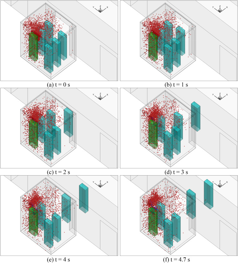
Particle distributions of different sub-cases: (a) sub-case 1, (b) sub-case 2, (c) sub-case 3, (d) sub-case 4, (e) sub-case 5, (f) sub-case 6, (g) sub-case 7, and (h) sub-case 8. (Red particles were those from the previous sub-case and the blue particles were newly generated by the index person through breathing for the next sub-case.). (For interpretation of the references to color in this figure legend, the reader is referred to the Web version of this article.)
Fig. 9.
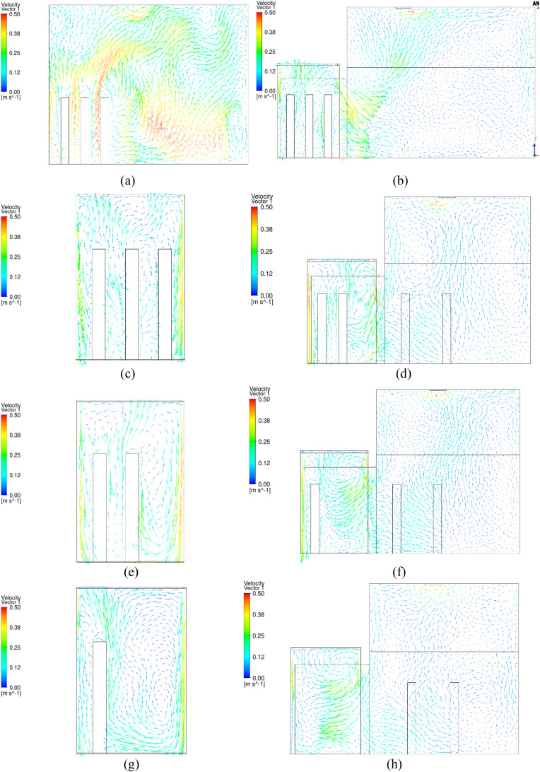
Velocity distributions in the surfaces through the index person of different sub-cases: (a) sub-case 1, (b) sub-case 2, (c) sub-case 3, (d) sub-case 4, (e) sub-case 5, (f) sub-case 6, (g) sub-case 7, and (h) sub-case 8.
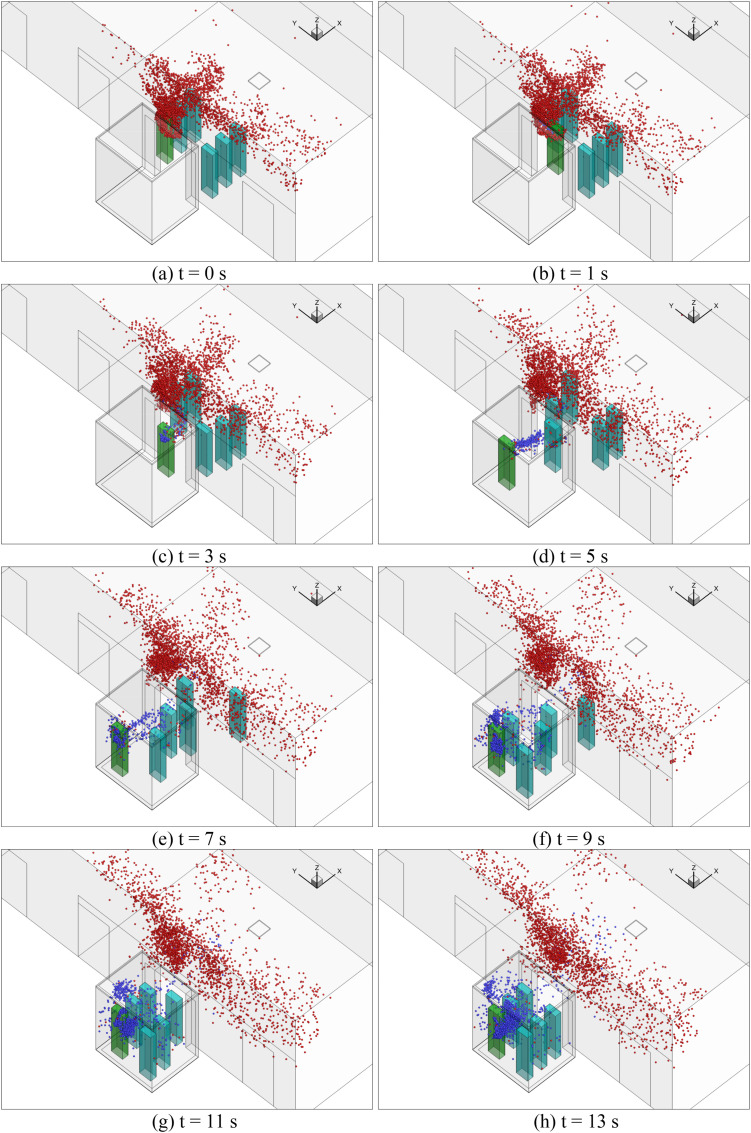
In sub-case 2, the passengers moved successively into the elevator cab in sub-case 2. The flow domain that was simulated included the lobby and the elevator cab, and the movement of the passengers was also simulated. Fig. 8(b) shows the particle distributions of sub-case 2. Note that we used the particle and airflow distributions from the previous sub-case (sub-case 1) as the initial conditions to conduct the numerical simulation. Therefore, the red particles were those from sub-case 1, and the blue particles were newly generated by the index person through breathing for sub-case 2. The result was that some red particles were carried as the passengers walked into the elevator cab due to the wakes generated by their movements, as shown in Fig. 9(b). More detailed temporal distributions of particles of sub-case 2 for the reference case can be found in Fig. A3 in Appendix II.
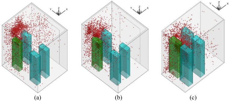
Fig. 8(c) shows the particle distribution of sub-case 3. When the passengers took the elevator from floor 1 to floor 10, the total ride time was 16 s. At the end of the trip, some red particles from sub-case 2 were still suspended in the air. The newly generated blue particles were mainly concentrated around the index person because it was difficult to disperse in the small space. The particle distributions were highly non-uniform. Fig. 9(c) shows the velocity distribution in the cab. The airflow around the persons mainly goes upward due to the thermal plume generated from the manikin and the ventilation.
Sub-case 4 was when the elevator reached floor 10, the elevator door opened, and two passengers walked out of the elevator. Fig. 8 (d) shows the particle distributions of the sub-case. Due to the wakes generated by the walking passengers, as shown in Fig. 9(d), some particles were carried into the lobby on floor 10. However, most of the particles remained in the elevator. Since the total walking time was only 4.7 s, the newly generated particles from the index person were confined in their vicinity. Most suspended particles were from the previous sub-case. More detailed temporal distributions of particles of sub-case 4 for the reference case can be found in Fig. A4 in Appendix II. When the elevator moved from floor 10 to 20 for 16 s in sub-case 5, the particle distributions were similar to sub-case 3 but with a much higher particle concentration as shown in Fig. 8 (e). When two more people left the elevator on floor 20, Fig. 8(f) shows very similar particle distributions to sub-case 4. Also, sub-case 7 was almost the same as sub-case 5, and sub-case 8 was nearly the same as sub-case 6. The major difference was the increasing particle concentration.
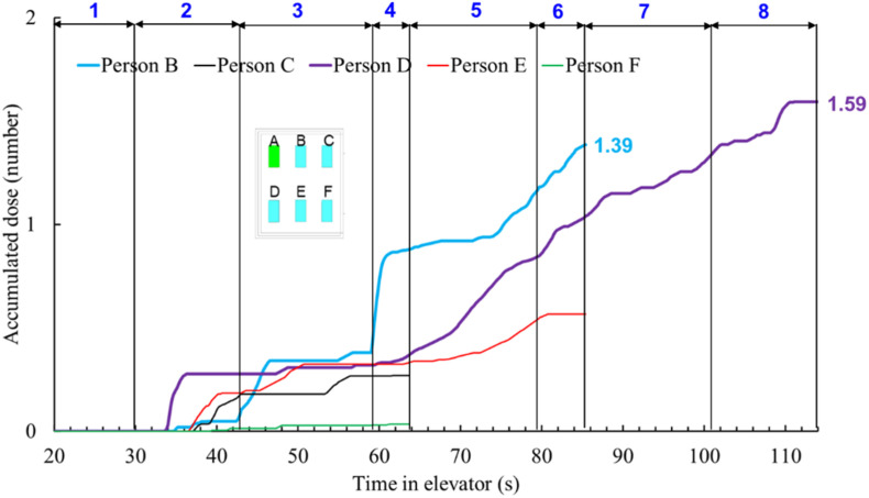
Fig. 10 depicts the accumulated dose of each person in the reference case. The blue numbers of 1–8 on the top of the figure represent the time span for each of the eight sub-cases. When each passenger left the elevator cab, their accumulated dose would stop at that time. The dose for passenger B was the highest before the person left on floor 20, because that passenger was in front of the index person. Passenger D stood side by side with and was also close to the index person; the accumulated dose was the highest because of the longest duration with the index person.
Fig. 10.
Accumulated dose for each passenger in the reference case.
3.3. Impact of particle sources on accumulated doses
Particles generated by an index person could come from breathing, talking, coughing and sneezing. The reference case used breathing data from Fabian et al. [51] as the particle source. This study also designed another case with coughing. Unlike the breathing scenario, coughing does not occur very frequently. For a 2-min elevator ride, a person may not even cough once. Nevertheless, this study assumed that the index person would cough once after all the riders had entered the elevator at floor 1 and the elevator door was closed, i.e. sub-case 3 as shown in Fig. 3.
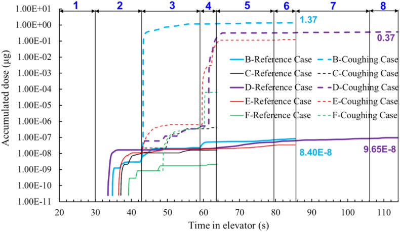
To compare coughing with breathing, the coughing case was designed without breathing, which is physically unrealistic but numerically feasible. This design would give us a clear picture of the differences between the two cases. Fig. 11 compares the accumulated particle mass doses of each passenger in the reference case with those in the coughing case. Due to the much larger size and much higher number of particles in a cough, the particle mass doses in the coughing case were approximately 8 orders of magnitude higher than those of the reference (breathing) case. Note that this comparison was based on the whole exposure time with continuous breathing and one single cough.
Fig. 11.
Comparison of the accumulated particle mass doses inhaled in the reference (breathing) case with those in the coughing case.
The results clearly show that particle source is particularly important in determining the airborne particle exposure. The coughing case led to a much more risky indoor environment than breathing for the elevator ride. Since coughing was not a continuous process, the results had much higher uncertainty. On the other hand, talking could be a more likely scenario in an elevator ride, which also produces large particles.
For a small and crowded place like the elevator, close-contact transmission should be important. We compared the particle deposition on surfaces inside elevators due to breathing and coughing. Fig. 12 depicts the particle deposition on manikin surfaces as well as the particle concentration in the cab for sub-case 3. In the breathing case, most particles go upward due to the thermal plume generated by the infected person. Therefore, some particles will deposit on the ceiling of the elevator. However, for coughing case, most particles will deposit on the manikin in front of the infected person as well as on the floor due to the coughing jet. It is suggested to cover the mouth when coughing or wear a mask.
Fig. 12.
Particle deposition on manikin surfaces as well as the particle concentration in the cab: (a) Particle deposition on manikin surfaces for breathing, (b) Breathing jet, (c) Particle concentration in the cab for breathing, (d) Particle deposition on manikin surfaces for coughing, (e) Coughing jet, (f) Particle concentration in the cab for coughing.
3.4. Impact of ventilation rate and method on accumulated doses
Since breathing is a continuous process and has a low uncertainty, this investigation selected breathing as the particle source for further evaluation of airborne particle exposure in taking the elevator. Ventilation rate and method are always important for determining the dose of susceptible people. Therefore, this sub-section reports our research results on the subject.
3.4.1. Comparison of different flow rate due to mechanical ventilation and infiltration
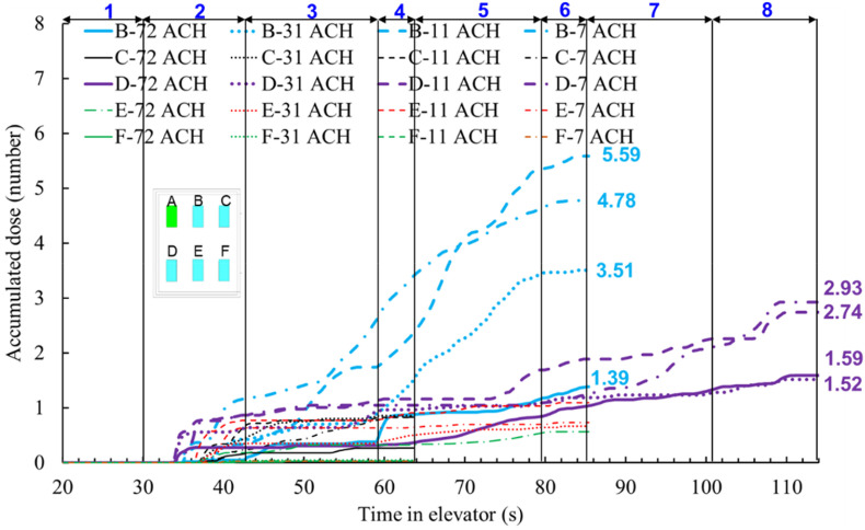
Elevators have different ventilation rates according to their design and applications. The reference case had a ventilation rate of 0.165 m3/s (72 ACH). This study investigated three other flow rates: mechanical ventilation with 0.071 m3/s (31 ACH) and 0.026 m3/s (11 ACH) and infiltration through vents and other openings with 0.017 m3/s (7 ACH). Fig. 13 compares the accumulated particle dose of each passenger of the four cases under different flow rates. The dose for passenger B was the highest before the person left on floor 20 because the passenger stood at the front of the index person. The accumulated doses for passenger B after they left on floor 20 were 1.39 particles for 72 ACH, 3.51 particles for 31 ACH, 5.59 particles for 11 ACH, and 4.78 for 7 ACH, respectively. The accumulated doses for passenger D, who went all the way with the index person to the top floor, were 1.59 particles for 72 ACH, 1.52 particles for 31 ACH, 2.74 particles for 11 ACH, and 2.93 for 7 ACH, respectively. The dose for passenger D with 7 ACH was lower versus 11 ACH because of the highly non-uniform distribution of the particles in the cab. Another such difference existed between 11 ACH mechanical ventilation and 7 ACH infiltration, where the dose inhaled by passenger B with 11 ACH was higher than those with 7 ACH infiltration.
Fig. 13.
Accumulated dose for each passenger of three cases with different ventilation rate (72 ACH, 31 ACH, 11 ACH, and 7 ACH).
3.4.2. Comparison of different air supply direction
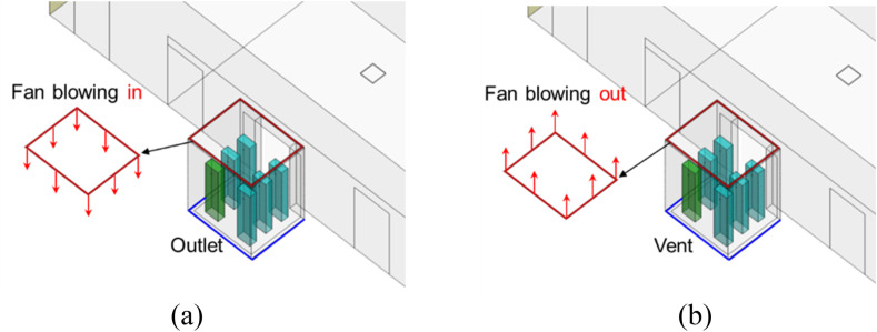
This investigation explored the impact of air supply direction on particle dispersion. For the reference case with a fan blowing inwards, the air was supplied from the inlet installed around the edges of a drop-ceiling and exhausted from vents at floor-level as shown in Fig. 14 . For comparison, we studied an exhaust fan scenario that simply reversed the fan flow direction. Except for the air supply direction, all the other settings were the same.
Fig. 14.
Schematic of the reference case and the fan blowing out scenario: (a) Fan blowing in scenario (reference case) (b) Fan blowing out scenario.
Fig. 15 compares the accumulated particle dose (particle number) over time for the fan blowing in case (reference case) and the fan blowing out case. Except for passengers B and D, the accumulated doses of other passengers were almost the same for both cases. In addition, the accumulated dose inhaled by passengers B and D for the exhaust fan scenario was much higher than in the reference case. This was because the dose for passenger D in the exhaust fan case increased quickly in sub-case 7 and the final dose was much higher than in the reference case.
Fig. 15.
Comparison of the accumulated particle dose by each passenger with different supply airflow direction in the elevator (solid lines for fan blowing in and dash lines for fan blowing out).
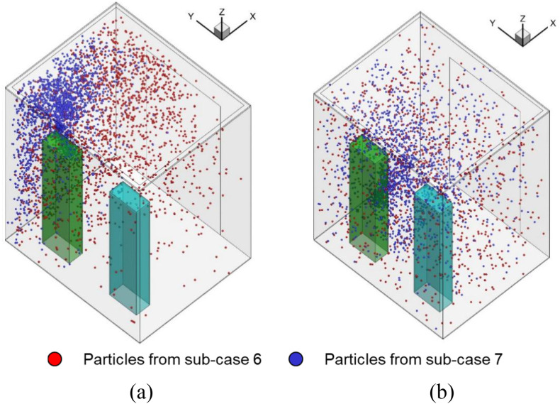
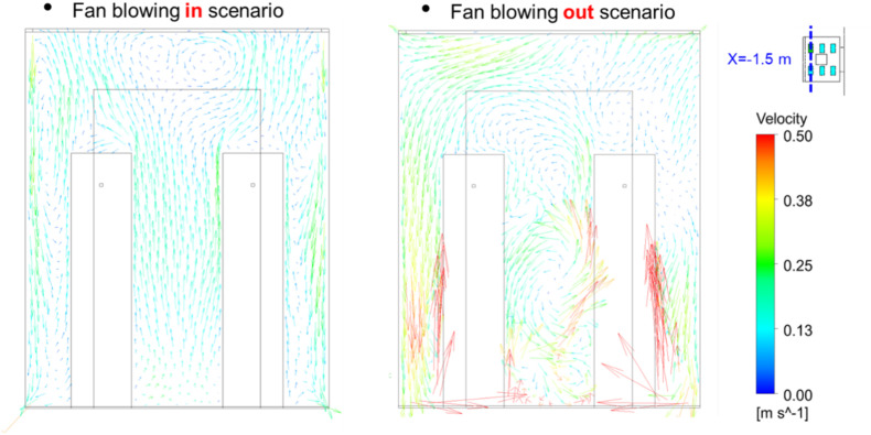
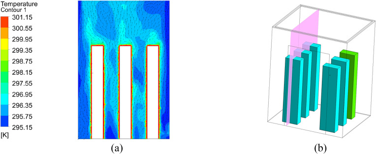
Fig. 16 shows the particle distributions when the elevator reached floor 35. The particle distribution of the fan blowing out scenario was more evenly distributed than that of the fan blowing in scenario, which causes a much higher particle concentration around the breathing zone of person D. Fig. 17 further shows the airflow at a cross-section through the two persons. The air velocity in most parts of the fan blowing out scenario was higher than that in the fan blowing in scenario. It made the particle inside the cab more evenly distributed. Note that although the air flow downwards by fan blowing in scenario, however, the air around the persons is going upward due to the thermal plume generated from the persons as well as the ventilation, as shown in Fig. 17 and Fig. A2 in Appendix I. The particles will follow the airflow pattern around the person and go upward. Therefore, most particles are gathered on the top of the cab.
Fig. 16.
Comparison of the particle distributions in the fan blowing in scenario and the fan blowing out scenario when the elevator reached floor 35: (a) Fan blowing in scenario (b) Fan blowing out scenario.
Fig. 17.
Comparison of the airflow at a cross section with different air supply direction.
3.5. Impact of elevator geometry on accumulated doses
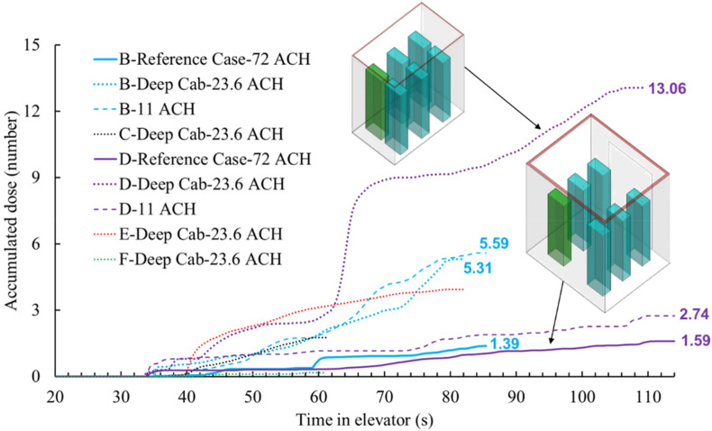
To investigate the impact of cab geometry on particle dispersion when riding the elevator, this study selected one deep cab to compare to the reference case as shown in Fig. 18 for further study. The dimensions of the reference cab were 2 m wide × 1.65 m deep × 2.5 m high and the deep cab was 1.1 m wide × 1.8 m deep × 2.2 m high. The deep cab used in this study was representative of a residential size or a typical European size. The ventilation rates for the reference cab and deep cab were 0.165 m3/s (72 ACH) and 0.026 m3/s (23.6 ACH), respectively, which was typical for the two cab types. The air supply in both cases was from the inlet around the ceiling, and the air was exhausted from the outlet near the floor.
Fig. 18.
Comparison of the accumulated particle dose for each passenger in different cabs.
Fig. 18 compares the accumulated particle dose for each passenger in the different cabs. Since both the geometry and ventilation rate of the reference case was different from the deep cab, this study also added another case (11 ACH in the legend) that had the same geometry as the reference cab and the same flow rate (0.026 m3/s) as the deep cab for comparison. The final accumulated dose for passenger D in the deep cab was almost 6 times that of the reference case. When passengers B and D were in the elevator at the same time, passenger B inhaled more particles than passenger D in both the reference case and the case with the lower ventilation rate of 0.026 m3/s. However, the corresponding result in the deep cab was the opposite. That was because the distance between passengers B and E in the deep cab was smaller than that in the reference case, which caused high movement of particles in the y-direction in the deep cab. This can be clearly seen in Fig. 19 .
Fig. 19.
Particle distributions in the elevator cab with different geometry and ventilation rate: (a) Reference case with 0.165 m3/s (72 ACH), (b) Same as the reference case but 0.026 m3/s (11 ACH), (c) Deep cab with 0.026 m3/s (23.6 ACH).
4. Discussion
This investigation had the following limitations:
-
•
Since the numerical simulation of the entire process was very time-consuming, this study separated the whole process into eight sub-cases and transferred data after each sub-case simulation. Since the mesh for each case could not be exactly the same, some errors may have been introduced.
-
•
Although we needed to simulate the movement of people by walking, using a real-shaped person would have demanded tremendous computing resources. In addition, Nielson [52] found that there was not a big difference in heat transfer and airflow patterns between a real-shaped person and a simplified person. Therefore, this study used a rectangular column to simulate a person.
-
•
We assumed the air conditioning systems in the lobby of floor 1 supplied fresh air in the ceiling and that the lobby was connected with other spaces. Therefore, the outlets were assigned at the two connection walls. For the particular case we simulated, all the particles from the index person moved upward and then to other spaces. The exposure of all other susceptible riders was almost zero. In reality, this may not always be true, as a wait time of 30 s is pretty long to be in close proximity to others in an environment with potentially stagnant air. One should not neglect the impact of exposure on the susceptible riders in an elevator lobby.
-
•
This investigation only validated the simulation method for airflow and particle concentration of steady process. Further investigation is needed to verify the unsteady process of human walking.
-
•
This investigation assumed that the building has 35 floors, the persons that riding the elevator are six, and stand regularly inside the elevator, two persons are going out on 10th floor and two persons going out on the 20th floor, the index person went the whole 35 floors, the persons leave the elevator one by one, but not simultaneously. The coughing occurred immediately after the person entered the elevator. The setting of the scenario seems to be not general. More scenarios should be considered in future investigations.
-
•
Since the numerical simulation of the process of particles being breathed into the lung of the susceptible person is very complicated and time-consuming, this investigation used a simple equation to calculate the accumulated dose of the susceptible person. Some errors may have been introduced.
5. Conclusions
This investigation used CFD to study airborne particle transmission of COVID-19 in riding an elevator in a typical building with 35 floors. The study calculated the accumulated dose of susceptible riders in riding elevators. The study led to the following conclusions:
-
•
Due to the short duration of the elevator ride, elevators with high ventilation had low particle exposure. For the reference case with a 72 ACH ventilation rate, the highest accumulated particle dose by a susceptible passenger close to the index person was only 1.59.
-
•
Because of the highly non-uniform distribution of the particles in the elevator cab, the accumulated dose was not inversely proportional with the ventilation rate. The dose for passenger B was the highest before they left on floor 20 because this passenger stood at the front of the index person. The accumulated dose for passenger D was the second-highest in the wide cab or the highest in the deep cab. This is because a deep cab could trap the particles inside the elevator. The air supply direction had an impact on the particle dispersion in the elevator cab.
-
•
This study assumed an index person would cough once when the person entered the elevator. The cough would cause other riders to inhale approximately 8 orders of magnitude higher particle mass than from continuous breathing by the index person for the whole duration of the ride.
Declaration of competing interest
The authors declare that they have no known competing financial interests or personal relationships that could have appeared to influence the work reported in this paper.
Acknowledgment
This study was partially supported by the National Natural Science Foundation of China (NSFC) through grant No. 52108084, by the China Postdoctoral Science Foundation through Grant No. 2020M680886, and by Jiangsu Planned Projects for Postdoctoral Research Funds through Grant No. 2021K069A (1103000286).
Appendix ITemperature distribution of different sub-cases for the reference case
Fig. A1.
Simulated results of sub-case 1 for the reference case: (a) temperature and velocity distribution in the surface across three persons, (b) location of the surface.
Fig. A2.
Simulated results of sub-case 3 for the reference case: (a) temperature and velocity distribution in the surface across three persons, (b) location of the surface.
Appendix II. Temporal distributions of particles due to breathing from the index person of different sub-cases for the reference case
Fig. A3.
Temporaral particle distributions of sub-case 2 for the reference case (Red particles were those from the previous sub-case and the blue particles were newly generated by the index person through breathing for the next sub-case.).
Fig. A4.
Temporaral particle distributions of sub-case 4 for the reference case (Red particles were those from the previous sub-case and the blue particles were newly generated by the index person through breathing for the next sub-case.).
References
- 1.Xie C., Zhao H., Li K., et al. The evidence of indirect transmission of SARS-CoV-2 reported in Guangzhou, China. BMC Publ. Health. 2020;20(1):1–9. doi: 10.1186/s12889-020-09296-y. [DOI] [PMC free article] [PubMed] [Google Scholar]
- 2.https://edition.cnn.com/world/live-news/coronavirus-pandemic-06-30-20-intl/h_a595effdf2c206c4e627f5082726284d
- 3.https://finance.sina.com.cn/tech/2020-11-24/doc-iiznctke3078904.shtml
- 4.Chen J., He H., Cheng W., et al. Potential transmission of SARS-CoV-2 on a flight from Singapore to Hangzhou, China: an epidemiological investigation. Trav. Med. Infect. Dis. 2020;36:101816. doi: 10.1016/j.tmaid.2020.101816. [DOI] [PMC free article] [PubMed] [Google Scholar]
- 5.Khanh N.C., Thai P.Q., Quach H.L., et al. Transmission of SARS-CoV 2 during long-haul flight. Emerg. Infect. Dis. 2020;26(11):2617–2624. doi: 10.3201/eid2611.203299. [DOI] [PMC free article] [PubMed] [Google Scholar]
- 6.Speake H., Phillips A., Chong T., et al. Flight-associated transmission of severe acute respiratory syndrome coronavirus 2 corroborated by whole-genome sequencing. Emerg. Infect. Dis. 2020;26(12):2872. doi: 10.3201/eid2612.203910. [DOI] [PMC free article] [PubMed] [Google Scholar]
- 7.Li Y., Qian H., Hang J., et al. Probable airborne transmission of SARS-CoV-2 in a poorly ventilated restaurant. Build. Environ. 2021;196:107788. doi: 10.1016/j.buildenv.2021.107788. 04.16.20067728. [DOI] [PMC free article] [PubMed] [Google Scholar]
- 8.Liu X., Wu J., Liu M., et al. 2020. Presymptomatic Transmission of COVID-19 in a Cluster of Cases Occurred in Confined Space: a Case Report. [Google Scholar]
- 9.WHO . World Health Organization; 2020. Modes of Transmission of Virus Causing COVID-19: Implications for IPC Precaution Recommendations: Scientific Brief, 27 March 2020. [Google Scholar]
- 10.Domingo J.L., Marquès M., Rovira J. Influence of airborne transmission of SARS-CoV-2 on COVID-19 pandemic. A review. Environ. Res. 2020;188:109861. doi: 10.1016/j.envres.2020.109861. [DOI] [PMC free article] [PubMed] [Google Scholar]
- 11.Hadei M., Hopke P.K., Jonidi A., et al. A letter about the airborne transmission of SARS-CoV-2 based on the current evidence. Aerosol and Air Quality Research. 2020;20(5):911–914. [Google Scholar]
- 12.Klompas M., Baker M.A., Rhee C. Airborne transmission of SARS-CoV-2: theoretical considerations and available evidence. Jama. 2020;324(5):441–442. doi: 10.1001/jama.2020.12458. [DOI] [PubMed] [Google Scholar]
- 13.Ren C., Xi C., Feng Z., et al. 2021. Mitigating COVID-19 Infection Disease Transmission in Indoor Environment Using Physical Barriers. [DOI] [PMC free article] [PubMed] [Google Scholar]
- 14.Wang J., Huang J., Feng Z., et al. Occupant-density-detection based energy efficient ventilation system: prevention of infection transmission. Energy Build. 2021;240:110883. doi: 10.1016/j.enbuild.2021.110883. [DOI] [PMC free article] [PubMed] [Google Scholar]
- 15.Liu Z., Zhuang W., Hu L., et al. Experimental and numerical study of potential infection risks from exposure to bioaerosols in one BSL-3 laboratory. Build. Environ. 2020;179:106991. doi: 10.1016/j.buildenv.2020.106991. [DOI] [PMC free article] [PubMed] [Google Scholar]
- 16.Jin T., Li J., Yang J., et al. SARS-CoV-2 presented in the air of an intensive care unit (ICU) Sustainable cities and society. 2021;65:102446. doi: 10.1016/j.scs.2020.102446. [DOI] [PMC free article] [PubMed] [Google Scholar]
- 17.Zhou Y., Shen J. Experimental and numerical study on the transport of droplet aerosols generated by occupants in a fever clinic. Build. Environ. 2021;187:107402. doi: 10.1016/j.buildenv.2020.107402. [DOI] [PMC free article] [PubMed] [Google Scholar]
- 18.Yan Y., Li X., Yang L., et al. Evaluation of cough-jet effects on the transport characteristics of respiratory-induced contaminants in airline passengers' local environments. Build. Environ. 2020;183:107206. doi: 10.1016/j.buildenv.2020.107206. [DOI] [PMC free article] [PubMed] [Google Scholar]
- 19.Park S., Choi Y., Song D., et al. Natural ventilation strategy and related issues to prevent coronavirus disease 2019 (COVID-19) airborne transmission in a school building. Sci. Total Environ. 2021;789:147764. doi: 10.1016/j.scitotenv.2021.147764. [DOI] [PMC free article] [PubMed] [Google Scholar]
- 20.Nishiura H., Oshitani H., Kobayashi T., et al. 2020. Closed Environments Facilitate Secondary Transmission of Coronavirus Disease 2019 (COVID-19) MedRxiv. [Google Scholar]
- 21.Bhagat R.K., Wykes M.S.D., Dalziel S.B., et al. Effects of ventilation on the indoor spread of COVID-19. J. Fluid Mech. 2020:903. doi: 10.1017/jfm.2020.720. [DOI] [PMC free article] [PubMed] [Google Scholar]
- 22.Agrawal A., Bhardwaj R. Reducing chances of COVID-19 infection by a cough cloud in a closed space. Phys. Fluids. 2020;32(10):101704. doi: 10.1063/5.0029186. [DOI] [PMC free article] [PubMed] [Google Scholar]
- 23.Kong X., Guo C., Lin Z., et al. Experimental study on the control effect of different ventilation systems on fine particles in a simulated hospital ward. Sustainable Cities and Society. 2021:103102. doi: 10.1016/j.scs.2021.103102. [DOI] [PMC free article] [PubMed] [Google Scholar]
- 24.Dai H., Zhao B. Association of the infection probability of COVID-19 with ventilation rates in confined spaces. Building simulation. Tsinghua University Press. 2020;13(6):1321–1327. doi: 10.1007/s12273-020-0703-5. [DOI] [PMC free article] [PubMed] [Google Scholar]
- 25.Mazumdar S., Poussou S., Lin C.-H., et al. The impact of scaling and body movement on contaminant transport in airliner cabins. Atmos. Environ. 2011;45(33):6019–6028. [Google Scholar]
- 26.https://www.youtube.com/watch?v=MvLYHSODHVo
- 27.Cheng Y., Lin Z. Experimental investigation into the interaction between the human body and room airflow and its effect on thermal comfort under stratum ventilation. Indoor Air. 2016;26(2):274–285. doi: 10.1111/ina.12208. [DOI] [PubMed] [Google Scholar]
- 28.Poussou S.B., Mazumdar S., Plesniak M.W., et al. Flow and contaminant transport in an airliner cabin induced by a moving body: model experiments and CFD predictions. Atmos. Environ. 2010;44(24):2830–2839. [Google Scholar]
- 29.Choi J.I., Edwards J.R. Large‐eddy simulation of human‐induced contaminant transport in room compartments. Indoor Air. 2012;22(1):77–87. doi: 10.1111/j.1600-0668.2011.00741.x. [DOI] [PubMed] [Google Scholar]
- 30.Tao Y., Yang W., Inthavong K., et al. Indoor particle inhalability of a stationary and moving manikin. Build. Environ. 2020;169:106545. [Google Scholar]
- 31.Lim T., Cho J., Kim B.S. Predictions and measurements of the stack effect on indoorairborne virus transmission in a high-rise hospital building. Build. Environ. 2011;46:2413–2424. doi: 10.1016/j.buildenv.2011.04.015. [DOI] [PMC free article] [PubMed] [Google Scholar]
- 32.Shao S., Zhou D., He R., et al. Risk assessment of airborne transmission of COVID-19 by asymptomatic individuals under different practical settings. J. Aerosol Sci. 2021;151:105661. doi: 10.1016/j.jaerosci.2020.105661. [DOI] [PMC free article] [PubMed] [Google Scholar]
- 33.Dbouk T., Drikakis D. On airborne virus transmission in elevators and confined spaces. Phys. Fluids. 2021;33(1) doi: 10.1063/5.0038180. [DOI] [PMC free article] [PubMed] [Google Scholar]
- 34.Subbarao K., Mahanty S. Respiratory virus infections: understanding COVID-19. Immunity. 2020;52(6):905–909. doi: 10.1016/j.immuni.2020.05.004. [DOI] [PMC free article] [PubMed] [Google Scholar]
- 35.Shih T.H., Liou W.W., Shabbir A., et al. A new k-ε eddy viscosity model for high Reynolds number turbulent flows. Comput. Fluid. 1995;24(3):227–238. [Google Scholar]
- 36.Cheng Y., Lin Z. Experimental investigation into the interaction between the human body and room airflow and its effect on thermal comfort under stratum ventilation. Indoor Air. 2016;26(2):274–285. doi: 10.1111/ina.12208. [DOI] [PubMed] [Google Scholar]
- 37.Gupta J.K., Lin C.-H., Chen Q. Transport of expiratory particles in an aircraft cabin. Indoor Air. 2011;21:3–11. doi: 10.1111/j.1600-0668.2010.00676.x. [DOI] [PubMed] [Google Scholar]
- 38.Chen C., Zhao B. Some questions on dispersion of human exhaled droplets in ventilation room: answers from numerical investigation. Indoor Air. 2010;20(2):95–111. doi: 10.1111/j.1600-0668.2009.00626.x. [DOI] [PubMed] [Google Scholar]
- 39.Zhao B., Zhang Y., Li X., et al. Comparison of indoor aerosol particle concentration and deposition in different ventilated rooms by numerical method. Build. Environ. 2004;39(1):1–8. [Google Scholar]
- 40.Li A., Ahmadi G. Dispersion and deposition of spherical particles from point sources in a turbulent channel flow. Aerosol Sci. Technol. 1992;16(4):209–226. [Google Scholar]
- 41.Zhang H., Wang F., Wang Y., et al. CFD simulation of cooking particle distribution and motion. Procedia Engineering. 2017;205:1800–1806. [Google Scholar]
- 42.Elghobashi S. On predicting particle-laden turbulent flows. Appl. Sci. Res. 1994;52(4):309–329. [Google Scholar]
- 43.Ansys Fluent . ANSYS, Inc; Canonsburg, Pennsylvania, USA: 2014. User's and Theory Guide. 14.5. [Google Scholar]
- 44.Gambit CFD . Fluent Inc.; Lebanon, NH: 1998. User's Guide. Preprocessor. [Google Scholar]
- 45.Liu S., Xu L., Chao J., et al. Thermal environment around passengers in an aircraft cabin. HVAC R Res. 2013;19(5):627–634. [Google Scholar]
- 46.Chao C.Y.H., Wan M.P., Morawska L., et al. Characterization of expiration air jets and particle size distributions immediately at the mouth opening. J. Aerosol Sci. 2009;40(2):122–133. doi: 10.1016/j.jaerosci.2008.10.003. [DOI] [PMC free article] [PubMed] [Google Scholar]
- 47.Shi Z., Lu Z., Chen Q. Indoor airflow and contaminant transport in a room with coupled displacement ventilation and passive-chilled-beam systems. Build. Environ. 2019;161:106244. [Google Scholar]
- 48.Srivastava S., Zhao X., Manay A., et al. Effective ventilation and air disinfection system for reducing coronavirus disease 2019 (COVID-19) infection risk in office buildings. Sustainable Cities and Society. 2021;75:103408. doi: 10.1016/j.scs.2021.103408. [DOI] [PMC free article] [PubMed] [Google Scholar]
- 49.You R., Lin C.-H., Wei D., et al. Evaluating the commercial airliner cabin environment with different air distribution systems. Indoor Air. 2019;29(5):840–853. doi: 10.1111/ina.12578. [DOI] [PubMed] [Google Scholar]
- 50.Zhang Z., Chen Q. Experimental measurements and numerical simulations of particle transport and distribution in ventilated rooms. Atmos. Environ. 2006;40(18):3396–3408. [Google Scholar]
- 51.Fabian P., McDevitt J.J., DeHaan W.H., et al. Influenza virus in human exhaled breath: an observational study. PLoS One. 2008;3(7) doi: 10.1371/journal.pone.0002691. [DOI] [PMC free article] [PubMed] [Google Scholar]
- 52.Nielsen P.V. Benchmark test for a computer simulated person. Indoor Air. 2003;14(7):144–156. [Google Scholar]


