Abstract
With a better balance among good mechanical performance, high freedom of design, and low material and manufacturing cost, chopped carbon fiber chip reinforced sheet molding compound (SMC) composites show great potential in different engineering applications. In this paper, bending fatigue behaviors of SMC composites considering the heterogeneous fiber orientation distributions have been thoroughly investigated utilizing both experimental and computational methods. First, four-point bending fatigue tests are performed with designed SMC composites, and the local modulus is adopted as a metric to represent the local fiber orientation of two opposing sides. Interestingly, SMC composites with and without large discrepancy in local modulus of opposing sides show different fatigue behaviors. Interrupted tests are conducted to explore the bending fatigue failure mechanism, and the damage processes of valid specimens are also closely examined. We find that the fatigue failure of SMC composites under four-point bending is governed by crack propagation instead of crack initiation. Because of this, the heterogeneous local fiber orientations of both sides of the specimen influence fatigue life. The microstructure of the lower side shows a direct influence while that of the upper side also exhibiting influence which becomes more prominent for high cycle fatigue cases. Furthermore, a hybrid micro-macro computational model is proposed to efficiently study the cyclic bending behavior of SMC composites. The region of interest is reconstructed with a modified random sequential absorption algorithm to conserve all the microstructural details including the heterogeneous fiber orientation, while the rest of the regions are modeled as homogenized macro-scale continua. Combined with a framework to capture the progressive fatigue damage under cyclic bending, the bending fatigue behaviors of SMC composites are accurately captured by the hybrid computational model comparing with our experimental analysis.
Keywords: chopped carbon fiber chip reinforced composites, sheet molding compound, four-point bending fatigue, fiber orientation, hybrid micro-macro computational model
1. Introduction
Carbon fiber reinforced polymer (CFRP) composites, such as unidirectional fiber reinforced composites [1–9], woven textile composites [10–14], short fiber reinforced composites [15–20], and chopped fiber chip reinforced composites [21–24], show prominent advantages as lightweight alternatives to metals. In particular, chopped carbon fiber chip reinforced sheet molding compound (SMC) composites can reach a better balance among good mechanical performance, high freedom of design, and low material and manufacturing cost. SMC composites have become one of the most promising materials in structural components in the automotive, marine, and aerospace industries, e.g., vehicle hood, hatchback, and guide vane of gas turbine engines [25, 26]. Then, a comprehensive understanding of the material performance under these operating conditions is important to ensure their safe applications.
Over the last decade, a number of studies on the internal microstructure, mechanical behavior, and fatigue performance of SMC composites have been performed. The heterogeneity and anisotropy at the macro-scale level have been demonstrated to be correlated with the internal microstructures. Feraboli et al. [21, 27–29], Selezneva et al. [30–32], Wan et al. [33, 34], and Johanson et al. [35] have evaluated the material properties of SMC composites fabricated by different manufacturing processes. The variations of microstructure and local modulus in SMC composites have been observed with advanced testing techniques, including Digital Image Correlation (DIC) and ultrasound C-scan instruments. Using similar equipment, our previous work [36] has revealed the correlation among tensile failure, local modulus, and fiber orientation distribution for different types of SMC composites. Further, a constant fatigue life diagram of SMC composites is established based on the fiber orientation tensor [37]. Nony-Davadie et al. [38] have also investigated the mechanical and fatigue behavior of randomly and highly oriented SMC composites, and the anisotropy induced by the thermo-compression process is pronounced. Recently, Martulli et al. [39–42] have linked the tensile, compression, and fatigue properties of SMC composites with the morphology captured using X-ray micro-CT. Meanwhile, Alves et al. [43, 44] have improved the strength of SMC composites via a physically-based model for microstructural design [45]. The optimal microstructure has been fabricated and tested, which is closing the gap to quasi-isotropic continuous-fiber laminates.
In addition, numerical simulations with microstructure- or mesostructure-based models to predict the material properties of SMC composites have also been widely conducted. Representative volume element (RVE) models generated by different algorithms have been employed in the stiffness analysis as well as quasi-static/cyclic failure predictions for SMC composites. Feraboli et al. [29] have developed a random RVE model, in which statistical distributions of fractions and orientations of chips are generated with a randomization process. The elastic properties can be predicted when the classical laminated plate theory is applied. Selezneva et al. [32] have established a stochastic finite element technique, in which the variability is modeled with randomly oriented strands, and then the strength can be predicted based on Hashin’s failure criteria and fracture energies. Harper et al. [46] have reconstructed the 3D geometry of discontinuous fiber composites by using a force-directed algorithm, and a high fiber volume fraction (~50%) is achieved. Li et al. [47] have built up a Voronoi diagram-based algorithm to reconstruct substructure features of chips in SMC composites. It has a unique advantage as the modulus of SMC composites can be predicted based on the material processing information. Meanwhile, we have proposed the voxel-based and conforming-based RVE models for SMC composites, respectively [48, 49], and we have demonstrated that the uniaxial mechanical and fatigue behavior of SMC composites under different loadings can be well reproduced with the conforming-based algorithm [49–52]. Sommer et al. [53–55] and Kravchenko et al. [56, 57] take a step further and integrate the compression molding simulation, meso-structure reconstruction, and tensile property prediction.
SMC components in real-world applications are large-scale structural components, which are more often subjected to out-of-plane load [58, 59]. However, the research works on the bending behavior are limited for carbon fiber SMC composites. Palmer et al. [60] have compared the flexural strength of recycled carbon and glass fiber SMC composites. Ogi et al. [61] have analyzed the effect of temperature on the flexural strength of carbon fiber SMC composites. Lee et al. [62] have evaluated the effect of carbon fiber content on the tensile and flexural behavior of carbon fiber SMC composites. Ishikawa et al. [63] have pointed out that bending strength and modulus are correlated with the local fiber orientation distribution. Martulli et al. [42] have analyzed the bending behavior of automotive components fabricated with carbon fiber SMC composites, and the effect of manufacturing conditions on the mechanical performance has been evaluated with X-ray micro-CT. Despite these efforts, the cyclic bending behavior of carbon fiber SMC composites, especially the effect of local fiber orientation distribution, remains uncharted. However, it is extremely significant in the performance prediction and optimal design of these large-scale structural components.
This paper aims to explore the bending fatigue behavior of carbon fiber SMC composites by utilizing both experimental and numerical methods. First, four-point bending fatigue tests are performed with designed SMC specimens, and the local modulus is adopted as a metric to characterize the local fiber orientation distribution of two opposing sides. The effect of heterogeneous fiber orientation distribution of both sides of the specimen on the bending fatigue performance is systematically compared. Meanwhile, the interrupted tests are performed to explore the bending fatigue failure mechanism. Next, a hybrid micro-macro computational model is generated to simulate the cyclic bending behavior of SMC composites. The region of interest is reconstructed with modified random sequential absorption (RSA) algorithm, while other regions are modeled as homogenized macro-scale continua. We then use the hybrid computational model integrating a progressive damage fatigue law to predict the bending fatigue performance of SMC composites.
2. Materials and Four-Point Bending Fatigue Test Setup
The chopped carbon fiber chip reinforced SMC composites used in the four-point bending fatigue tests are composed of pseudo-planar randomly distributed carbon fiber chips and vinyl ester resin matrix, which are the same as those in our previous work [37, 50]. Since the notch-insensitivity under different loadings has been demonstrated for SMC composites [50, 64, 65], a circular hole is introduced in all specimens to reduce the possibility of invalid results, e.g., the fractures around the pins. Note that notch-insensitivity is referred to that the failure strength is proportional to the net section (the cross-section at the hole area) as shown in Fig. 1, while the effect of notch-induced stress concentration is minor [66, 67]. As the cross-section area at the hole is smaller, specimens would still fail at the hole area despite notch-insensitivity. The specimen preparation is illustrated in Fig. 2. The dimensions of the four-point bending fatigue specimen are 274 mm × 60 mm × 4.8 mm. Though the fiber orientation distribution tends to be isotropic random globally for SMC composites, chips at the local areas may have a dominant orientation. Thus, before the four-point fatigue bending fatigue tests, the material heterogeneity measurement for the gauge section is performed through quasi-static pre-tension, during which the strain evolutions of two opposing surfaces are captured with two aligned DIC systems (ARAMIS). It has been shown that the local internal fiber orientation distribution can be correlated to the local modulus calculated by surface strain measured with DIC systems for SMC composites [36, 37]. To keep consistent with our previous work on the aspect ratio [36, 37, 49, 50], the local area with a spacing of 2 mm along the longitudinal direction is selected to calculate the local modulus. Since the local moduli measured from two opposing surfaces are different [36] and the stress states at two opposing sides are also different under four-point bending loading, the nominal modulus Enominal defined in Ref. [36] is introduced to describe the local fiber orientation distribution of either side (from the surface to the center),
| (1) |
where σ is the nominal stress under quasi-static pre-tension, and εlocal is the local surface strain captured from either side. Here, the effect of the internal microstructure at the opposing side (from the center to the opposing surface) on the surface strain evolution is not considered. The circular hole, the diameter of which is 12.7 mm, is positioned at the local area with a relatively lower nominal modulus, and the side with the relatively lower nominal modulus is set as the lower side, i.e., the tension-dominated side.
Fig. 1.
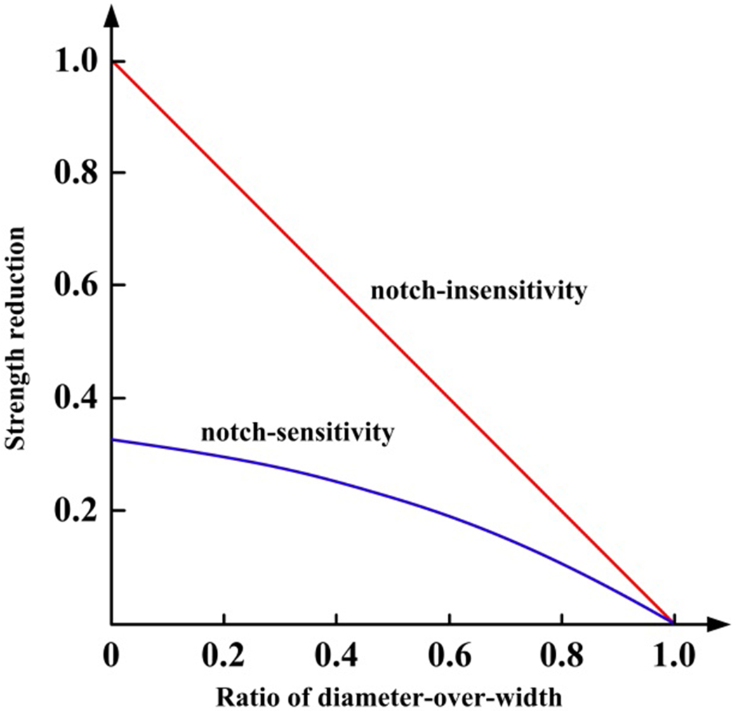
Schematic of notch-insensitivity vs. notch-sensitivity [66, 67]. The red straight line is referred to the strength reduction of notch-insensitive materials, which is only attributed to the reduced area at the net section. Blue curved line represents notch-sensitive materials, e.g., conventional metals.
Fig. 2.
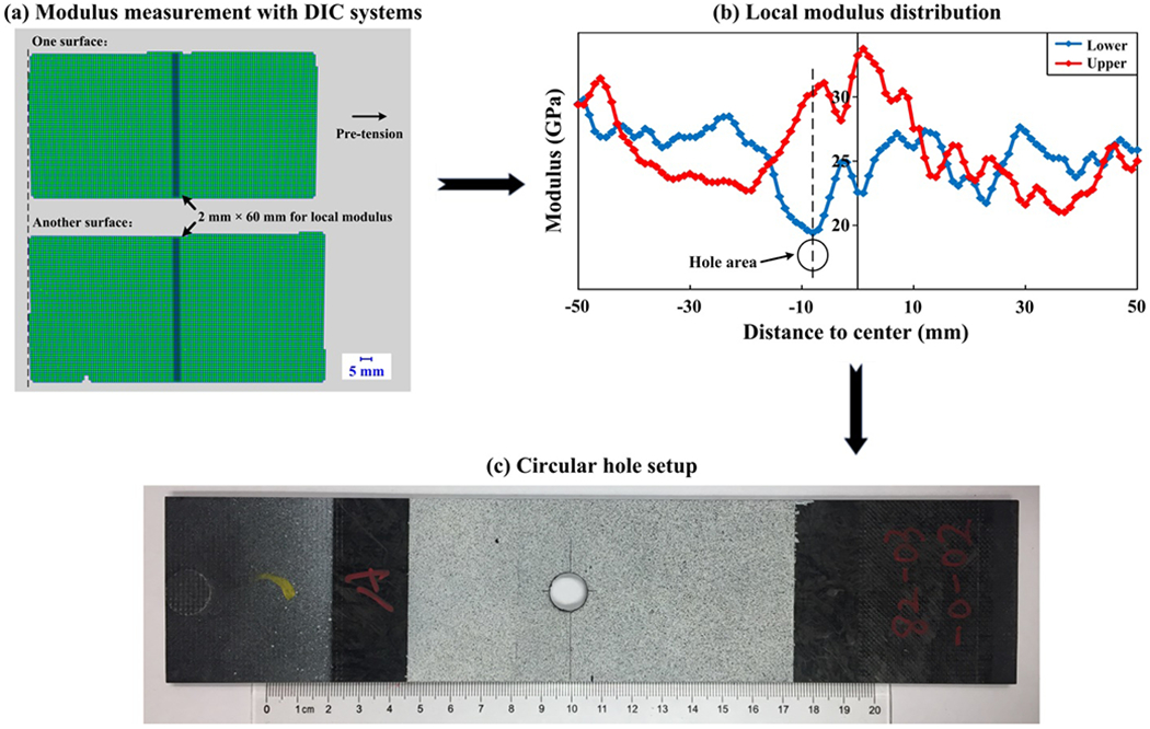
Specimen preparation and hole area determination for four-point bending fatigue tests for (a) modulus measurement with DIC systems, (b) local modulus distribution, and (c) circular hole setup. The strain evolutions of two opposing surfaces are measured under pre-tension (till ~100MPa).
An MTS servo-controlled hydraulic frame is used to perform four-point bending fatigue tests for SMC composites. The four-point bending fixture is shown in Fig 3. The loading and support spans are 100 mm and 200 mm, respectively. Double-sided tapes are used at the contact regions between specimen and fixture to suppress the sliding under cyclic bending. We conduct the load-controlled tests with a frequency of 2 Hz at an ambient temperature of 23 °C. The load ratio is 0.1. Afterwards, the interrupted tests are also designed to explore the failure processes of SMC composites under cyclic bending. The bending fatigue tests are suspended after a certain number of cycles, and the crack initiation and propagation around the circular hole will be analyzed.
Fig. 3.
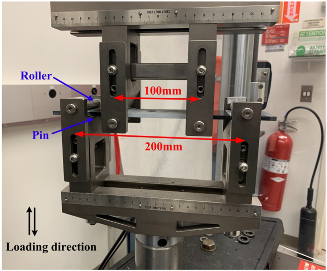
Four-point bending fatigue test setup using an MTS servo-controlled hydraulic frame. The loading and support spans are 100 mm and 200 mm, respectively.
3. Fatigue Results and Failure Mechanisms
Eighteen valid bending fatigue results are obtained from the four-point bending fatigue tests of SMC composites. The amplitude of theoretical bending stress is adopted to evaluate the loading level under cyclic bending. The theoretical bending stress is given as,
| (2) |
where F is the applied total force; L is the span between the loading and support pins; w is the width of the specimen; d is the diameter of the circular hole; t is the thickness of the specimen. The S-N data of SMC composites under four-point bending are collected in Fig. 4, and the corresponding bending fatigue life model can be given as,
| (3) |
where g1 = 119 MPa and g2 = −3E-3 are calibrated through nonlinear curve fitting of the valid bending fatigue results. Among those valid data (details are also listed in Appendix A), the stress amplitude ranges from 101 MPa to 127 MPa, which is generally higher than that of the uniaxial fatigue results (68 MPa to 99 MPa) collected in Ref. [37]. This is reasonable as the stress employed in the uniaxial fatigue model of SMC composites is the nominal stress. Under the uniaxial fatigue loading, the stress within the critical layers should be higher than the mean value (the nominal stress). Therefore, if the uniaxial fatigue model of SMC composites was applied in the present work directly, the fatigue life under cyclic bending would be underestimated. As shown in Fig. 4, owing to the variation of fiber orientation distribution at the critical local area, a large scatter can be observed in the obtained bending fatigue data, and no obvious correlation can be found between the stress amplitude and bending fatigue life, which is similar as the fatigue results under uniaxial fatigue loadings [37, 50].
Fig. 4.
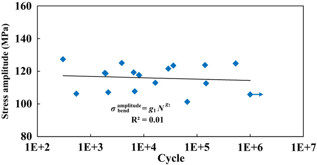
S-N data of SMC composites under bending fatigue loading.
During the setup of the four-point bending tests, the weaker side, which has the relatively lower nominal modulus, is placed at the lower side. It should be mentioned that the lower modulus is correlated to the situation that more chopped carbon fibers align along the transverse direction, and the fiber reinforcement is less pronounced. Then, the fatigue failure of SMC composites under cyclic bending will be tension-dominated in the present study, and the effect of fiber orientation distribution at the lower side is more prominent than that at the upper side. In general, the effect of fiber orientation distribution on quasi-static and fatigue strength can be considered in a consistent manner. Thus, the predicted quasi-static strength given by a linear equation of the local modulus has been adopted to characterize this effect on uniaxial fatigue loadings [37]. Following the normalized fatigue model of SMC composites with a stress ratio of 0.1 proposed in our previous work, the normalized bending fatigue model of SMC composites is given as,
| (4) |
where = 7.8E-3 and = 58 MPa are provided in Ref. [37], which are used to characterize the effect of local fiber orientation distribution on fatigue behavior of SMC composites with a stress ratio of 0.1, and is the nominal modulus at the lower side of the net section.
Different from conventional metals or CFRP composites, the material heterogeneity along the thickness direction is also distinct in SMC composites [35, 36]. It can be expected that if the bending fatigue failure of SMC composites is crack initiation dominated, then the bending fatigue life would be mainly determined by the internal microstructure of the lower side. However, if crack propagation dominates, the material property of the upper side would also have some influence on the bending life. Thus, in the present study, we also focus on the effect induced by material heterogeneity of two opposing sides and look into whether the upper side also shows influence in the fatigue behavior of SMC composites. In order to describe the discrepancy of the local fiber orientation distribution at upper and lower sides, the modulus deviation between upper and lower sides ξ is defined,
| (5) |
where is the nominal modulus at the upper side of the net section.
For convenience, the valid data are classified into two groups based on the measured ξ: group A (ξ < 0.5) and group B (ξ ≥ 0.5). The normalized S-N data of SMC composites under bending fatigue loading are drawn in Fig. 5. = 0.58 and = −2.2E-2 are fitted for group A data, while g3 = 0.57 and g4 = −1.2E-2 are calibrated for group B data. By considering this effect of local fiber orientation distribution, the correlation between the new failure parameter and bending fatigue life is significantly improved, and the correlation coefficient R2 increases from 0.01 to 0.71 for both groups. Note that the alignment of carbon fiber chips along the longitudinal direction corresponds to the increment of the modulus. Therefore, the bending fatigue strength of SMC composites increases when the carbon fiber chips are more aligned to the longitudinal direction, similar to the uniaxial fatigue behaviors [37]. The generality of the normalization with local modulus to characterize the effect of fiber orientation distribution is verified under cyclic bending. By comparison, the bending fatigue life becomes longer for SMC composites with a higher nominal modulus at the upper side, which becomes more remarkable for high cycle fatigue cases.
Fig. 5.
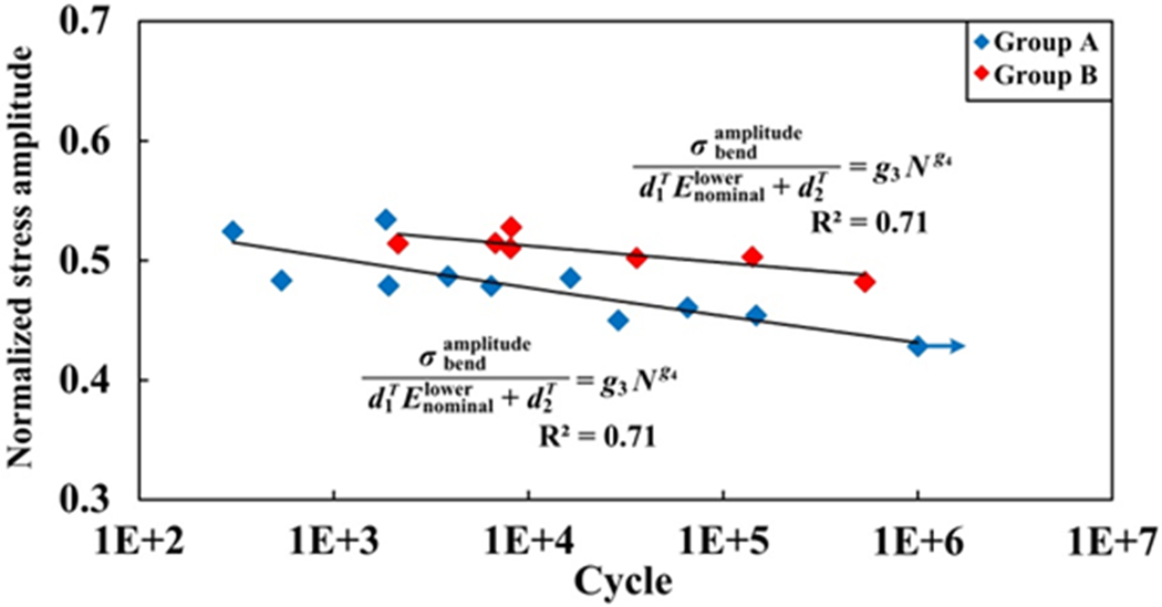
Normalized S-N data of SMC composites under bending fatigue loading considering the material heterogeneity of two opposing sides. The blue points are the experimental results in group A (ξ < 0.5). The red points are the experimental data in group B (ξ ≥ 0.5).
It is important to mention that component a11 in fiber orientation tensor [68] has been introduced in the fatigue modeling of SMC composites, which characterizes the alignment of carbon fiber chips. The correlation between a11 and modulus has also been studied in our previous work [37, 47, 48]. Then, the normalized bending fatigue models of SMC composites also can be transformed to fiber orientation-based forms. In real-world applications, the fiber orientation tensor of SMC components can be obtained by simulation software of manufacturing process, e.g., CoreTech Moldex3D and Autodesk Moldflow. Accordingly, the bending fatigue behavior of SMC components can be predicted based on the results from the present work.
The failure mechanism is further explored to better understand the bending fatigue behavior of SMC composites and the reason for enhanced fatigue life with a higher nominal modulus at the upper side. First, the interrupted tests are designed based on the proposed normalized bending fatigue model given in Eq. (4). The bending fatigue tests are suspended at the early stage of the fatigue failure procedure (approximately 10% of the predicted bending fatigue life). Small macro-scale cracks already exist at the lower side for all interrupted specimens, and one typical case is shown in Fig. 6. We can see that crack propagation plays a significant role in the bending fatigue failure of SMC composites as cracks appear at such early fatigue life. Moreover, we further examine the valid specimens after four-point bending fatigue tests. The final fractures at the lower side, upper side, and edge of a representative specimen are given in Fig. 7(a)-(c). In addition to the obvious cracks at the lower side, visible macro-cracks also can be found at the upper side. From the edge, delamination is distinct from the lower side to the layers which are close to the upper side. The fractures of SMC composites under bending fatigue loading indicate that the specimens can still bear the cyclic load while the bottom layers are experiencing breakage. Under this condition, the material property of the upper side also becomes important to the bending fatigue failure of SMC composites, which is consistent with the bending fatigue performance plotted in Fig. 5. It is important to point out that the failure modes of SMC composites under uniaxial fatigue loadings with different stress ratios are similar, which include chip splitting failure, matrix failure, and interface failure [37, 50]. Theoretically, the stress states at the lower and upper sides are close to that under uniaxial tension-tension and compression-compression fatigue loadings, respectively. As a result, the failure modes of SMC composites under bending fatigue loading should be very similar to those under uniaxial fatigue loadings.
Fig. 6.
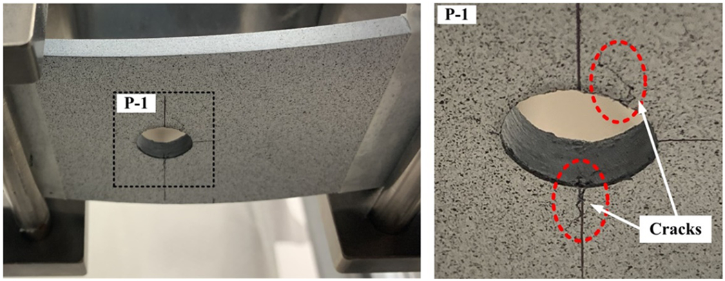
Obvious cracks form at the lower side of a typical interrupted specimen (~10% of the predicted bending fatigue life). Observable macro-scale cracks are marked by red ellipses.
Fig. 7.
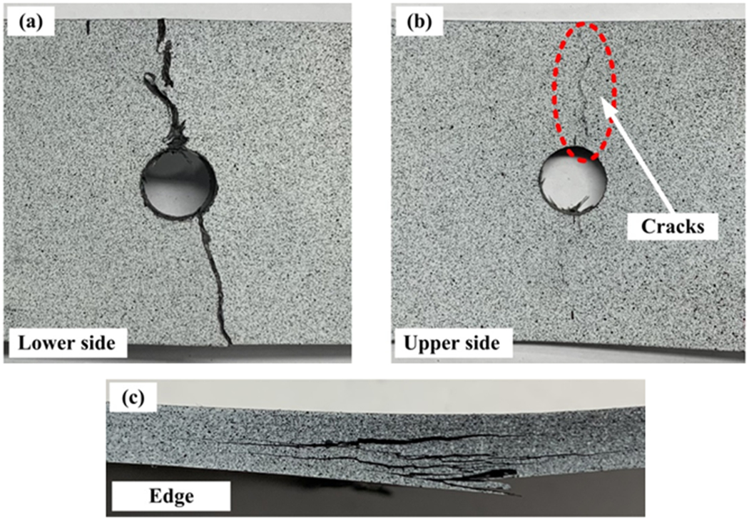
Fractures of a representative specimen after cyclic bending at (a) the lower side, (b) the upper side, and (c) the edge.
4. Fatigue Simulation for SMC Composites under Four-Point Bending
4.1. A hybrid micro-macro computational model for bending simulation
In order to accurately and efficiently simulate the bending fatigue behavior of SMC composites, a hybrid micro-macro computational model is established in this subsection. The modified RSA algorithm (Fig. 8) proposed in our previous work [49] is adopted to reconstruct the microstructure at the region of interest. The dimensions of the carbon fiber chip are 15~25 mm × 2~5 mm × 0.1 mm, and the chip volume fraction in SMC composites is approximately 80% [50]. Since the theoretical stress states at different layers vary through the thickness direction, the thickness of the computational model should be the same as that of the specimen, which is 4.8 mm. Then, the corresponding layer number at the region of interest generated by the modified RSA algorithm is 48, given the mean thickness of each layer is 0.1 mm. As introduced in the modified RSA algorithm, the second-order fiber orientation tensor aij is adopted to describe the fiber orientation distribution [68]:
| (6) |
Fig. 8.
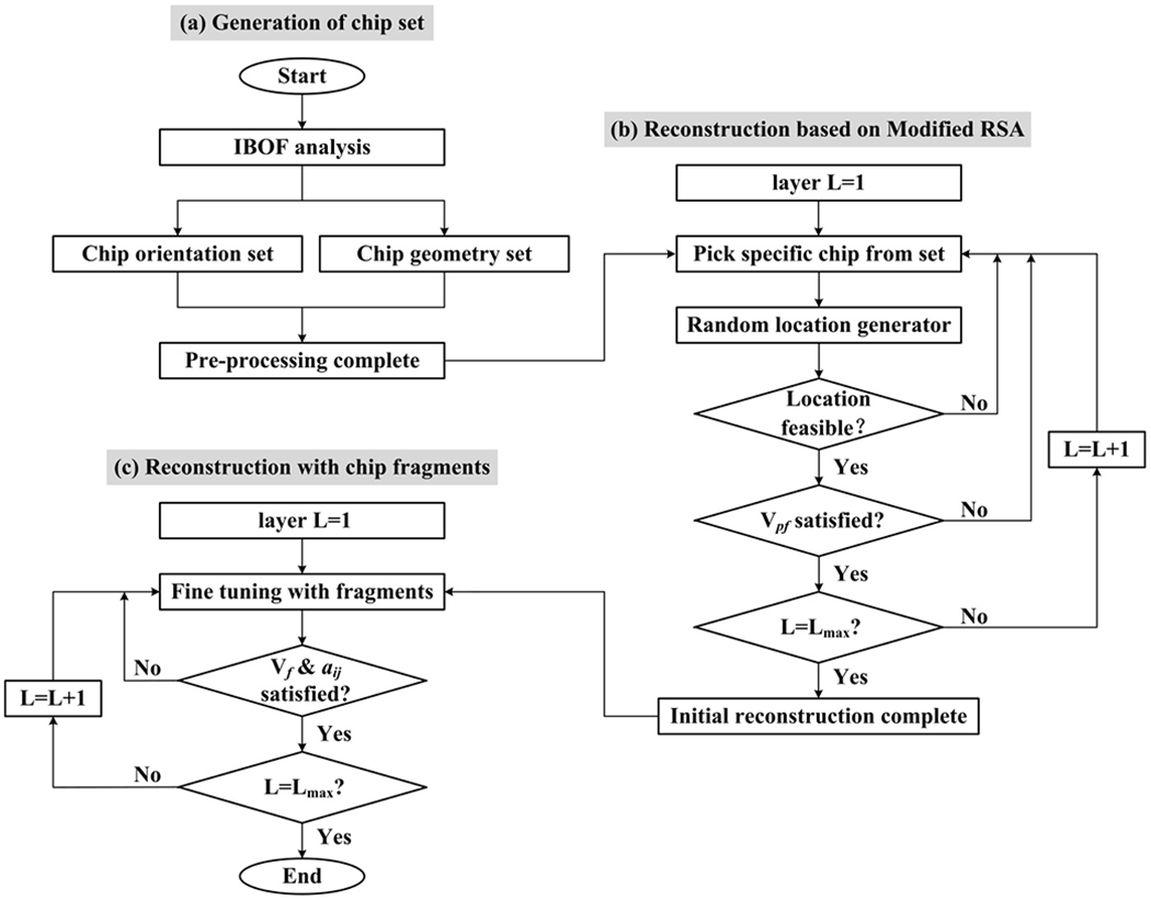
Flow chart of the modified RSA algorithm [49] for (a) generation of chip set, (b) reconstruction based on modified RSA algorithm, and (c) reconstruction with chip fragments.
where Φ is the fiber angle in the Cartesian coordinate system; is the probability distribution function. Note that the measured for SMC composites used in the bending fatigue tests ranges from 19.3 GPa to 27.2 GPa. Correspondingly, the main component a11 in the tensor is designed from 0.3 to 0.5 for layers from the bottom to the center, which gives rise to the range of local modulus from 18.1 GPa to 30.7 GPa (the relationship between modulus and a11 has been given in Ref. [37]). To simulate the bending fatigue behavior of SMC composites without a large discrepancy between the lower and upper side, first, a11 of layers from the center to the top is set as the same as that from the bottom to the center in each case. Second, to study the effect of the discrepancy between the lower and upper side on the bending fatigue performance of SMC composites, a11 = 0.5 is used to build up layers from the center to the top at the region of interest, while a11 = 0.3 is applied for layers from the bottom to the center (ξ = 0.7).
Other regions of SMC composites in the computational model are modeled as homogenized continua. One representative computational model for four-point bending fatigue simulation is shown in Fig. 9. The dimensions of the region of interest (the micro-scale model) are 25.4 mm × 25.4 mm × 4.8 mm. The different colored stripes involved in the micro-scale model represent the chopped carbon fiber chips, while the white areas refer to the vinyl ester matrix. Zero-thickness cohesive elements have also been introduced to describe the interfaces between chips and those between chip and matrix in the micro-scale model. In the hybrid micro-macro computational model, the gray beams connected to the micro-scale model are the homogenized regions of SMC composites. The length of the full SMC bending model should be longer than the support span, which is set as 175 mm. The radius of the steel pins is 5 mm, which is consistent with that in the bending fixture. The loading and support spans are 65 mm and 125 mm, respectively. It should be mentioned that the theoretical stress distribution between two loading pins is uniform. By adjusting the applied total force following Eq. (2), the shorter loading and support spans have limited influence on the numerical simulation. In addition, as the notch-insensitivity of SMC composites has been proved in Ref. [50, 64, 65], we use the specimens with a circular hole to improve the proportion of valid data. In contrast, it is not necessary to introduce the circular hole in the computational model as the failure at the loading region can be prohibited in numerical simulations. So, we just use the regular reconstruction model for the region of interest.
Fig. 9.
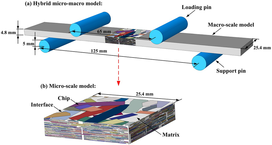
A hybrid micro-macro computational model for four-point bending fatigue simulation with magnified micro-scale model shown in (b). In the micro-scale model, different color strands represent different chips. The white regions are matrix. Zero-thickness cohesive elements have been introduced between chips and between chip and matrix.
In the finite element analysis, first-order tetrahedral element (C3D4), wedge element (C3D6), and reduced-order hexahedral element (C3D8R) are adopted for the carbon fiber chips, vinyl ester matrix, homogenized regions as well as the steel pins, while 6-node cohesive element (COH3D6) and 8-node cohesive element (COH3D8) are used to represent the interfaces. The chips are treated as transversely isotropic, and the resin matrix is assumed to be isotropic. The elastic properties of chip, vinyl ester resin, interface, homogenized region, and steel pin are listed in Table 1 [47, 50, 69, 70]. The material properties of the carbon fiber chip [47] have been calculated and validated by an RVE model of unidirectional composites [71]. Since the SMC composites used in the present study are globally isotropic, the elastic property of SMC composites with a11 = 0.5 is used for the homogenized regions. During the bending simulation, the support pins are fixed. The loading pins are coupled to a reference node, and a concentrated force perpendicular to the SMC bending model is applied to the reference node.
Table 1.
Elastic properties of chip, resin, interface, homogenized region, and steel pin.
| Chip | Matrix | Homogenized region | |||
|---|---|---|---|---|---|
|
| |||||
| E11 (GPa) | 125.9 | E (GPa) | 3.3 | E (GPa) | 30.7 |
| E22 (GPa) | 8.6 | v | 0.38 | v | 0.32 |
|
|
|||||
| G12 (GPa) | 4.8 | Interface | Steel pins | ||
|
|
|||||
| v 12 | 0.32 | K (GPa/mm) | 30 | E (GPa) | 190 |
| v 23 | 0.61 | v | 0.265 | ||
4.2. Progressive fatigue damage under cyclic bending
The framework of the progressive fatigue damage for SMC composites has been developed in our previous work [50], in which the fatigue failure of each element is independent and controlled by the corresponding continuum damage model. The flowchart for SMC composites under four-point bending fatigue loading is also similar to our previous efforts in modeling fatigue SMC composites under in-plane loadings, as given in Fig. 10. The explicit analysis in Abaqus is performed for the hybrid micro-macro computational model step-by-step. Nevertheless, only the stress states of elements in the region of interest are extracted to calculate the damage accumulation. The continuum damage models and the corresponding inputs of each phase at the region of interest, i.e., chip, resin, and interface, have been introduced in Ref. [50], while the synopsis of the damage models and the corresponding inputs is shown in Fig. 10. The continuum damage models of the chip, resin, and interface are proposed as a power law function of the local stress, following the works in Ref. [72–74]. The material parameters in the continuum damage models are calculated by the corresponding fatigue data. The progressive fatigue damage simulation is performed step-by-step. In each step, the stress distribution is re-simulated in Abaqus. The damage accumulation of each element is then calculated according to the designed cycle increment procedure. The failed elements would be deleted after that. It should be mentioned that a simplified cycle increment procedure is adopted at the stage ‘update cycle & delete elements’ (as shown in Fig. 10) to reduce the computational cost in the bending fatigue simulation. In general, the designed cycle increment procedure would have some influence on the predicted results. Thus, the value of interface strength is recalibrated based on SMC bending fatigue results.
Fig. 10.
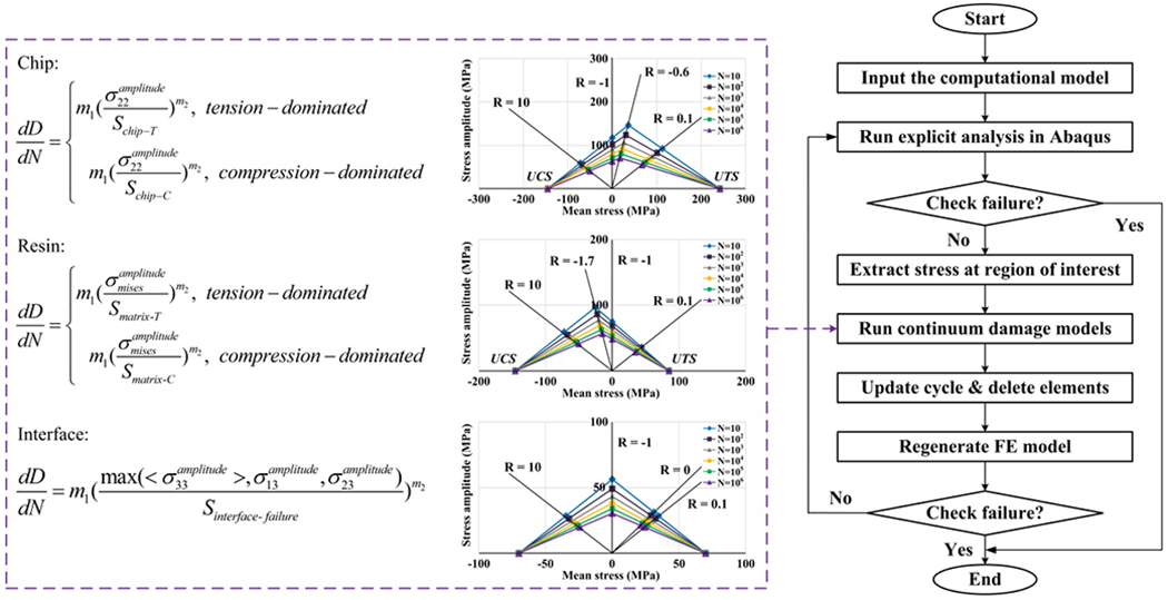
The flowchart of simulating progressive fatigue damage under cyclic bending [50].
4.3. Simulation results of SMC composites under bending fatigue loading
The generated hybrid micro-macro computational models are employed to evaluate the effect of fiber orientation distribution on the SMC bending fatigue performance in this section. The configuration for cyclic bending is the same for all cases. First, the loading level is set the same for cases with a11 = 0.3, 0.4, and 0.5. Further, to validate the effect of the discrepancy between the lower and upper sides on high cycle fatigue of SMC composites, another loading level is set for cases with the same lower side but different upper sides. Details are summarized in Table 2. We note that the reliability of the reconstruction model for the region of interest has been tested in our previous works [49, 50].
Table 2.
The loading level in bending fatigue simulation.
| Case | a11 (bottom to center) | a11 (center to top) | Maximum F (N) | (MPa) |
|---|---|---|---|---|
| #1 | 0.3 | 0.3 | 1600 | 113 |
| #2 | 0.4 | 0.4 | 1600 | 113 |
| #3 | 0.5 | 0.5 | 1600 | 113 |
| #4 | 0.3 | 0.3 | 1350 | 95 |
| #5 | 0.3 | 0.5 | 1350 | 95 |
The moduli of SMC composites with different a11 have been given in Ref. [37]. Then, the normalized stress amplitude for the computational models can be calculated based on Eq. (4). The predicted bending fatigue results of the reconstructed computational models are plotted in Fig. 11 together with the experimental data for comparison. While the applied load in Case #1, #2, and #3 is the same, the predicted bending fatigue life increases with the increment of the a11, which is consistent with the experimental data. Moreover, while the a11 of the lower side keeps constant, the predicted bending fatigue life becomes longer for computational models with a higher a11 at the upper side. This corroborates our experimental finding that the material property of the upper side is also influential to the bending fatigue failure of SMC composites. It can be found that the effect of the heterogeneous fiber orientation distribution on the bending fatigue behavior can be well reproduced by combining the hybrid micro-macro computational model and the framework of progressive fatigue damage for cyclic bending.
Fig. 11.
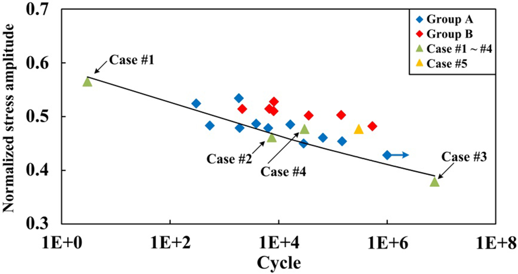
The predicted bending fatigue results with the reconstructed computational models. The blue points are the experimental results in group A (ξ < 0.5). The red points are the experimental data in group B (ξ ≥ 0.5). The green points are the simulation results for Case #1 ~ #4, of which the fiber orientation distribution is the same for two opposing sides (ξ = 0). The yellow point is the simulation data of Case #5 (ξ = 0.7).
The bending fatigue failure processes of a typical hybrid micro-macro computational model (Case #2 in Table 2) are shown in Fig. 12. At the early stage of the fatigue failure procedure, cracks are observed at the region of interest, and delamination can be found at the lower side. In addition, chip splitting failure, matrix failure, and interface failure can be well reproduced in bending fatigue prediction. The delamination is obvious from the edge of the region of interest when the computational model is broken. Therefore, the hybrid computational model constructed in this study can accurately predict the S-N diagrams of SMC composites under bending fatigue loading, and also capture the realistic bending fatigue failure behavior.
Fig. 12.
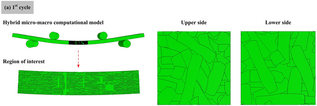
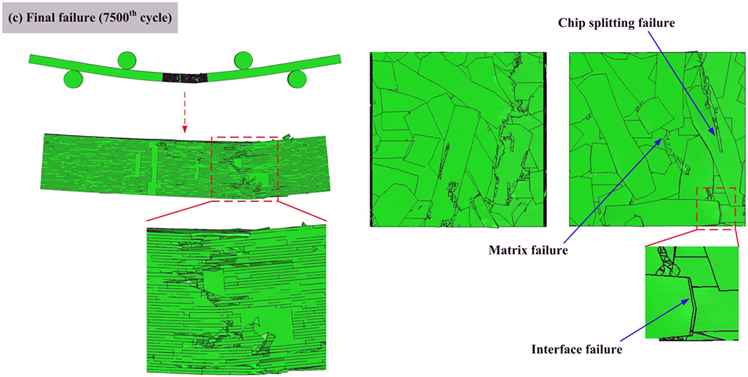
Bending fatigue failure processes of a typical computational model (Case #2), at (a) 1st cycle, (b) 500th cycle, and (c) final failure (7500th cycle).
5. Closing remarks
5.1. Discussions
As illustrated in our previous investigation on the structure-property relationship of SMC composites [36, 37], the variations of local chip volume fraction, especially in the resin-rich regions, influence the measured local modulus and material performance. Since the chip volume fraction of SMC composites used in the present study reaches approximately 80% and the variation of local chip volume fraction is not remarkable, the fiber orientation plays the most dominant role in the bending fatigue of SMC composites. However, the effects of local chip volume fraction and local fiber orientation should be both considered when SMC composites with low chip volume fraction are adopted in real-world applications.
In the designed experiments, we choose the side with the relatively lower nominal modulus as the lower side, i.e., the tension-dominated side. We note that the stress states of the lower and upper sides are close to that under uniaxial tension-tension and compression-compression fatigue loading, respectively. For materials with low modulus, i.e., a11 is small, the compression-compression fatigue strength of SMC composites is higher than the tension-tension fatigue strength [37]. Then, in engineering application, though low modulus would occur at both sides, the tension-dominate side would still fail earlier. Hence, the fatigue model proposed in the present study is suited for the majority of cases.
5.2. Conclusions
In this paper, we have investigated the bending fatigue behavior of SMC composites utilizing both experimental and numerical methods. We have carried out the four-point bending fatigue tests for SMC composites, and adopted the local modulus as a metric to represent the local fiber orientation of two opposing sides. We find that the local microstructures of both sides influence bending fatigue performance. While it is straightforward that higher local modulus at the lower side increases the fatigue life as bending fatigue failure of SMC composites is tension-dominated, it is more interesting to see that higher modulus at the upper side gives rise to longer fatigue life, which becomes more remarkable for high cycle fatigue cases. This observation promotes us to categorize the bending fatigue results for SMC composites by whether there is a large discrepancy between two opposing sides or not. With consideration of this heterogeneous local fiber orientation distribution at both sides, more accurate bending fatigue models can be developed. Meanwhile, we perform the interrupted tests to explore the bending fatigue failure mechanism, and also examine the damage processes of valid specimens after four-point bending fatigue tests. It is found that the bending fatigue failure of SMC composites is dominated by crack propagation instead of crack initiation, and this is the reason that the local structural features and mechanical properties of the upper side is also influential to the bending fatigue failure of SMC composites. Furthermore, a hybrid micro-macro computational model is proposed to simulate the cyclic bending behavior of SMC composites. The region of interest, having all the microstructural details, is reconstructed with a modified RSA algorithm in which the fiber orientation tensor is used to characterize the fiber orientation distribution, while other regions are modeled as homogenized continua. The developed computational model has been shown to accurately predict the S-N diagrams of SMC composites under bending fatigue loading and capture the realistic failure behavior of bending fatigue. The integrated computational and experimental efforts presented here provide important insights into the fatigue behaviors of SMC composites under cyclic bending and their dependence on the internal structures of the composites.
Acknowledgments
This research is supported by Ford Motor Company with funding from the U.S. Department of Energy’s Office of Energy Efficiency and Renewable Energy (EERE) under Award Number DE-EE0006867. Z. Meng would like to acknowledge startup funds from Clemson University and SC TRIMH support (P20 GM121342). The authors also gratefully acknowledge the contribution of Mr. Ziang Li and Dr. Yang Li from Ford Motor Company for the assistance of the four-point bending fatigue test setup and the detailed discussion of the bending fatigue simulation.
Appendix A. Details of the valid experimental results of SMC composites under cyclic four-point bending
| Specimen | (GPa) | (GPa) | ξ | (MPa) | Cycle |
|---|---|---|---|---|---|
| B-1 | 27.2 | 38.4 | 0.41 | 121 | 28956 |
| B-2 | 24.4 | 28.2 | 0.16 | 113 | 148269 |
| B-3 | 24.2 | 27.2 | 0.12 | 106 | 1003000 (run out) |
| B-4 | 24.5 | 30.5 | 0.24 | 119 | 6457 |
| B-5 | 20.8 | 30.5 | 0.47 | 101 | 65708 |
| B-6 | 21.1 | 28.8 | 0.36 | 119 | 1854 |
| B-7 | 23.7 | 32.4 | 0.37 | 127 | 303 |
| B-8 | 25.5 | 29.7 | 0.16 | 125 | 3860 |
| B-9 | 20.8 | 23.9 | 0.15 | 106 | 540 |
| B-10 | 22.4 | 30.1 | 0.34 | 113 | 16491 |
| B-11 | 24.3 | 33.6 | 0.38 | 119 | 1919 |
| B-12 | 22.2 | 38.4 | 0.73 | 118 | 8115 |
| B-13 | 25.7 | 42.4 | 0.65 | 125 | 535295 |
| B-14 | 21.1 | 36.3 | 0.72 | 117 | 8186 |
| B-15 | 24.1 | 37.1 | 0.54 | 123 | 35989 |
| B-16 | 19.4 | 30.3 | 0.56 | 108 | 6758 |
| B-17 | 24.1 | 36.2 | 0.50 | 124 | 141682 |
| B-18 | 19.3 | 33.8 | 0.75 | 107 | 2143 |
Reference
- [1].Kawai M, Koizumi M. Nonlinear constant fatigue life diagrams for carbon/epoxy laminates at room temperature. Composites Part A: Applied Science and Manufacturing. 2007; 38: 2342–2353. [Google Scholar]
- [2].Naya F, Herráez M, Lopes CS, González C, Van der Veen S, Pons F. Computational micromechanics of fiber kinking in unidirectional FRP under different environmental conditions. Composites Science and Technology. 2017; 144: 26–35. [Google Scholar]
- [3].Sun Q, Zhou G, Tang H, Chen Z, Fenner J, Meng Z, Jain M, Su X. A combined experimental and computational analysis of failure mechanisms in open-hole cross-ply laminates under flexural loading. Composites Part B: Engineering. 2021; 215: 108803. [DOI] [PMC free article] [PubMed] [Google Scholar]
- [4].Yao SS, Jin FL, Rhee KY, Hui D, Park SJ. Recent advances in carbon-fiber-reinforced thermoplastic composites: a review. Composites Part B: Engineering. 2018; 142: 241–250. [Google Scholar]
- [5].Tang H, Sun Q, Li Z, Su X, Yan W. Longitudinal compression failure of 3D printed continuous carbon fiber reinforced composites: An experimental and computational study. Composites Part A: Applied Science and Manufacturing. 2021; 146: 106416. [Google Scholar]
- [6].Shabani P, Taheri-Behrooz F, Samareh-Mousavi SS, Shokrieh MM. Very high cycle and gigacycle fatigue of fiber-reinforced composites: A review on experimental approaches and fatigue damage mechanisms. Progress in Materials Science. 2021; 118: 100762. [Google Scholar]
- [7].Shabani P, Taheri-Behrooz F, Maleki S, Hasheminasab M. Life prediction of a notched composite ring using progressive fatigue damage models. Composites Part B: Engineering. 2019; 165: 754–763. [Google Scholar]
- [8].Samareh-Mousavi SS, Mandegarian S, Taheri-Behrooz F. A nonlinear FE analysis to model progressive fatigue damage of cross-ply laminates under pin-loaded conditions. International Journal of Fatigue. 2019; 119: 290–301. [Google Scholar]
- [9].Mandegarian S, Taheri-Behrooz F. A general energy based fatigue failure criterion for the carbon epoxy composites. Composite Structures. 2020; 235: 111804. [Google Scholar]
- [10].Wu L, Zhang F, Sun B, Gu B. Finite element analyses on three-point low-cyclic bending fatigue of 3-D braided composite materials at microstructure level. International Journal of Mechanical Sciences. 2014; 84: 41–53. [Google Scholar]
- [11].Wang L, Zhao B, Wu J. C. Chen, K. Zhou. Experimental and numerical investigation on mechanical behaviors of woven fabric composites under off-axial loading. International Journal of Mechanical Sciences. 2018; 141: 157–167. [Google Scholar]
- [12].Liang B, Zhang W, Fenner JS, Gao J, Shi Y, Zeng D, Su X, Liu WK, Cao J. Multi-scale modeling of mechanical behavior of cured woven textile composites accounting for the influence of yarn angle variation. Composites Part A: Applied Science and Manufacturing. 2019; 124: 105460. [Google Scholar]
- [13].Zhou G, Tang H, Sun Q, Li D, Peng Y, Zeng D, Su X. Analysis of the crushing behaviors of woven carbon fiber reinforced plastic hat section component under dynamic bending and axial crushing loading. Thin-Walled Structures. 2021; 161: 107426. [Google Scholar]
- [14].Taheri-Behrooz F, Bakhshan H. Characteristic length determination of notched woven composites. Advanced Composite Materials. 2018; 27: 67–83. [Google Scholar]
- [15].Hanhan I, Agyei R, Xiao X, Sangid MD. Comparing non-destructive 3D X-ray computed tomography with destructive optical microscopy for microstructural characterization of fiber reinforced composites. Composites Science and Technology. 2019; 184: 107843. [Google Scholar]
- [16].Wang K, Pei S, Li Y, Li J, Zeng D, Su X, Xiao X. N. Chen. In-situ 3D fracture propagation of short carbon fiber reinforced polymer composites. Composites Science and Technology. 2019; 182: 107788. [Google Scholar]
- [17].Huang ZM, Zhang CC, Xue YD. Stiffness prediction of short fiber reinforced composites. International Journal of Mechanical Sciences. 2019; 161–162: 105068. [Google Scholar]
- [18].Zeng H, Leng J, Gu J, Sun H. Modeling the thermomechanical behaviors of short fiber reinforced shape memory polymer composites. International Journal of Mechanical Sciences. 2020; 166: 105212. [Google Scholar]
- [19].Tang H, Chen H, Sun Q, Chen Z, Yan W. Experimental and computational analysis of structure-property relationship in carbon fiber reinforced polymer composites fabricated by selective laser sintering. Composites Part B: Engineering. 2021; 204: 108499. [Google Scholar]
- [20].Shokrieh MM, Esmkhani M, Taheri-Behrooz F, Haghihatkhah AR. Displacement controlled flexural bending fatigue behavior of graphene/epoxy nanocomposites. Journal of composite materials. 2014; 48: 2935–2944. [Google Scholar]
- [21].Feraboli P, Peitso E, Cleveland T. Modulus measurement for prepreg-based discontinuous carbon fiber/epoxy systems. Journal of Composite Materials. 2009; 43: 1947–1965. [Google Scholar]
- [22].Evans AD, Qian CC, Turner TA, Harper LT, Warrior NA. Flow characteristics of carbon fibre moulding compounds. Composites Part A: Applied Science and Manufacturing. 2016; 90: 1–12. [Google Scholar]
- [23].Favaloro AJ, Sommer DE. On the use of orientation tensors to represent prepreg platelet orientation state and variability. Journal of Rheology. 2020; 64: 517. [Google Scholar]
- [24].Shokrieh MM, Esmkhani M, Taheri-Behrooz F. Fatigue modeling of chopped strand mat/epoxy composites. Structural Engineering and Mechanics. 2014; 50: 231–240. [Google Scholar]
- [25].Turner MA, Alarcon AG, Bugaj SL, Levasseur G. Compressed chopped fiber composite structural guide vane. Google Patents. 2014. [Google Scholar]
- [26].Malnati P. Carbon fiber/epoxy for automotive mass reduction, mass production. Composites World. 2019. [Google Scholar]
- [27].Feraboli P, Peitso E, Deleo L, Cleveland T. Characterization of prepreg-based discontinuous carbon fiber/epoxy systems. Journal of Reinforced Plastics and Composites. 2009; 28: 1191–1214. [Google Scholar]
- [28].Febraboli P, Cleveland T, Ciccu M, Stickler P, Deoto L. Defect and damage analysis of advanced discontinuous carbon/epoxy composite materials. Composites Part A: Applied Science and Manufacturing. 2010; 41: 888–901. [Google Scholar]
- [29].Febraboli P, Cleveland T, Stickler P, Halpin J. Stochastic laminate analogy for simulating the variability in modulus of discontinuous composite materials. Composites Part A: Applied Science and Manufacturing. 2010; 41: 557–570. [Google Scholar]
- [30].Selezneva M, Lessard L. Characterization of mechanical properties of randomly oriented strand thermoplastic composites. Journal of Composite Materials. 2016; 50: 2833–2851. [Google Scholar]
- [31].Selezneva M, Roy S, Lessard L, Yousefpour A. Analytical model for prediction of strength and fracture paths characteristic to randomly oriented strand (ROS) composites. Composites Part B: Engineering. 2016; 96: 103–111. [Google Scholar]
- [32].Selezneva M, Roy S, Meldrum S, Lessard L, Yousefpour A. Modelling of mechanical properties of randomly oriented strand thermoplastic composites. Journal of Composite Materials. 2016; 0: 1–15. [Google Scholar]
- [33].Wan Y, Straumit I, Takahashi J, Lomov SV. Micro-CT analysis of internal geometry of chopped carbon fiber tapes reinforced thermoplastics. Composites Part A: Applied Science and Manufacturing. 2016; 91: 211–221. [Google Scholar]
- [34].Wan Y, Takahashi J. Tensile and compressive properties of chopped carbon fiber tapes reinforced thermoplastics with different fiber lengths and molding pressures. Composites Part A: Applied Science and Manufacturing. 2016; 87: 271–281. [Google Scholar]
- [35].Johanson K, Harper LT, Johnson MS, Warrior NA. Heterogeneity of discontinuous carbon fibre composites: damageinitiation captured by digital image correlation. Composites Part A: Applied Science and Manufacturing. 2015; 68: 304–312. [Google Scholar]
- [36].Tang H, Chen Z, Zhou G, Li Y, Avery K, Guo H, Kang H, Zeng D, Su X. Correlation between failure and local material property in chopped carbon fiber chip-reinforced sheet molding compound composites under tensile load. Polymer Composites. 2019; 40: E962–E974. [Google Scholar]
- [37].Tang H, Chen Z, Zhou G, Sun X, Li Y, Huang L, Guo H, Kang H, Zeng D, Engler-Pinto C, Su X. Effect of fiber orientation distribution on constant fatigue life diagram of chopped carbon fiber chip-reinforced sheet molding compound (SMC) composite. International Journal of Fatigue. 2019; 125: 394–405. [Google Scholar]
- [38].Nony-Davadie C, Peltier L, Chemisky Y, Surowiec B, Meraghni F. Mechanical characterization of anisotropy on a carbon fiber sheet molding compound composite under quasi-static and fatigue loading. Journal of Composite Materials. 2019; 53: 1437–1457. [Google Scholar]
- [39].Martulli LM, Muyshondt L, Kerschbaum M, Pimenta S, Lomov SV, Swolfs Y. Carbon fibre sheet moulding compounds with high in-mould flow: linking morphology to tensile and compressive properties. Composites Part A: Applied Science and Manufacturing. 2019; 105600. [Google Scholar]
- [40].Martulli LM, Muyshondt L, Kerschbaum M, Pimenta S, Lomov SV, Swolfs Y. Morphology-induced fatigue crack arresting in carbon fibre sheet moulding compounds. International Journal of Fatigue. 2020; 134: 105520. [Google Scholar]
- [41].Martulli LM, Kerschbaum M, Lomov S, Swolfs Y. Weld lines in tow-based sheet moulding compounds tensile properties: morphological detrimental factors. Composites Part A: Applied Science and Manufacturing. 2020; 139: 106109. [Google Scholar]
- [42].Martulli LM, Creemers T, Schoberl E, Hale N, Kerschbaum M, Lomov SV, Swolfs Y. A thick-walled sheet moulding compound automotive component: manufacturing and performance. Composites Part A: Applied Science and Manufacturing. 2020; 128: 105688. [Google Scholar]
- [43].Alves M, Carlstedt D, Ohlsson F, Asp LE, Pimenta S. Ultra-strong and stiff randomly-oriented discontinuous composites: Closing the gap to quasi-isotropic continuous-fibre laminates. Composites Part A: Applied Science and Manufacturing. 2020; 132: 105826. [Google Scholar]
- [44].Alves M, Pimenta S. The influence of 3D microstructural features on the elastic behaviour of Tow-Based Discontinuous Composites. Composite Structures. 2020; 251: 112484. [Google Scholar]
- [45].Li Y, Pimenta S. Development and assessment of modelling strategies to predict failure in tow-based discontinuous composites. Composite Structures. 2019; 209: 1005–1021. [Google Scholar]
- [46].Harper LT, Qian CC, Luchoo R, Warrior NA. 3D geometric modelling of discontinuous fibre composites using a force-directed algorithm. Journal of Composite Materials. 2017; 51: 2389–2406. [Google Scholar]
- [47].Li Y, Chen Z, Su L, Chen W, Jin X, Xu H. Stochastic reconstruction and microstructure modeling of SMC chopped fiber composites. Composite Structures. 2018; 200: 153–164. [Google Scholar]
- [48].Chen Z, Huang T, Shao Y, Li Y, Xu H, Avery K, Zeng D, Chen W, Su X. Multiscale finite element modeling of sheet molding compound (SMC) composite structure based on stochastic mesostructure reconstruction. Composite Structures. 2018; 188: 25–38. [Google Scholar]
- [49].Tang H, Zhou G, Chen Z, Huang L, Avery K, Li Y, Liu H, Guo H, Kang H, Zeng D, Engler-Pinto C, Su X. Fatigue behavior analysis and multi-scale modelling of chopped carbon fiber chip-reinforced composites under tension-tension loading condition. Composite Structures. 2019; 215: 85–97. [Google Scholar]
- [50].Tang H, Chen Z, Avinesh O, Guo H, Meng Z, Engler-Pinto C, Kang H, Su X. Notch insensitivity in fatigue failure of chopped carbon fiber chip-reinforced composites using experimental and computational analysis. Composite Structures. 2020; 244: 112280. [DOI] [PMC free article] [PubMed] [Google Scholar]
- [51].Chen Z, Tang H, Shao Y, Sun Q, Zhou G, Li Y, Xu H, Zeng D, Su X. Failure of chopped carbon fiber sheet molding compound (SMC) composites under uniaxial tensile loading: computational prediction and experimental analysis. Composites Part A: Applied Science and Manufacturing. 2019; 118: 117–130. [Google Scholar]
- [52].Tang H, Chen Z, Xu H, Zhao L, Sun Q, Zhou G, Yan W, Han W, Su X. Computational micromechanics model based failure criteria for chopped carbon fiber sheet molding compound composites. Composites Science and Technology. 2020; 200: 108400. [Google Scholar]
- [53].Sommer DE, Favaloro AJ, Pipes RB. Coupling anisotropic viscosity and fiber orientation in applications to squeeze flow. Journal of Rheology. 2018; 62: 669. [Google Scholar]
- [54].Sommer DE, Kravchenko SG, Denos BR, Favaloro AJ, Pipes RB. Integrative analysis for prediction of process-induced, orientation dependent tensile properties in a stochastic prepreg platelet molded composite. Composites Part A: Applied Science and Manufacturing. 2020; 130: 105759. [Google Scholar]
- [55].Sommer DE, Kravchenko SG, Pipes RB. A numerical study of the meso-structure variability in the compaction process of prepreg platelet molded composites. Composites Part A: Applied Science and Manufacturing. 2020; 138: 106010. [Google Scholar]
- [56].Kravchenko SG, Sommer DE, Denos BR, Favaloro AJ, Tow CM, Avery WB, Pipes RB. Tensile properties of a stochastic prepreg platelet molded composite. Composites Part A: Applied Science and Manufacturing. 2019; 124: 105507. [Google Scholar]
- [57].Kravchenko SG, Sommer DE, Denos BR, Avery WB, Pipes RB. Structure-property relationship for a prepreg platelet molded composite with engineered meso-morphology. Composite Structures. 2019; 210: 430–445. [Google Scholar]
- [58].Thama J, Sabistona T, Trauthb A, Lévesquec J, Weidenmannb KA, Inal K. The effect of tension compression asymmetry on modelling the bending response of sheet moulding compound composites. Composites Part B: Engineering. 2018; 154: 157–165. [Google Scholar]
- [59].Sabiston T, Pinter P, Lee-Sullivan P, Inal K. Prediction of bending in SMC using a single parameter damage model that accounts for through thickness microstructural properties. Composite Structures. 2020; 246: 112377. [Google Scholar]
- [60].Palmer J, Savage L, Ghita OR, Evans KE. Sheet moulding compound (SMC) from carbon fibre recyclate. Composites Part A: Applied Science and Manufacturing. 2010; 41: 1232–1237. [Google Scholar]
- [61].Ogi K, Yamanouchi M. Temperature dependence of flexural strength of a CF-SMC composite. Applied Composite Materials. 2011; 18: 397–408. [Google Scholar]
- [62].Lee H, Huh M, Yoon J, Lee D, Kim S, Kang S. Fabrication of carbon fiber SMC composites with vinyl ester resin and effect of carbon fiber content on mechanical properties. Carbon Letters. 2017; 22: 101–104. [Google Scholar]
- [63].Ishikawa T, Amaoka K, Masubuchi Y, Uamamoto T, Yamanka A, Arai M, Takahashi J. Overview of automotive structural composites technology developments in Japan. Composites Science and Technology. 2018; 155: 221–246. [Google Scholar]
- [64].Feraboli P, Peitso E, Cleveland T, Stickler PB, Halpin JC. Notched behavior of prepreg-based discontinuous carbon fiber/epoxy systems. Composites Part A: Applied Science and Manufacturing. 2009; 40: 289–299. [Google Scholar]
- [65].Qian C, Harper LT, Turner TA, Warrior NA. Notched behaviour of discontinuous carbon fibre composites: Comparison with quasi-isotropic non-crimp fabric. Composites Part A: Applied Science and Manufacturing. 2011; 42: 293–302. [Google Scholar]
- [66].Polymer matrix composites materials usage, design, and analysis. Department of defense handbook-composite materials handbook. 2002; 3: 5–58. [Google Scholar]
- [67].Nijs A, Selezneva M, Swolfs Y, Hirano N, Taketa I, Karaki T, Verpoest I, Gorbatikh L. Notch-sensitivity of hybrid carbon-fibre/self-reinforced polypropylene composites. Composites Science and Technology. 2020; 200: 108422. [Google Scholar]
- [68].Advani SG, Tucker CL. The use of tensors to describe and predict fiber orientation in short fiber composites. Journal of Rheology. 1987; 31: 751–784. [Google Scholar]
- [69].DERAKANE® Epoxy Vinyl Ester Resins 411–350. 2004. [Google Scholar]
- [70].Technical Data Sheet Vinylester Infusion Resin. 2016. [Google Scholar]
- [71].Melro AR, Camanho PP, Pinho ST. Generation of random distribution of fibres in long-fibre reinforced composites. Composites Science and Technology. 2008; 68: 2092–2102. [Google Scholar]
- [72].Mao H, Mahadevan S. Fatigue damage modelling of composite materials. Composite Structures. 2002; 58: 405–410. [Google Scholar]
- [73].Shenoy V, Ashcroft LA, Critchlow GW, Crocombe AD. Unified methodology for the prediction of the fatigue behaviour of adhesively bonded joints. International Journal of Fatigue. 2010; 32: 1278–1288. [Google Scholar]
- [74].Solana AG, Crocombe AD, Ashcroft IA. Fatigue life and backface strain predictions in adhesively bonded joints. International Journal of Adhesion and Adhesives. 2010; 30: 36–42. [Google Scholar]


