Abstract
Objectives.
To understand the stress development in porcelain-veneered zirconia (PVZ) and porcelain-veneered lithium disilicate (PVLD) crowns with different veneer/core thickness ratios and cooling rates. To provide design guidelines for better performing bilayer restorations with the aid of Viscoelastic Finite Element Method (VFEM).
Methods.
The VFEM was validated by comparing the predicted residual stresses with experimental measurements. Then, the model was used to predict transient and residual stresses in the two bilayer systems. Models with two different veneer/core thickness ratios were prepared (2:1 and 1:1) and two cooling protocols were simulated (Fast: ~300°C/min, Slow: ~30°C/min) using the heat transfer module, followed by stress analysis in ABAQUS. The physical properties of zirconia, lithium disilicate, and the porcelains used for the simulations were determined as a function of temperature.
Results.
PVLD showed lower residual stresses than PVZ. The maximum tensile stresses in PVZ were observed in the cusp area, whereas those in PVLD were located in the central fossa. The 1:1 thickness ratio decreased stresses in both layers of PVZ. Slow cooling slightly decreased residual stresses in both systems. However, the cooling rate effect was more evident in transient stresses.
Significance.
Slow cooling is preferable for both systems. A thinner porcelain layer over zirconia lowers stresses throughout the restoration. The different stress distributions between PVZ and PVLD may affect their failure modes. Smaller mismatches in modulus, CTE, and specific heat between the constituents, and the use of low Tg porcelains can effectively reduce the deleterious transient and residual tensile stresses in bilayer restorations.
Keywords: dental ceramics, bilayer crowns, transient stress, residual stress, cooling rate, elastic modulus, coefficient of thermal expansion, specific heat
1. Introduction
Metal-free bilayer ceramic restorations have been popular over the last decades due to the great esthetics results combined with satisfying mechanical properties. The pressing technique for glass-ceramics and the Computer-Aided Design/Computer-Aided Manufacturing (CAD/CAM) technology for milling glass-ceramics or cutting polycrystalline zirconia have allowed the fabrication of strong frameworks [1] that, combined with a porcelain veneer layer, can reach the most esthetic results. In addition, owing to the strength required from a framework material, the most popular and reliable options for all-ceramic bilayer crowns are porcelain-veneered zirconia (PVZ) and porcelain-veneered lithium disilicate (PVLD).
Clinical studies have shown survival rates around 94% to 95% [2, 3] for PVZ in 5 years and the most common cause of complications reported is porcelain chipping. A 3-year follow-up retrospective study of PVZ single crowns reported 100% survival; however, 30% of the restorations needed clinical intervention (e.g. polishing) due to minor chipping of porcelain. [4] Sailer et al. [5] pointed out in a systematic review of clinical studies that bilayer crowns with zirconia frameworks have a high risk of veneer chipping along with loss of retention. On the other hand, the high strength of zirconia allows it to be indicated for a wide range of clinical applications.
Porcelain-veneered lithium disilicate crowns have shown survival rates up to 100% in 8 years [6] and 98% in 11 years. [7] Despite the high survival rates, previous studies have described chipping and bulk fracture as the main cause of failure of these restorations. Valenti and Valenti evaluated PVLD crowns for over 10 years (survival rate: 95.5%). [8] They observed that 66% of the failures were due to major chipping of the porcelain and 34% were due to bulk fracture. Similarly, Yang et al found that 60% of the failures in PVLD crowns were due to major chipping and 20% were bulk fracture among other technical complications after 5 years of follow-up (survival rate: 97%). [9]
Clinical failures in ceramic crowns can be originated from contact damage at the occlusal surface or from the cementation surface beneath the occlusal contact. [10] The most common clinical fracture modes in bilayer restorations are chipping, delamination, and bulk fracture, which are sketched in Figure 1. The clinical fractures can be induced by internal and surface flaws, stress-corrosion fatigue (slow crack growth), mechanical degradation, or a combination of factors that leads to stress concentration, [11, 12] such as restoration design, [13–15] inadequate firing, [16] coefficient of thermal expansion mismatch. [17, 18]
Figure1.
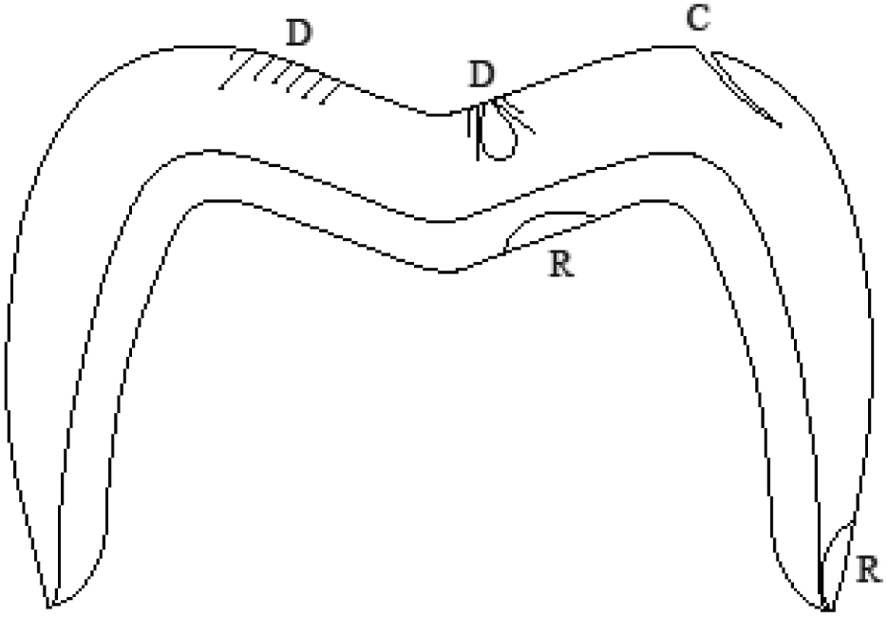
Schematic diagram depicting common fracture modes in bilayer crowns: D shows contact damage, that may propagate causing delamination or chipping, R depicts radial cracks, which lead to bulk fracture or marginal fracture, and C shows edge chipping, originated in the cusp area.
Residual stresses have been described as an important factor for increasing the susceptibility of the porcelain layer to fracture. Factors such as the cooling rate, [19–22] layer thickness ratio, [23] and framework material [19] have been demonstrated to influence the stress profile in bilayer systems. In dental literature, previous studies have demonstrated that the cooling rate actually affects more the transient than the residual stresses. [19, 23] Transient stresses may exceed the fracture strength of ceramics, which causes micro-crack formation and, consequently, increases the susceptibility of ceramic restorations to premature failure. Previous investigations have used different methods for measuring residual stresses, such as Vickers indentations, [24–27] birefringence, [28–30] and hole-drilling. [31] However, the aforementioned approaches cannot capture the entire stress history over time.
Despite the factors influencing the stresses in porcelain-veneered zirconia have been more extensively studied, there is a lack of information regarding porcelain-veneered lithium disilicate. It is still not clear if the magnitude and distribution of residual stresses can be associated with the aforementioned fracture rates of these materials. Accordingly, this study aimed to understand the stress development in bilayer metal free restorations comparing the use of a glass (lithium disilicate) and a polycrystalline (3Y-TZP) ceramic, as framework. We evaluated how the cooling rate (fast or slow), layer thickness ratio (2:1 or 1:1), and materials properties affect the stress development in both systems using a Viscoelastic Finite Element Method (VFEM). [23, 32, 33] An experimental validation was performed and the material properties used in the FEM model were measured as a function of the temperature to ensure the reliability of the results. The tested hypotheses were: 1) residual and transient stresses would develop differently for PVZ and PVLD, due to their different thermomechanical properties, and 2) slow cooling and 3) 1:1 thickness ratio would decrease the stresses in both bilayer systems, as pointed out in previous literature. [23] Finally, based on our findings, the key material properties as well as crown geometric and processing parameters responsible for the formation of the deleterious transient and residual tensile stresses in the bilayer systems have been identified.
2. Materials and Methods
2.1. Study Design
Two metal-free ceramic systems were selected for this study: lithium disilicate (e.max CAD MO, Ivoclar Vivadent, Schaan, Liechtenstein) as framework and a nanofluorapatite ceramic (e.max Ceram, Ivoclar Vivadent, Schaan, Liechtenstein) as veneer (PVLD), and a 3Y-TZP (Zpex, Tosoh, Tokyo, Japan) as framework and a feldspathic ceramic (Vita PM9, Vita Zahnfabrik, Bad Sackingen, Germany) as veneer (PVZ). The materials’ characteristics and properties at room temperature are described in Table 1. A Viscoelastic Finite Element Method (VFEM) was used to simulate two cooling rates (fast or slow) in symmetrical ¼ crown models with two thickness ratios (2:1 or 1:1) for each ceramic system (PVLD or PVZ) and evaluate the development of transient and residual stresses.
Table 1.
Materials’ characteristics and properties at room temperature
| Material (manufacturer) | Composition | Elastic modulus, E (GPa) | Density, ρ (g/cm3) | CTE (10−6K−1) | Poisson’s ratio, υ | Tg (°C) | Ts (°C) | Thermal conductivity (W/mmK) | Specific heat (J/kg K) |
|---|---|---|---|---|---|---|---|---|---|
| Emax Ceram (Ivoclar Vivadent) | Nanofluorapatite | 65 | 2.51 | 9.5 | 0.23 | 483 | 530 | 1.01e−3 | 846 |
| Emax CAD (Ivoclar Vivadent) | Lithium disilicate | 103 | 2.48 | 10.1 | 0.21 | 665 | 820 | 2.78e−3 | 852 |
| PM9 (Vita Zahnfabrik) | Feldspar | 60 | 2.40 | 9.5 | 0.21 | 644 | 684 | 1.11e−3 | 821 |
| Zpex (Tosoh) | 3Y-TZP | 206 | 6.10 | 10.0 | 0.30 | - | - | 2.92e−3 | 466 |
2.2. Validation
Lithium disilicate ceramic blocks (e.max CAD) were cut into plates with a diamond blade under water cooling. The plates were leveled with a 15 μm polishing pad and crystallized at 850°C according to the manufacturer instructions. The final dimensions were 14 × 12 × 0.7 mm. The lithium disilicate plates were placed into a 2 mm thick polyether mold for receiving the porcelain veneer layer. The powder of nanofluorapatite ceramic (e.max Ceram) was mixed with the build-up liquid under vibration to form a slurry and was applied over the lithium disilicate plate. The excess liquid was removed with absorbent paper. After that, the mold was removed and the sample was placed in a furnace (EP 5000, Ivoclar) for porcelain sintering. Two firing cycles were performed due to porcelain shrinkage. The porcelain was fired at 730°C and cooled with ~40°C/min down to 400°C, when the samples were removed from the firing base.
The porcelain surface was grinded and polished to 1-μm finish and a final veneer thickness of 1.5 mm. Three bilayer samples were prepared following the same protocol, which were, then, embedded in epoxy resin for cross-sectioning into two halves. The cross-sectioned surfaces were polished to 1-μm finish and subjected to nine Vickers indentations (4.9 N, 15 s) throughout the porcelain layer. In addition, six monolithic porcelain samples (14 × 12 × 2.2 mm) were prepared using the same firing and polishing protocol as a control. The porcelain monoliths were also cross-sectioned and polished to 1-μm finish. To confirm that fine polishing does not introduce residual stresses into porcelain surface, half of the polished specimens were subjected to heat treatments at 50°C below its softening temperature and dwelling for 15 mins to remove any residual stresses. Vickers indentation tests (4.9 N, 15 s) on porcelain monoliths with and without heat treatments revealed no noticeable difference in crack lengths, indicative of no significant difference in surface stress states between the as-polished and polished then heat-heated samples.
Crack lengths formed with the Vickers indentations of PVLD bilayers and the monolithic control were measured and residual stresses in both normal (perpendicular) and tangential (parallel) direction to the interface of the bilayer samples were calculated with the Equation 1. [34]
| (1) |
where K1c is the fracture toughness of the porcelain (1.3 MPa.m0.5), [35] c0 is the crack length of the monolayer sample, c is the crack length of the bilayer sample, and ψ is the crack geometry factor, which is assumed to be 1.24 for radial-median cracks. [34]
In the FEM software (ABAQUS), a 3D-bilayer flat plate, of dimension 14 mm × 12 mm × 2.2 mm, was modeled. It was partitioned to have the porcelain as the top layer with thickness 1.5 mm and the lithium disilicate as the bottom layer with thickness 0.7 mm, thereby replicating the experimental model. The same cooling protocol (40°C/min) from 730°C was simulated using a heat transfer analysis, which was then followed by the viscoelastic analysis. The analysis was carried out using 369,600 8-node linear bricks. The models were then cross-sectioned using the lift-off technology which is one of the “model change” features available in ABAQUS. This feature allows the user to cross-section the model at desired locations. Using this feature, PVLD plates were cross-sectioned into two halves and residual stresses were measured along the center line of the cross-sectioned half. Such measured stresses were then compared against the experimental results. A validation of the VFEM method using a porcelain-veneered zirconia structure has been performed and reported in a previous publication [32].
2.3. Materials Properties Acquisition
Individual samples of the four ceramic materials (n = 2) used in this study were prepared for having its properties measured at room and high temperatures. Bars of 3.5 × 3.5 × 15 mm were prepared for coefficient of thermal contraction (CTC) measurements. The samples were placed in a dilatometer (L75 Platinum Series, Linseis USA, Princeton, NJ) and its dimension changes according to the drop of temperature were recorded for CTC calculations. Additional bars with the same dimensions were subjected to density measurements at room temperature by the water displacement method. [36] The room-temperature density together with the dimension changes obtained from the dilatometer results were used to calculate the density as a function of the temperature. Discs of Ø12 mm × 1 mm were prepared for determining thermal conductivity and specific heat by the laser flash technique (LFA 457 MicroFlash, Netzsch, Selb, Germany), via a paid service. Bars of 5 × 5 × 20 mm were prepared for elastic modulus measurements at room temperature using an ultrasonic velocity method, also by a paid service. However, it was not possible to obtain elastic modulus values at high temperatures due to the limitations in sample dimensions. This kind of tests requires large specimens, which was not possible to prepare with the materials selected for this study. Therefore, we assumed similar trends for the glassy materials and zirconia, using published data sources. [32] All these properties are described in Figure 2.
Figure 2.
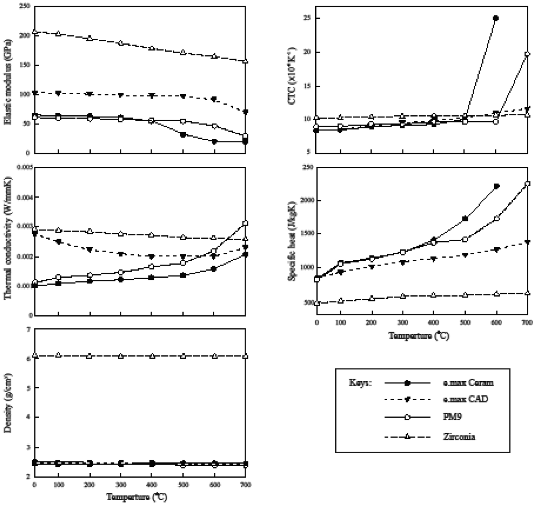
Materials properties as a function of temperature.
2.4. Viscoelastic Finite Element Analysis
Two 3D axial-symmetric crown models were created in the FEM software ABAQUS (Dassault Systèmes Simulia, Rhode Island, USA) (Figure 3). Both models were 8 mm height, had an outer diameter of 12 mm and a total thickness of 2.2 mm. The thickness ratios 2:1 and 1:1 were considered between veneer and core layers. Owing to the symmetric geometry, only 1/4th of the model was analyzed. To ensure axisymmetry, Y-Z face was restrained in the X-direction, X-Y face was restrained in the Z-direction and X-Z face in the Y-direction for both translation and rotation (Figure 3). Meshes consisted of 125,000 8-node brick elements. Density, CTC, specific heat, thermal conductivity, and elastic modulus as a function of the temperature were used to characterize each ceramic system (PVLD or PVZ). For each of the four design conditions, simulation was carried out in two steps: heat transfer analysis followed by viscoelastic stress analysis. For heat analysis entire model was held at an initial temperature of 754°C and then cooled to room temperature by subjecting the outer surfaces to heat transfer coefficients of 1.74e−4 W/mm2°C for fast cooling (~300°C/min) and 1.74e−5 W/mm2°C for slow cooling (30°C/min). The temperature profiles obtained (Figure 4) were then used as loads for the subsequent stress analysis. For stress analysis, user defined subroutines UEXPAN and UTRS, developed by Kim et al [32], were used to accurately capture viscoelastic behavior of the materials. The reference temperature from which cooling begins was considered to be 70°C above the softening temperature (Ts) of the porcelains. Cooling protocols simulated in both ceramic systems are described in Figure 4. The shear stress behavior in a viscoelastic material model when subjected to small shear strain considered in this study was described by Kim et al. [32] The viscoelastic parameters that were used are provided in Table 2. Same parameters were considered for both the material systems with varying reference temperatures. The viscoelastic materials show thermo-rheologically simple behavior in which the normalized shear relaxation function when plotted against log10t has same shape at each temperature. Hence, it can be shifted along the x-axis, thereby resulting in a master curve at that reference temperature [37]. Figure 5 shows the thermo-rheological behavior of PM9 using the coefficients described in Table 2. UTRS subroutine was used to capture this temperature dependency of viscoelastic parameters for both material systems.
Figure 3.
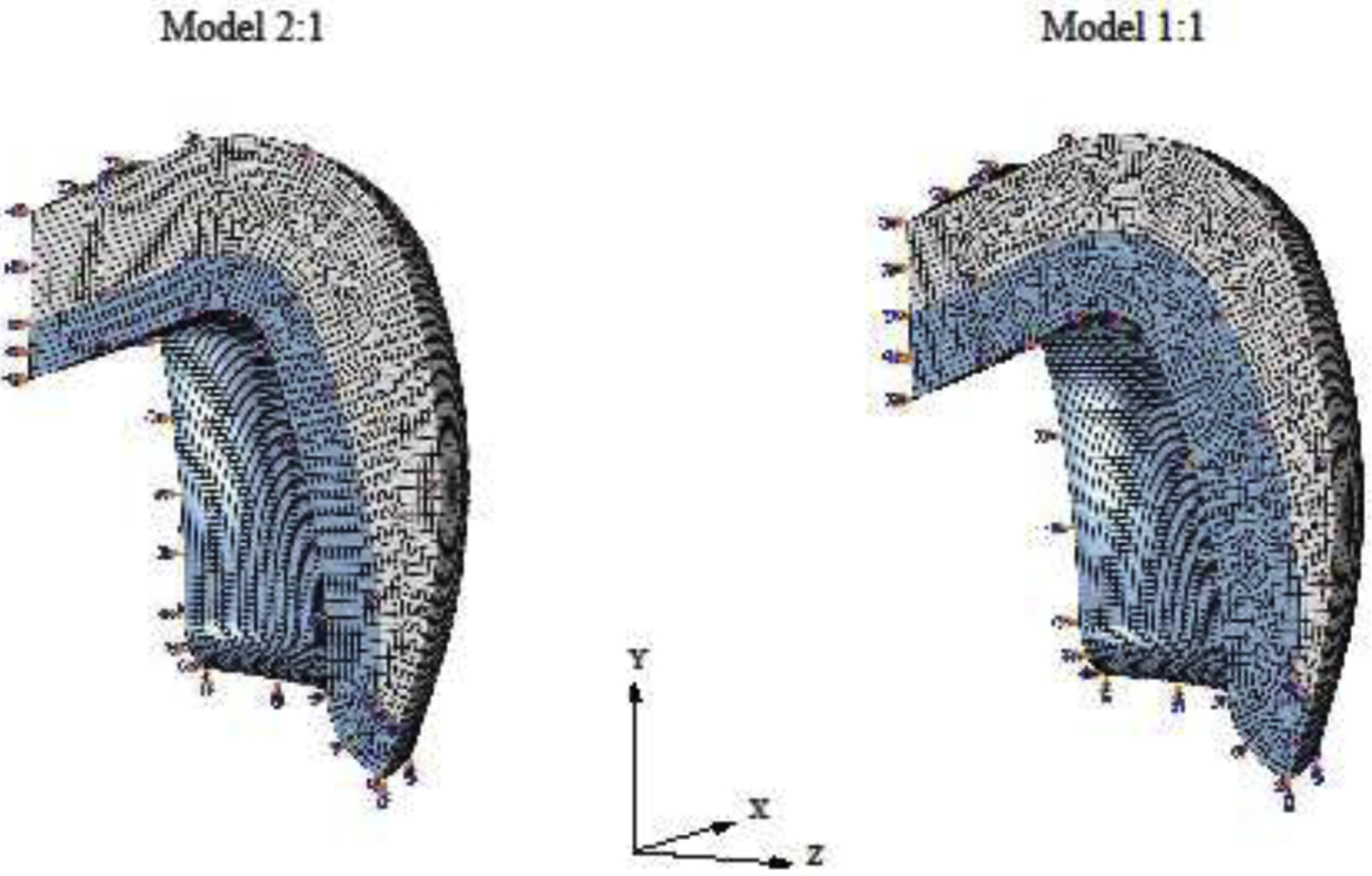
Models of the 1/4th crowns simulated in both thickness ratios. To ensure axisymmetry, Y-Z face was restrained in the x-direction, X-Y face was restrained in the z-direction, and X-Z face in the y-direction for both translation and rotation.
Figure 4.
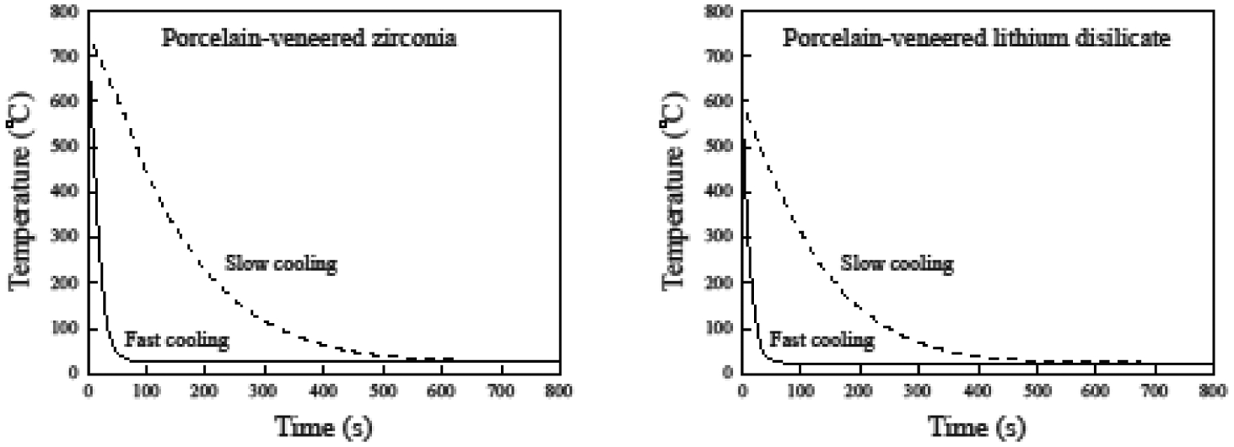
Cooling protocols simulated with VFEM.
Table 2.
Table 2 provides viscoelastic coefficients for the porcelain veneers at the reference temperature of 700°C [52], which are used to define the shear relaxation modulus in ABAQUS, using four-term Prony series.
| g 1 | g 2 | g 3 | g 4 | τ 1 | τ 2 | τ 3 | τ 4 |
|---|---|---|---|---|---|---|---|
| 0.9960 | 0.0030 | 0.0006 | 0.0004 | 0.0132 | 0.1000 | 0.0050 | 0.0030 |
Figure 5.
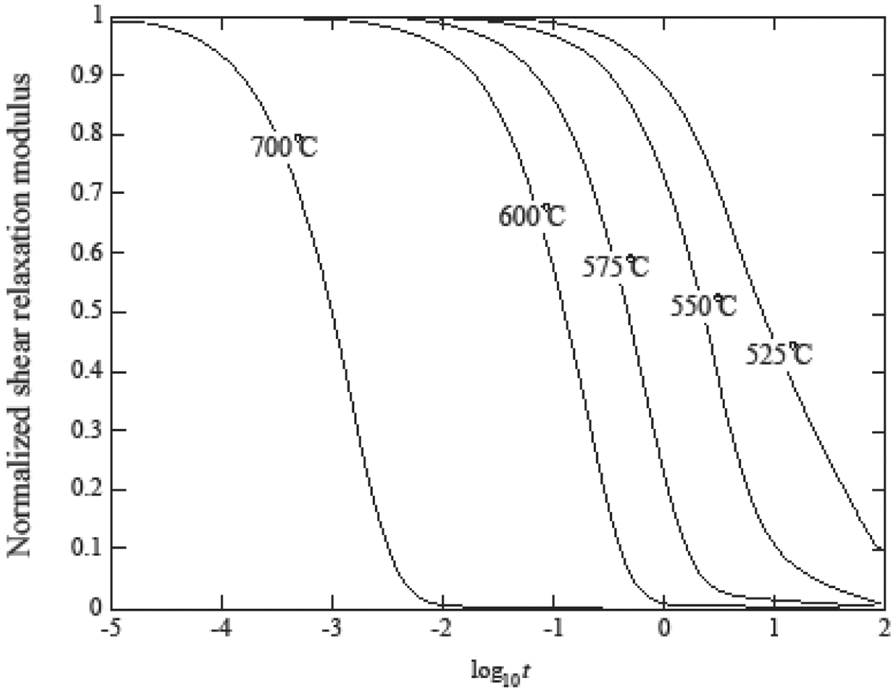
Normalized shear relaxation function at various temperatures [37].
The residual stresses and their distribution in each design condition were analyzed and 6 key points of the models were selected to analyze the stress history during the cooling phase (transient stresses).
3. Results
3.1. Experimental Validation of the VFEM Model
Figure 6 compares the stresses predicted by the VFEM with the experimental results obtained from flat samples. The agreement between the VFEM results and experimental measurements was considered good with maximum difference of 5 MPa when close to the interface. Therefore, this modelling showed the effectiveness of our VFEM codes in accurately capturing the viscoelastic behavior of materials.
Figure 6.
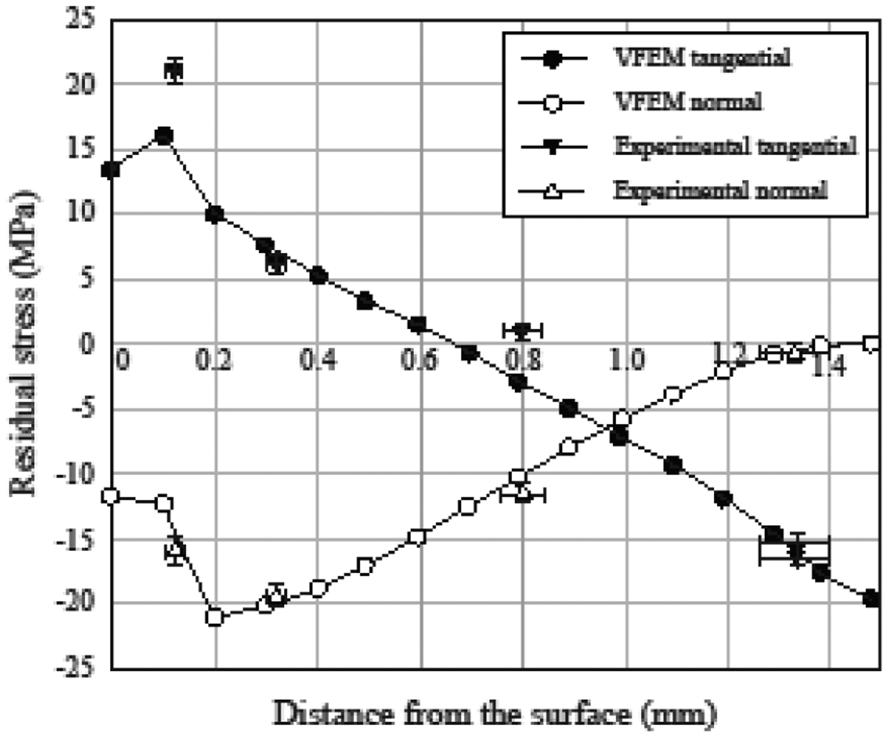
Residual stresses in PVLD bars. Stress profiles through porcelain thickness showing VFEM predictions (solid lines) agreeing with the experimental data (triangles).
3.2. VFEM Stress Analysis of Bilayer Crowns
Figure 7 shows the residual stress distribution and the maximum tensile stresses values found in both framework and porcelain layers in each simulation. Slow cooling led to lower residual stresses in the porcelain of both bilayer systems. However, the difference between the stresses developed in the porcelain with slow and fast cooling was as low as 3 MPa in PVZ. On the other hand, the effect of cooling rate in all simulations is more evident in transient stresses (Figure 8). Fast cooling led to an abrupt change in stresses in both materials and for the two thickness ratios simulated, as clearly illustrated in Figure 9. Taking the results from Figures 8 and 9 together, it becomes apparent that the spontaneous fluctuation in transient stress occurred within the first 30 s in fast cooling and 300 s in slow cooling. This corresponds to the period where the temperature had the steepest fall. Beyond that, the transient stress settled down and reached a plateau while the temperature gradually approached room temperature. More importantly, the initial spike of transient stress in PVLD was 2 times higher for fast cooling than slow cooling. Such a difference became more pronounced in PVZ, where the initial transient stress in fast cooling was over 5 times greater than that in slow cooling.
Figure 7.
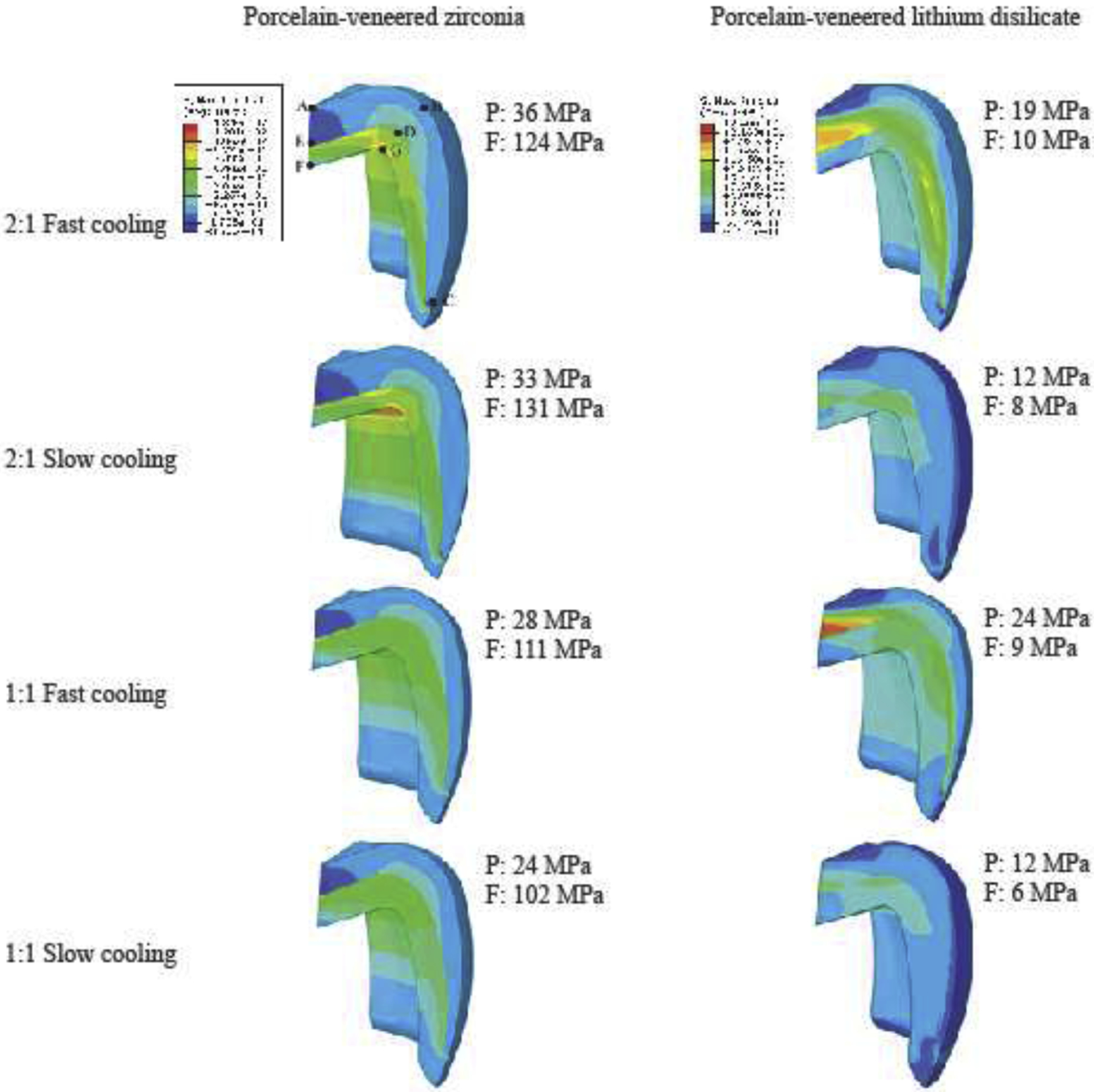
Residual stresses distribution and the maximum tensile stresses observed in porcelain (P) and framework (F) layers of each condition simulated. A, B, C, D, E, G are the nodes selected for the transient stresses analysis (Figure 8).
Figure 8.
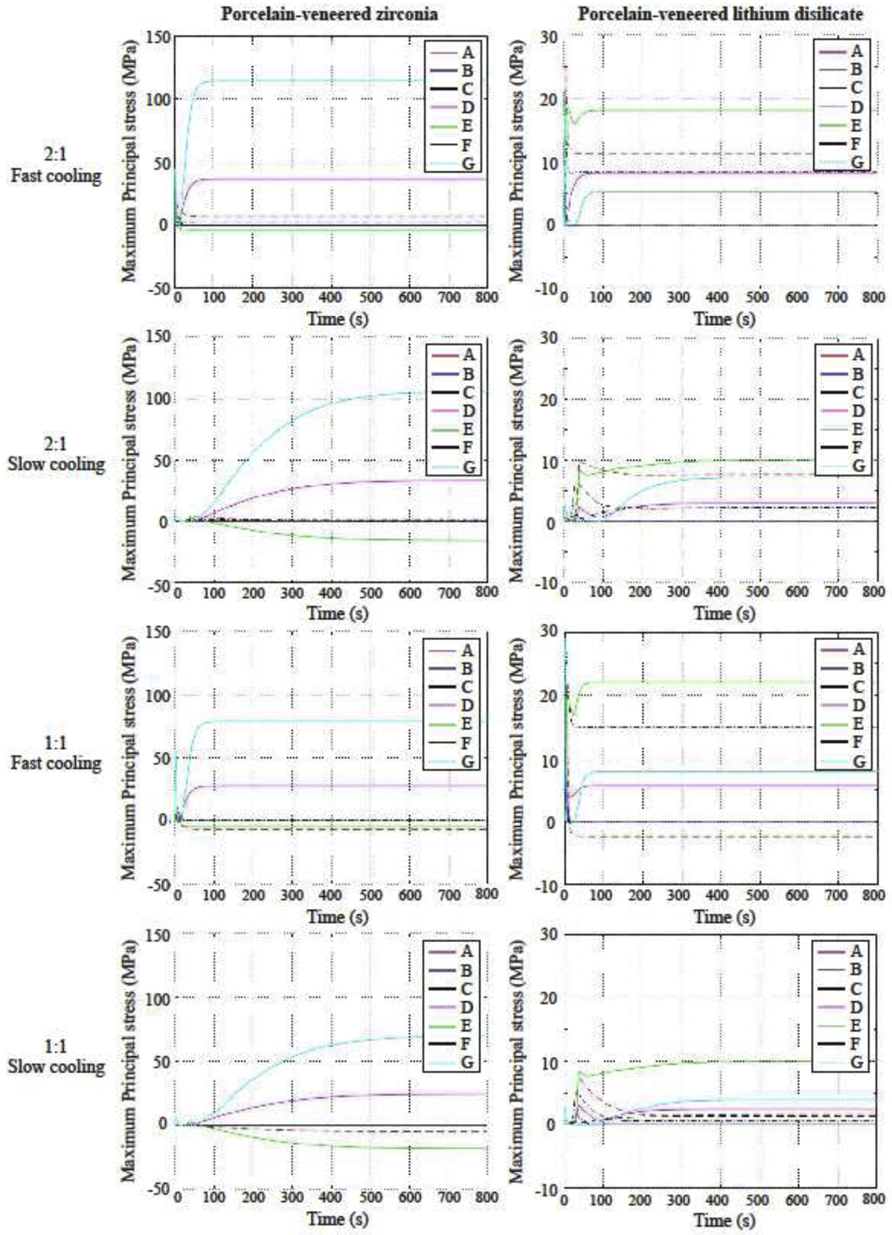
Stresses development in the six nodes of each condition simulated. Note that the stress plateau of each node was reached between 400 s and 600 s during slow cooling and before 100 s of simulation during fast cooling.
Figure 9.
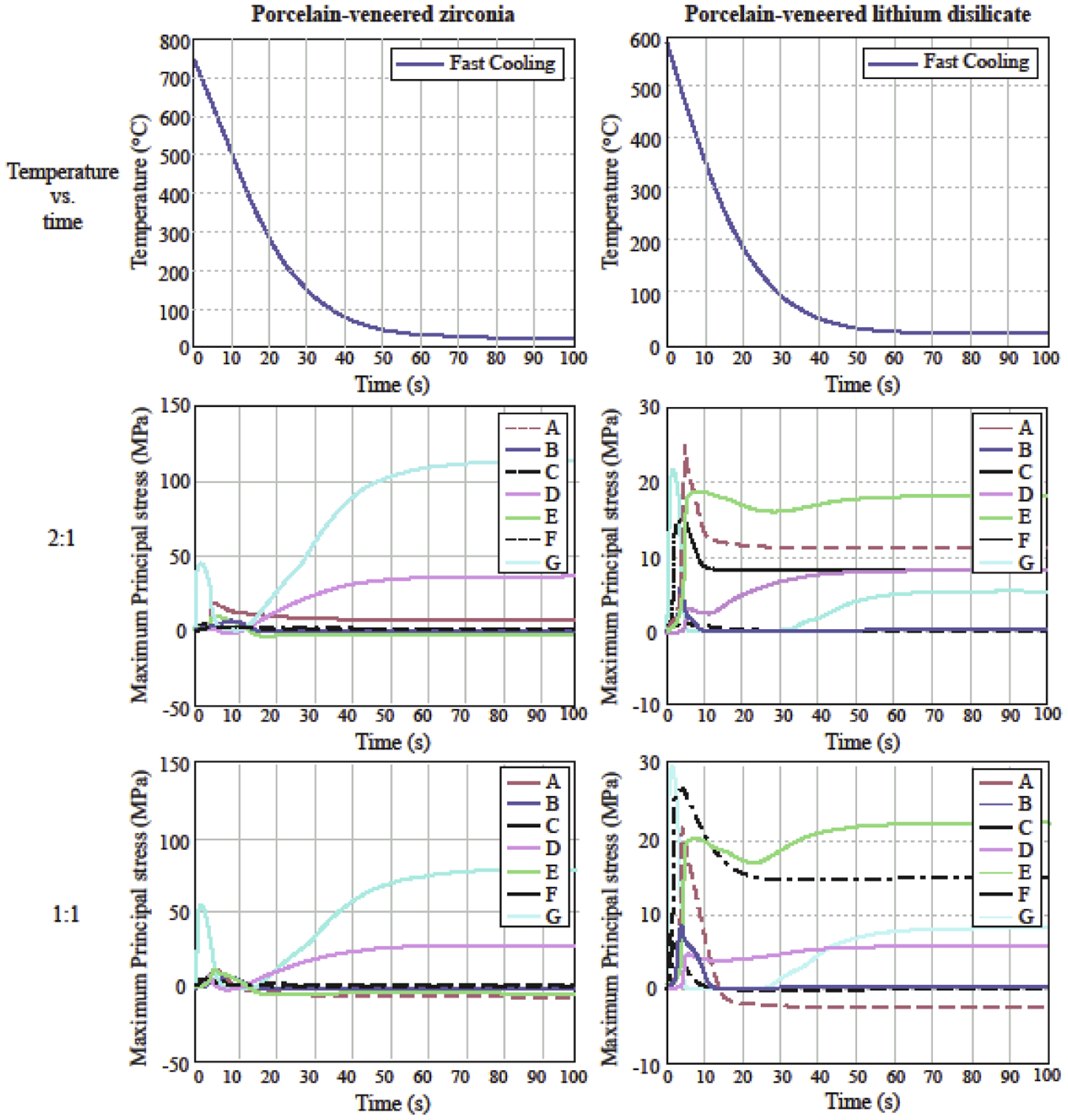
Magnified temperature profile and transient stresses in PVZ and PVLD crowns of 2:1 and 1:1 thickness ratios upon fast cooling.
The thickness ratio 1:1 led to lower residual stresses in both layers of PVZ. For PVLD subjected to fast cooling, the stresses in framework were almost the same; however, the thinner porcelain layer slightly increased the stresses (5 MPa higher). When slow cooling was applied, the stresses in 2:1 and 1:1 ratio models were very similar in both layers of PVLD.
PVLD showed lower residual stress values in all simulations, compared to PVZ, especially in the framework. The lowest stress (best condition) found in the porcelain for PVZ was 24 MPa (1:1 ratio, slow cooling); while the highest stress (worst condition) found in PVLD was also 24 MPa (1:1 ratio, fast cooling). In addition, the maximum tensile stresses in PVZ were located in the cusps close to the interface, while PVLD developed the highest stresses in the inner central fossa. To better correlate our VFEM results with clinical findings, the direction of the maximum principal stress in the veneer layer of both these material systems is shown in Figure 10. For PVZ systems, the maximum principal stress at the cusp acts normal to the cusp face and is directed towards the core. However, for PVLD systems, the maximum principal stresses act tangent to node E (see Figure 7).
Figure 10.
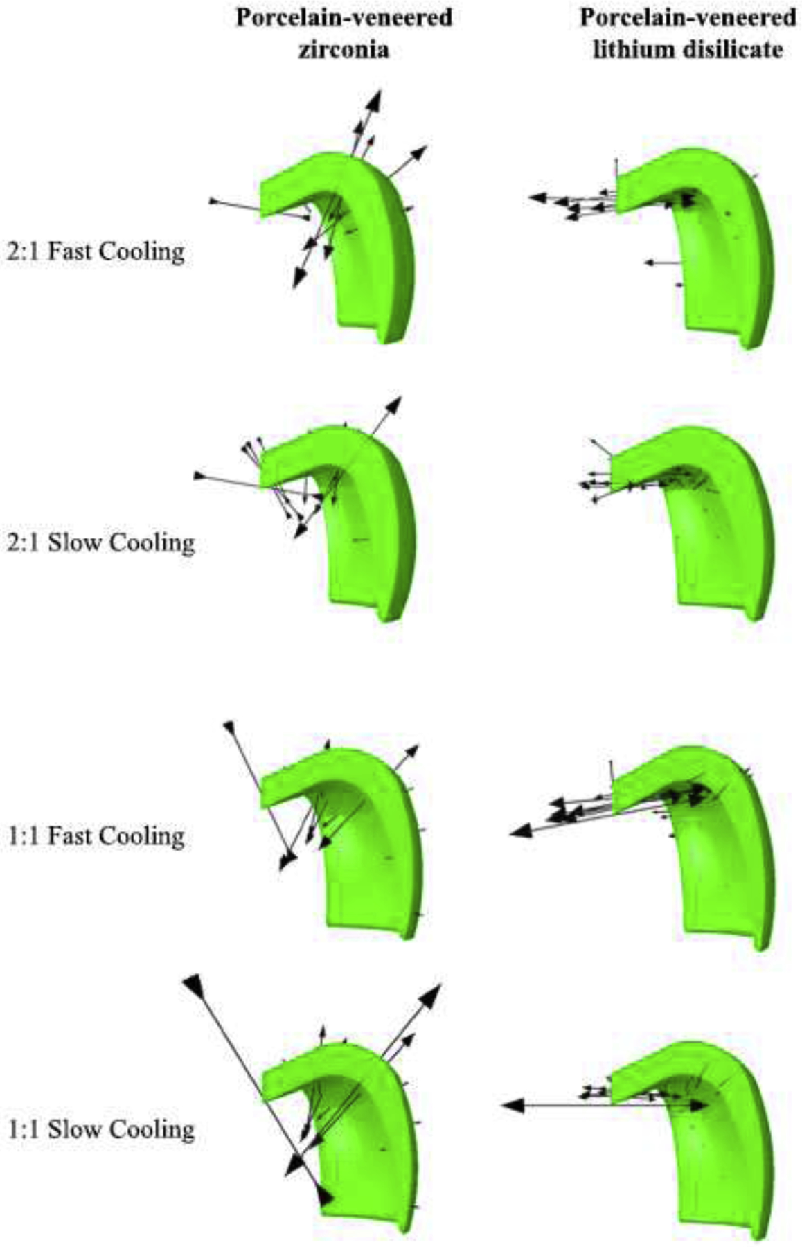
Direction of maximum principal stress in the veneer layer of PVZ and PVLD. For PVZ, the maximum principal stress at the cusp acts normal to the cusp face and is directed towards the core. For PVLD, it acts tangent to node E (see Figure 7).
4. Discussion
The studied metal-free bilayer systems were differently affected by thickness ratios and cooling rates, as well as the stress distribution throughout the crowns were different. Models with a lithium disilicate framework developed lower transient and residual stresses than the ones with zirconia framework. PVZ crowns showed up to 2.8 times higher residual stresses than PVLD in the porcelain layer and 16.4 times higher in the framework when comparing the same conditions of thickness and cooling. Thus, the first tested hypothesis should be accepted.
Previous researches have argued that the low thermal conductivity of zirconia may be an important factor to generate stresses in the porcelain layer. [29, 38, 39] However, the thermal conductivity of lithium disilicate is even lower than zirconia and the magnitude of stresses observed was much lower. Previous studies have proved that the greater the CTE mismatch between porcelain and zirconia, the greater the residual tensile stresses throughout the restoration. [32, 40] Given that, we believe rather than thermal conductivity, the CTE mismatch between the veneer and core is an important influencing factor in residual stresses. In this study, the CTE differences are somewhat similar in the two bilayer systems. Therefore, the residual stress will depend more on the elastic modulus difference and the glass transition temperature. In fact, the lower elastic modulus of the lithium disilicate (103 GPa) framework relative to the zirconia (206 GPa), and the lower glass transition temperature of the porcelain overlay for lithium disilicate played an important role in the stresses developed, leading to the differences we found. One should note that, since the stress is directly proportional to the modulus, a higher elastic modulus leads to higher thermal stress. In addition, as e.max Ceram has a lower Tg than PM9, it stays in the liquid phase for a longer time during cooling, which allows the eutectic veneer layer to accommodate any dimensional change of the framework, resulting in lower stresses, especially when slow cooling is applied.
Slow cooling was the best cooling condition for both systems, especially due to the transient stresses generated in key points of the crowns, suggesting that the second tested hypothesis could also be accepted. Slow cooling is well known to be the best option to improve stress behavior of porcelain-veneered zirconia compared to fast cooling. [41–45] Previous literature that used FEM to evaluate residual stresses in PVZ have reported lower values in slow cooling, [20, 22, 26] which have been associated with the improved mechanical behavior observed in in vitro tests. However, these papers have used linear finite element methods (LFEM), which was demonstrated to be less accurate to capture the stress profile than the viscoelastic finite element method. [32] In contrast, our findings obtained with VFEM showed that residual stresses are very similar comparing slow and fast cooling. The main difference was actually found in the transient stresses, which the stresses magnitude abruptly changed with fast cooling (Figure 8). As pointed out by Benetti et al (2014), [19] the magnitude of transient stresses generated by fast cooling is believed to create crack nucleation and fractures of the solid-state porcelain. Moreover, if there are some impurities or defects in the porcelain and the transient stress exceeds the threshold for fracture, it might lead to premature failure of the restoration.
PVZ showed to be more sensitive to thickness ratio than PVLD, which led the third tested hypothesis to be partially accepted. PVZ crowns showed a drop in residual stresses of ~20% in both layers when a 1:1 ratio was used. These results are in agreement with in vitro studies that found improved mechanical behavior of PVZ when a thicker copping was applied. [45, 46] On the other hand, residual stresses in PVLD crowns were very similar in 1:1 and 2:1 models, especially when slow cooling was applied. Thicker porcelain layer has been related to strong gradients in stresses. [19] As the specific heat of zirconia is almost half of the porcelains and lithium disilicate, it cools down easier. When the zirconia layer and the outer surface of porcelain are already at a lower temperature, the inner porcelain is still at a high temperature. When the inner porcelain finally solidifies, it creates tensile stresses due to glass contraction. In contrast, the specific heat of e.max CAD and e.max Ceram are very similar, which makes both layers cool down similarly, regardless of the thickness ratio.
Clinical studies show that minor chipping is a very frequent complication in PVZ crowns. [4, 5] Chipping is a type of failure related to contact damage. Besides, our residual stress analysis showed that the maximum tensile stresses of the porcelain are located in the cusp area. Occlusal contact damage is more likely to form near the cusp area. Once the crack forms, it readily enters the tensile stress zone, leading to veneer chipping. On the other hand, most studies show higher survival rates for PVLD crowns than PVZ in long-term follow-up [2, 5, 6] and, from the failed restorations, major chipping and bulk fracture are the most common reason. [7, 9] The maximum stress in PVLD is located in the central fossa, which together with the low magnitude of stress; it does not facilitate rapid crack propagation to the peripheral areas of the crowns. Therefore, any occlusal contact induced crack would have to propagate longer distance in order to cause a chip off fracture. Although it needs more effort for a crack to propagate longer distance, once it fractures it forms a major chipping.
Contrary to cracks originating from the contact damage at the occlusal surface, [47, 48] bulk fracture is related to flexural damage at the cementation surface. [49, 50] As zirconia is twice as strong as lithium disilicate, bulk fractures are not common in this system. Thus, bulk fracture are more willing to happen in PVLD crowns, originating from the cementation surface by radial cracks underneath the contact area. Interestingly, the veneer-core thickness ratio does not interfere with the flexural damage resistance of PVZ and PVLD, especially in the thickness ratio between 1:4 and 4:1. [51] However, thick porcelain layer leads to strong gradients in stresses, which makes cracks originating from contact damage easy to propagate. Therefore, the interaction between thickness ratio and residual stresses is more associated with susceptibility to chipping than bulk fracture.
Our findings showed that porcelain-veneered zirconia and porcelain-veneered lithium disilicate are differently affected by layer thicknesses and cooling rates, hence leading to different transient and residual stress magnitudes and distributions. This difference is supposed to have some effect on their clinical behaviors, since areas of high tensile stresses contribute to crack propagation. Even though in vivo studies are the best evidence for clinical behavior of restorations, isolating each of these factors (material, thickness, cooling rate) in a clinical study would be challenging and time-consuming. Therefore, correlating VFEM with clinical findings provides a practical option for understanding the implications of materials properties and restorations planning on its clinical performance. In addition, in vitro studies (e.g. load-bearing capacity, fatigue tests) are encouraged to confirm the association between stress distributions and failure modes, as well as planning studies with implant-retained crowns and multiple-unit fixed dental prosthesis.
5. Conclusions
Bilayer crowns with lithium disilicate framework develop lower transient and residual stresses than porcelain-veneered zirconia. Slow cooling is preferable for both PVZ and PVLD, mainly because of its effects on transient stresses. Using a thinner porcelain layer over zirconia when possible is preferable to reduce stresses throughout the restoration. However, thickness ratio does not play an important role in stresses developed in PVLD once a slow cooling protocol is applied. In addition to the above mentioned, crown geometric and processing parameters, a small mismatch in elastic modulus, coefficient of thermal expansion, specific heat between the veneer and core as well as the utilization of low Tg porcelains are key material properties for minimizing the deleterious transient and residual tensile stresses in porcelain-veneered all-ceramic restorations.
Highlights.
PVLD crowns exhibited lower transient and residual stresses than PVZ crowns.
Slow cooling significantly reduced transient stresses but not residual stresses.
PVZ crowns were more sensitive to layer thickness ratio than PVLD crowns.
Material properties responsible for the deleterious tensile stresses were identified.
Associations between stress distribution and clinical fractures were made by VFEM.
Acknowledgements
The authors are thankful to the Federal Agency for Support and Evaluation of Graduate Education (CAPES) (finance code 001). This study was supported by the U.S. National Institute of Dental and Craniofacial Research (Grant Nos. R01DE026279 and R01DE026772).
Footnotes
Publisher's Disclaimer: This is a PDF file of an unedited manuscript that has been accepted for publication. As a service to our customers we are providing this early version of the manuscript. The manuscript will undergo copyediting, typesetting, and review of the resulting proof before it is published in its final form. Please note that during the production process errors may be discovered which could affect the content, and all legal disclaimers that apply to the journal pertain.
References
- [1].Zhang Y, Kelly JR. Dental ceramics for restoration and metal veneering. Dent Clin North Am. 2017;61:797–819. [DOI] [PMC free article] [PubMed] [Google Scholar]
- [2].Dhima M, Paulusova V, Carr AB, Rieck KL, Lohse C, Salinas TJ. Practice-based clinical evaluation of ceramic single crowns after at least five years. J Prosthet Dent. 2014;111:124–30. [DOI] [PubMed] [Google Scholar]
- [3].Rinke S, Kramer K, Burgers R, Roediger M. A practice-based clinical evaluation of the survival and success of metal-ceramic and zirconia molar crowns: 5-year results. J Oral Rehabil. 2016;43:136–44. [DOI] [PubMed] [Google Scholar]
- [4].Gherlone E, Mandelli F, Cappare P, Pantaleo G, Traini T, Ferrini F. A 3 years retrospective study of survival for zirconia-based single crowns fabricated from intraoral digital impressions. J Dent. 2014;42:1151–5. [DOI] [PubMed] [Google Scholar]
- [5].Sailer I, Makarov NA, Thoma DS, Zwahlen M, Pjetursson BE. All-ceramic or metal-ceramic tooth-supported fixed dental prostheses (FDPs)? A systematic review of the survival and complication rates. Part I: Single crowns (SCs). Dent Mater. 2015;31:603–23. [DOI] [PubMed] [Google Scholar]
- [6].Malament KA, Natto ZS, Thompson V, Rekow D, Eckert S, Weber HP. Ten-year survival of pressed, acid-etched e.max lithium disilicate monolithic and bilayered complete-coverage restorations: performance and outcomes as a function of tooth position and age. J Prosthet Dent. 2019;121:782–90. [DOI] [PubMed] [Google Scholar]
- [7].Simeone P, Gracis S. Eleven-year retrospective survival study of 275 veneered lithium disilicate single crowns. Int J Periodontics Restorative Dent. 2015;35:685–94. [DOI] [PubMed] [Google Scholar]
- [8].Valenti M, Valenti A. Retrospective survival analysis of 261 lithium disilicate crowns in a private general practice. Quintessence Int. 2009;40:573–9. [PubMed] [Google Scholar]
- [9].Yang Y, Yu J, Gao J, Guo J, Li L, Zhao Y, et al. Clinical outcomes of different types of tooth-supported bilayer lithium disilicate all-ceramic restorations after functioning up to 5 years: A retrospective study. J Dent. 2016;51:56–61. [DOI] [PubMed] [Google Scholar]
- [10].Zhang Y, Sailer I, Lawn BR. Fatigue of dental ceramics. J Dent. 2013;41:1135–47. [DOI] [PMC free article] [PubMed] [Google Scholar]
- [11].Scherrer SS, Lohbauer U, Della Bona A, Vichi A, Tholey MJ, Kelly JR, et al. ADM guidance-Ceramics: guidance to the use of fractography in failure analysis of brittle materials. Dent Mater. 2017;33:599–620. [DOI] [PubMed] [Google Scholar]
- [12].Rekow ED, Silva NR, Coelho PG, Zhang Y, Guess P, Thompson VP. Performance of dental ceramics: challenges for improvements. J Dent Res. 2011;90:937–52. [DOI] [PMC free article] [PubMed] [Google Scholar]
- [13].Kokubo Y, Tsumita M, Kano T, Fukushima S. The influence of zirconia coping designs on the fracture load of all-ceramic molar crowns. Dent Mater J. 2011;30:281–5. [DOI] [PubMed] [Google Scholar]
- [14].Shirakura A, Lee H, Geminiani A, Ercoli C, Feng C. The influence of veneering porcelain thickness of all-ceramic and metal ceramic crowns on failure resistance after cyclic loading. J Prosthet Dent. 2009;101:119–27. [DOI] [PubMed] [Google Scholar]
- [15].Rekow ED, Zhang G, Thompson V, Kim JW, Coehlo P, Zhang Y. Effects of geometry on fracture initiation and propagation in all-ceramic crowns. J Biomed Mater Res B Appl Biomater. 2009;88:436–46. [DOI] [PubMed] [Google Scholar]
- [16].Cheung KC, Darvell BW. Sintering of dental porcelain: effect of time and temperature on appearance and porosity. Dent Mater. 2002;18:163–73. [DOI] [PubMed] [Google Scholar]
- [17].Belli R, Frankenberger R, Appelt A, Schmitt J, Baratieri LN, Greil P, et al. Thermal-induced residual stresses affect the lifetime of zirconia-veneer crowns. Dent Mater. 2013;29:181–90. [DOI] [PubMed] [Google Scholar]
- [18].Hermann I, Bhowmick S, Zhang Y, Lawn BR. Competing fracture modes in brittle materials subject to concentrated cyclic loading in liquid environments: trilayer structures. J Mater Res. 2006;21:512–21. [Google Scholar]
- [19].Benetti P, Kelly JR, Sanchez M, Della Bona A. Influence of thermal gradients on stress state of veneered restorations. Dent Mater. 2014;30:554–63. [DOI] [PubMed] [Google Scholar]
- [20].Meira JBC, Reis BR, Tanaka CB, Ballester RY, Cesar PF, Versluis A, et al. Residual stresses in Y-TZP crowns due to changes in the thermal contraction coefficient of veneers. Dent Mater. 2013;29:594–601. [DOI] [PubMed] [Google Scholar]
- [21].Taskonak B, Borges GA, Mecholsky JJ, Anusavice KJ, Moore BK, Yan J. The effects of viscoelastic parameters on residual stress development in a zirconia/glass bilayer dental ceramic. Dent Mater. 2008;24:1149–55. [DOI] [PubMed] [Google Scholar]
- [22].Tanaka CB, Ballester RY, De Souza GM, Zhang Y, Meira JBC. Influence of residual thermal stresses on the edge chipping resistance of PFM and veneered zirconia structures: Experimental and FEA study. Dent Mater. 2019;35:344–55. [DOI] [PMC free article] [PubMed] [Google Scholar]
- [23].Dhital S, Rodrigues C, Zhang Y, Kim J. Viscoelastic finite element evaluation of transient and residual stresses in dental crowns: design parametric study. J Mech Behav Biomed Mater. 2019;103:103545. [DOI] [PMC free article] [PubMed] [Google Scholar]
- [24].Baldassarri M, Stappert CF, Wolff MS, Thompson VP, Zhang Y. Residual stresses in porcelain-veneered zirconia prostheses. Dent Mater. 2012;28:873–9. [DOI] [PMC free article] [PubMed] [Google Scholar]
- [25].Choi JE, Waddell JN, Swain MV. Pressed ceramics onto zirconia. Part 2: indentation fracture and influence of cooling rate on residual stresses. Dent Mater. 2011;27:1111–8. [DOI] [PubMed] [Google Scholar]
- [26].Tanaka CB, Harisha H, Baldassarri M, Wolff MS, Tong H, Meira JB, et al. Experimental and finite element study of residual thermal stresses in veneered Y-TZP structures. Ceram Int. 2016;42:9214–21. [DOI] [PMC free article] [PubMed] [Google Scholar]
- [27].Wendler M, Belli R, Petschelt A, Lohbauer U. Characterization of residual stresses in zirconia veneered bilayers assessed via sharp and blunt indentation. Dent Mater. 2015;31:948–57. [DOI] [PubMed] [Google Scholar]
- [28].Belli R, Monteiro S Jr., Baratieri LN, Katte H, Petschelt A, Lohbauer U. A photoelastic assessment of residual stresses in zirconia-veneer crowns. J Dent Res. 2012;91:316–20. [DOI] [PubMed] [Google Scholar]
- [29].Tholey MJ, Swain MV, Thiel N. Thermal gradients and residual stresses in veneered Y-TZP frameworks. Dent Mater. 2011;27:1102–10. [DOI] [PubMed] [Google Scholar]
- [30].Wendler M, Belli R, Petschelt A, Lohbauer U. Spatial distribution of residual stresses in glass-ZrO2 sphero-cylindrical bilayers. J Mech Behav Biomed Mater. 2016;60:535–46. [DOI] [PubMed] [Google Scholar]
- [31].Mainjot AK, Schajer GS, Vanheusden AJ, Sadoun MJ. Influence of cooling rate on residual stress profile in veneering ceramic: measurement by hole-drilling. Dent Mater. 2011;27:906–14. [DOI] [PubMed] [Google Scholar]
- [32].Kim J, Dhital S, Zhivago P, Kaizer MR, Zhang Y. Viscoelastic finite element analysis of residual stresses in porcelain-veneered zirconia dental crowns. J Mech Behav of Biomed Mater. 2018;82:202–9. [DOI] [PMC free article] [PubMed] [Google Scholar]
- [33].Dhital S, Rodrigues C, Zhang Y, Kim J. Metal-ceramic and porcelain-veneered lithium disilicate crowns: a stress profile comparison using a viscoelastic finite element model. Comput Methods Biomech Biomed Engin. 2021:1–12. [DOI] [PMC free article] [PubMed] [Google Scholar]
- [34].Zeng KY, Rowcliffe D. Experimental-measurement of residual-stress field around a sharp indentation in glass. J Am Ceram Soc. 1994;77:524–30. [Google Scholar]
- [35].Quinn JB, Sundar V, Lloyd IK. Influence of microstructure and chemistry on the fracture toughness of dental ceramics. Dent Mater. 2003;19:603–11. [DOI] [PubMed] [Google Scholar]
- [36].Tong H, Tanaka CB, Kaizer MR, Zhang Y. Characterization of three commercial Y-TZP ceramics produced for their high-translucency, high-strength and high-surface area. Ceram Int. 2016;42:1077–85. [DOI] [PMC free article] [PubMed] [Google Scholar]
- [37].DeHoff PH, Anusavice KJ, Götzen N. Viscoelastic finite element analysis of an all-ceramic fixed partial denture. J Biomech. 2006;39:40–8. [DOI] [PubMed] [Google Scholar]
- [38].Mainjot AK, Schajer GS, Vanheusden AJ, Sadoun MJ. Residual stress measurement in veneering ceramic by hole-drilling. Dent Mater. 2011;27:439–44. [DOI] [PubMed] [Google Scholar]
- [39].Kim JW, Kim JH, Janal MN, Zhang Y. Damage maps of veneered zirconia under simulated mastication. J Dent Res. 2008;87:1127–32. [DOI] [PMC free article] [PubMed] [Google Scholar]
- [40].Jikihara AN, Tanaka CB, Ballester RY, Swain MV, Versluis A, Meira JBC. Why a zero CTE mismatch may be better for veneered Y-TZP structures. J Mech Behav Biomed Mater. 2019;96:261–8. [DOI] [PubMed] [Google Scholar]
- [41].Paula VG, Lorenzoni FC, Bonfante EA, Silva NR, Thompson VP, Bonfante G. Slow cooling protocol improves fatigue life of zirconia crowns. Dent Mater. 2015;31:77–87. [DOI] [PubMed] [Google Scholar]
- [42].Preis V, Letsch C, Handel G, Behr M, Schneider-Feyrer S, Rosentritt M. Influence of substructure design, veneer application technique, and firing regime on the in vitro performance of molar zirconia crowns. Dent Mater. 2013;29:e113–21. [DOI] [PubMed] [Google Scholar]
- [43].Rodrigues CDS, Aurelio IL, Kaizer MDR, Zhang Y, May LG. Do thermal treatments affect the mechanical behavior of porcelain-veneered zirconia? A systematic review and meta-analysis. Dent Mater. 2019;35:807–17. [DOI] [PMC free article] [PubMed] [Google Scholar]
- [44].Rues S, Kroger E, Muller D, Schmitter M. Effect of firing protocols on cohesive failure of all-ceramic crowns. J Dent. 2010;38:987–94. [DOI] [PubMed] [Google Scholar]
- [45].Tang YL, Kim JH, Shim JS, Kim S. The effect of different cooling rates and coping thicknesses on the failure load of zirconia-ceramic crowns after fatigue loading. J Adv Prosthodont. 2017;9:152–8. [DOI] [PMC free article] [PubMed] [Google Scholar]
- [46].Alhasanyah A, Vaidyanathan TK, Flinton RJ. Effect of core thickness differences on post-fatigue indentation fracture resistance of veneered zirconia crowns. J Prosthodont. 2013;22:383–90. [DOI] [PubMed] [Google Scholar]
- [47].Ren L, Zhang Y. Sliding contact fracture of dental ceramics: principles and validation. Acta Biomater. 2014;10:3243–53. [DOI] [PMC free article] [PubMed] [Google Scholar]
- [48].Zhang Y, Bhowmick S, Lawn BR. Competing fracture modes in brittle materials subject to concentrated cyclic loading in liquid environments: monoliths. J Mater Res. 2005;20:2021–9. [Google Scholar]
- [49].Bhowmick S, Zhang Y, Lawn BR. Competing fracture modes in brittle materials subject to concentrated cyclic loading in liquid environments: bilayer structures. J Mater Res. 2005;20:2792–800. [Google Scholar]
- [50].Zhang Y, Kim JW, Bhowmick S, Thompson VP, Rekow ED. Competition of fracture mechanisms in monolithic dental ceramics: flat model systems. J Biomed Mater Res B Appl Biomater. 2009;88:402–11. [DOI] [PMC free article] [PubMed] [Google Scholar]
- [51].Deng Y, Miranda P, Pajares A, Guiberteau F, Lawn BR. Fracture of ceramic/ceramic/polymer trilayers for biomechanical applications. J Biomed Mater Res A. 2003;67:828–33. [DOI] [PubMed] [Google Scholar]
- [52].DeHoff PH, Barrett AA, Lee RB, Anusavice KJ. Thermal compatibility of dental ceramic systems using cylindrical and spherical geometries. Dent Mater. 2008;24:744–52. [DOI] [PMC free article] [PubMed] [Google Scholar]


