Abstract
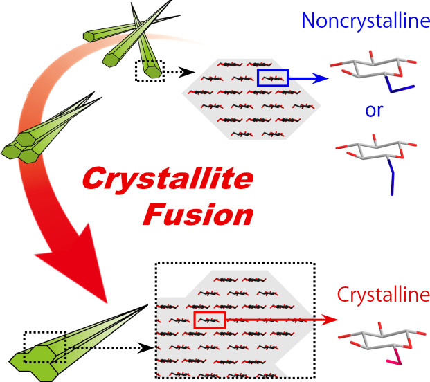
Crystallites form a grain boundary or the inter‐crystallite interface. A grain boundary is a structural defect that hinders the efficient directional transfer of mechanical stress or thermal phonons in crystal aggregates. We observed that grain boundaries within an aggregate of crystalline cellulose nanofibers (CNFs) were crystallized by enhancing their inter‐crystallite interactions; multiple crystallites were coupled into single fusion crystals, without passing through a melting or dissolving state. Accordingly, the lowered crystallinity of CNFs, which has been considered irreversible, was recovered, and the thermal energy transfer in the aggregate was significantly improved. Other nanofibrous crystallites of chitin also showed a similar fusion phenomenon by enhancing the inter‐crystallite interactions. Such crystallite fusion may naturally occur in biological structures with network skeletons of aggregated fibrillar crystallites having mechanical or thermal functions.
Keywords: cellulose nanofibers, chitin, crystallinity, fusion, grain boundaries
Grain boundaries within an aggregate of crystalline cellulose nanofibers (CNFs) are crystallized by enhancing their inter‐crystallite interactions; multiple crystallites are coupled into single fusion crystals without passing through a melting or dissolving state. Accordingly, thermal energy transfer within the CNF aggregate is significantly improved.
Introduction
Mechanical and thermal energy transfers in crystal aggregates are governed by a grain boundary or the interface where multiple crystallites meet. [1] Proper crystallite interactions at the grain boundary can allow mechanical stress or thermal phonons to directionally transfer in the aggregate; however, a grain boundary is often a structural defect that deforms under stress or scatters phonons.[ 2 , 3 ] This feature becomes pronounced when the crystallites have nanoscale dimensions and form a large area of the grain boundary. In the field of nanotechnology, it is currently a challenge to exploit the potential of such nanoscale crystallites, including biopolymer fibrils and clay platelets, in bulk aggregates or composites by tailoring the interactions between crystallites or with other components.[ 4 , 5 , 6 ]
Ideal energy transfer in crystal aggregates must be realized by crystallization of the grain boundary. If multiple crystallites can be coupled into single fusion crystals by forming a bulk aggregate from their dispersions, scalable polycrystalline materials with more efficient mechanical and thermal energy transfers will be produced. However, crystallites often have disordered structures or defects at their surfaces,[ 4 , 7 ] hindering efficient energy transfer.
Herein, we report that grain boundaries within an aggregate of a‐few‐nanometers‐wide crystalline cellulose nanofibers (CNFs) were crystallized by enhancing the inter‐CNF interactions. CNFs are sustainable materials with excellent mechanical and thermal properties, which are produced as a water dispersion using wood pulps as the raw material. [8] Their elemental unit is a crystallite consisting of uniaxially oriented molecular chains, known as a cellulose microfibril.[ 9 , 10 ] In the dispersion, the surface molecules of CNFs have a thermodynamically stable, non‐crystalline conformation and are uniaxially oriented, similar to the inner crystalline molecules.[ 10 , 11 , 12 ]
We previously showed that the crystallinity of CNFs significantly decreased when aggregated microfibrils in a pulp dispersed as CNFs or separated into individual crystallites.[ 11 , 13 ] This phenomenon was interpreted to result from the exposure of the grain boundary that was partially crystallized in the microfibril aggregates. This study was aimed at recovering the decreased crystallinity of the CNFs by assembly. We also verified if the crystallization of the grain boundary led to greater efficiency in the thermal energy transfer of bulk crystal aggregates.
Results and Discussion
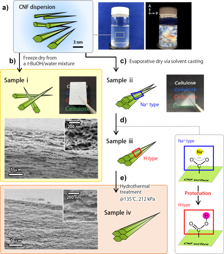
Scheme 1 shows the procedure for enhancing the inter‐CNF interactions in a bulk aggregate. The CNF dispersion was prepared by wet disintegration of a TEMPO‐oxidized wood pulp. [14] In the TEMPO‐oxidation reaction, the C6 hydroxy groups exposed on the microfibril surfaces are regioselectively oxidized, such that the resulting CNFs have width of 2–3 nm, are monodisperse and possess a high surface density of carboxy groups (up to ca. 1.7 groups per square nanometer). The carboxy groups are Na+ type at the initial step. By the dissociation of the carboxy groups, the CNFs are stably dispersed in water and spontaneously form a nematic liquid‐crystalline phase where the CNFs are uniaxially oriented in places (Scheme 1 a). [15] In this study, the nematic‐ordered CNF dispersion was assembled into dry sheets by two processes. One process was freeze drying from a 30 % tert‐butyl alcohol‐containing diluted dispersion, followed by pressing of the dried aerogel‐like product (sample i). [16] The other process was evaporative drying via solvent casting of the CNF dispersion at 40 °C under a high relative humidity of 80 %, resulting in the formation of transparent and flat dry sheets (sample ii). [17] Sample ii was further processed with a dilute acid solution to convert the carboxy groups from sodium salt into protonated acid form, H type (sample iii, see Figure S1a for the evidence of protonation), [18] followed by a hydrothermal treatment using a common autoclave at 135 °C and 212 kPa (sample iv). The hydrothermal treatment was adopted to enable the CNFs to rearrange and stabilize their interaction. Note that the CNFs remained solid, without melting or dissolving, under the conditions adopted in this study.
Scheme 1.
Procedure for enhancing the inter‐CNF interactions. a) The CNF dispersion forming a nematic liquid‐crystalline phase, including its appearance and birefringence image. b) Conversion to sample i. The assembled state of the CNFs in sample i, appearance, and cross‐sectional SEM images. c) Conversion to sample ii. d) Conversion to sample iii. e) Conversion to sample iv, including cross‐sectional SEM images.
The assembled states of the CNFs in each sheet are illustrated in Scheme 1 b–e: roughly oriented in sample i, and highly oriented in samples ii–iv. Meanwhile, the CNFs of samples i–iv were on average packed parallel to the sheet surface (see Figures S2 for X‐ray diffraction (XRD) diagrams). [17] The CNFs in samples iii and iv were also hydrogen‐bonded with one another via the surface carboxy groups, as analyzed by Fourier‐transform infrared (FTIR) spectroscopy (Figure S1a), and those in sample iv were more strongly hydrogen‐bonded (Figure S1b,c). Accordingly, the porosity of the samples decreased in the order of sample i>ii > iii>iv, at 16 %, 10 %, 9 %, and 4 %, respectively. The specific surface area (SSA) of sample i was ca. 6.3 m2 g−1, as measured by nitrogen adsorption analysis (Figure S3), whereas those of samples ii, iii, and iv were all below the limit of detection (ca. 2 m2 g−1). Therefore, the CNFs in each sample were considered to interact more closely or strongly in the order of sample i<ii<iii<iv.
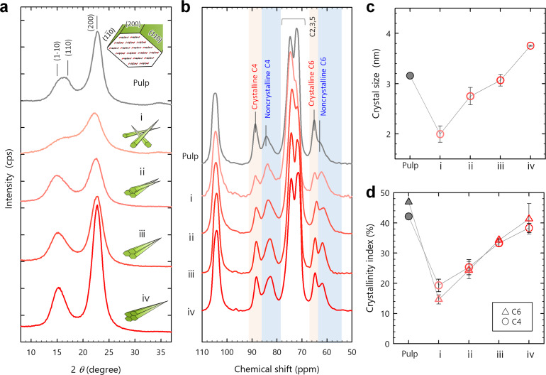
Figure 1 a shows powder XRD profiles of the oxidized starting pulp and CNF samples i–iv (see Figures S4 and S5a for the reproducibility). The XRD profiles of the pulp and sample i notably differed; all the peaks broadened and their intensities decreased. From sample i to ii, the peak widths narrowed. From sample ii to iv, the peaks further sharpened and intensified, and the (2 0 0) peak shifted slightly to the high‐angle side. Finally, sample iv exhibited a distinct XRD profile rather than the starting pulp.
Figure 1.
Recovery of crystallinity. a) XRD profiles and b) CP/MAS 13C NMR spectra of a series of samples ranging from the starting pulp to CNF samples i–iv. c) Crystal size of the (2 0 0) plane calculated from the XRD profiles, and d) crystallinity indices of the C4 and C6 carbon atoms calculated from the NMR spectra. Each plot shows the mean values with standard deviations estimated using three sets of samples i–iv.
The nuclear magnetic resonance (NMR) spectra for the samples are shown in Figure 1 b. In the C4 and C6 regions of the NMR spectra, the crystalline signals centered at 88 ppm (C4) and 65 ppm (C6) remarkably decreased at the first step of the pulp‐sample i conversion and increased in the order of samples ii, iii, and iv. Meanwhile, the non‐crystalline signals at 84 ppm (C4) and 62 ppm (C6) increased at the first step and then decreased in the order of samples ii, iii, and iv (see Figure S5b for the reproducibility).
As measures of the crystallinity, the Scherrer's crystal sizes of the (2 0 0) plane and crystallinity indices were calculated from the XRD profiles and NMR spectra, respectively (Figure 1 c,d). [11] The crystallinity indices were expressed in two different forms as area ratios of the crystalline and non‐crystalline signals in the C4 and C6 regions. Note that the crystalline C6 signal arises from the C6 carbon atoms turning the C6‐O6 bond to the “trans‐gauche (tg)” configuration against the C5‐O5/C4‐C5 bonds in anhydroglucose units. [10] Moreover, the crystalline C4 conformation is fixed with the intra/inter‐molecular hydrogen bonds via the tg‐configurational C6 hydroxy groups. The crystallinity indices thus reflect the degree of intra‐/inter‐molecular hydrogen bonding.
The (2 0 0) crystal size decreased from 3.5 nm to 2.0 nm by the pulp‐sample i conversion and increased up to 3.8 nm in the order of samples ii, iii, and iv (Figures 1 c and S5c). This increase in the crystal size explained the slight shift of the (2 0 0) peak position to the high‐angle side, according to a previous report. [19] Also, the two crystallinity indices of the C4 and C6 carbon atoms decreased by 25–30 % on the conversion to sample i, and then increased by 20–25 % for samples ii, iii, and iv (Figures 1 d and S5d). For both the crystal size and crystallinity index, the initial decrease was interpreted to result from the increase in SSA by disintegration of the pulp into the CNF dispersion (see Introduction). [11] The successive increase was thus attributed to assembly of the CNFs in dry sheets; the inter‐CNF interaction should be dominant in the recovery of crystallinity.
Interestingly, the final values for sample iv surpassed or approached the crystal size and crystallinity indices of the starting pulp; the crystallinity of the CNFs was reversible (see Figure S6 for the repeatability data). The recovery of crystallinity was also demonstrated for other type of CNFs produced from chemically unmodified, raw pulps solely by wet disintegration (Figure S7). Furthermore, other fibrillar crystallites of α‐chitin showed the recovery of crystallinity through the same process as the dispersion and assembly of CNFs in this study (Figure S8).
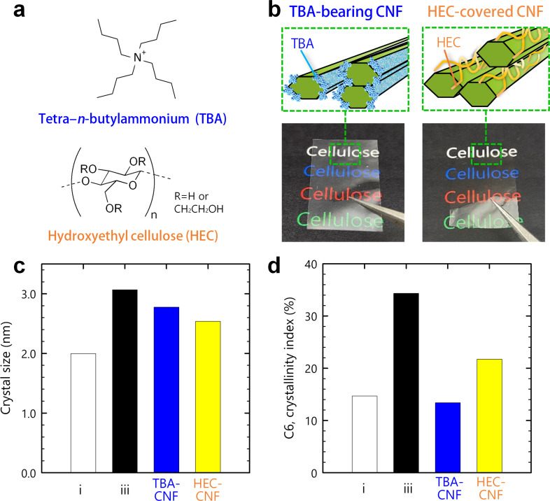
The contribution of the inter‐CNF interactions to the recovery of crystallinity was investigated in more detail using two additional surface‐modified CNFs (Figure 2 a,b): hydrophobic CNFs bearing bulky tetra‐n‐butylammonium (TBA) as the counter ion of the surface carboxy group; [20] and polymer‐covered CNFs adsorbing an amorphous, hydroxyethyl cellulose (HEC) by ca. 10 % w/w. [21] The adsorption of 10 % roughly corresponds to two HEC molecules per single CNF. These two CNF dispersions were assembled into transparent dry sheets through the same drying process as adopted in the preparation of samples ii and iii.
Figure 2.
Contribution of the inter‐CNF interactions. a) Chemical structures of TBA and HEC. b) Schematics of the TBA‐bearing and HEC‐covered CNFs, and appearances of the samples. c) Crystal sizes and d) crystallinity indices of the C6 carbon atoms of samples i and iii, and the TBA‐bearing and HEC‐covered CNFs.
The TBA‐bearing CNFs exhibited a significant recovery of the (2 0 0) crystal size (Figures 2 c and S9), whereas their crystallinity index stayed as low as 14 % (Figure 2 d). These results provided a deeper understanding of the recovery of crystallinity. The TBA ions are coupled with carboxy groups localized on the hydrophilic (1 1 0) and (1 −1 0) surfaces (see inset in Figure 1 a), such that the hydrophobic (2 0 0) surface is exposed. Thus, the recovery of the crystal size indicated that TBA‐bearing CNFs were stacked on the exposed (2 0 0) plane. Meanwhile, the low crystallinity index indicated that the inter‐CNF hydrogen bonds between the hydrophilic surfaces were inhibited by the bulky TBA ions. The HEC‐covered CNFs showed different behaviors, in that both the crystal size and crystallinity index slightly increased (Figure 2 c,d). HEC is amphiphilic, such that the entire CNF surfaces are sparsely covered with HEC at a CNF/HEC ratio of 9:1. [21] The results in Figure 2 c,d for the HEC‐covered CNFs were thus attributed to “partially‐blocked” inter‐CNF interactions.
These results supported that the inter‐CNF interactions, or the inter‐CNF (2 0 0) stacking and hydrogen bonding, were dominant in the recovery of crystallinity. The recovery of crystallinity by such CNF coupling may be essentially the same phenomenon as the “co‐crystallization” or “twinning” of adjacent crystallites within a pulp fiber, proposed by Newman et al.[ 22 , 23 ]
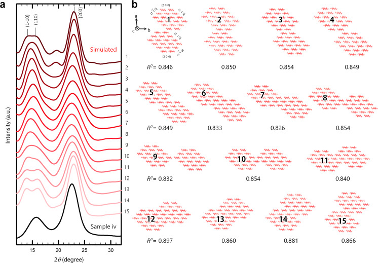
To assess the major configuration of CNFs in the interactions, an XRD profile of sample iv was compared with simulated profiles of possible inter‐CNF configurations (Figures 3 and S10). The experimental profile was obtained by azimuthally integrating an XRD diagram of a sample iv sheet set parallel to the beam. We assumed no specific orientation of the crystal planes to the sheet surface by considering: 1) the similarity of the experimental profile in Figure 3 with that obtained by the reflection method for sample iv in Figure 1 a, and 2) the twisting structure of the CNFs around the crystallographic c axis.[ 24 , 25 , 26 ]
Figure 3.
Simulation. a) Comparison of the XRD profile of sample iv with the simulated profiles of b) the possible inter‐CNF configurations #1–15. The CNFs were assumed to assemble parallel to one another along the crystallographic c axis.
In the simulation, the structure of the single CNFs was assumed to be composed of 18 cellulose chains with a stacking mode of 2/3/4/4/3/2, based on previous reports on the morphological analyses of single CNFs.[ 11 , 27 ] This 18‐chain model has flat two‐molecule‐wide (2 0 0) surfaces, enabling the CNFs to stably stack on the (2 0 0) plane (see the results for TBA‐bearing CNFs in Figure 2). As shown in Figure 3, the CNFs assembled parallel to one another along the c axis. Simulations of antiparallel assembly are shown in Figure S10. Coupling of only two CNFs was simulated here for simplicity but the reality should be more complex.
The highest R 2 value (0.897) was obtained for configuration #12, where the modelled CNFs coupled facing their (1 1 0) surfaces. [28] This configuration allows the CNFs to form inter‐CNF hydrogen bonds, explaining the recovery of the crystal size and crystallinity index for sample iv. In addition, the (1 1 0) plane has a larger surface free energy than the other planes. [29] Thus, the CNF coupling for configuration #12 reduces the free energy in the system to a greater extent and is the most stable of the possible inter‐CNF configurations. The XRD profile of the starting pulp (Figure 1 a) also showed the best fit (R 2 =0.883) configuration #12. A similar result was obtained for the antiparallel assembly shown in Figure S10; the best fit (R 2 =0.875) was achieved at a configuration that significantly reduced the (1 1 0) surface. In the antiparallel assembly, there existed no configuration where the CNFs coupled by facing the same crystal plane.
Configuration #7 matched the experimental profile in terms of peak shape, especially at lower angles of ca. 15°. However, its coefficient of correlation, R 2 (0.826), was the lowest (see Methods for the R 2 calculation). This gap was because the intensity ratio of the (2 0 0) plane and combined (1 −1 0)/(1 1 0) peaks in the simulation was significantly different from the corresponding ratio for the experimental profile. On closer inspection, the position of the combined (1 −1 0)/(1 1 0) peak in the simulation was also shifted by ca. 1° from the experimental peak.
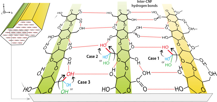
The recovery of the (2 0 0) crystal size was easily interpreted as the phase extension of the (2 0 0) plane by CNF assembly. However, the mechanism for the recovery of crystallinity index must be considered. In Figure 1 d, the C4‐ and C6‐derived crystallinity indices were coordinated and recovered from the lowest degrees of 15–20 % (sample i) up to ca. 40 % (sample iv). Considering that most of the C6 hydroxy groups exposed on the CNF surface were converted to carboxy groups, the recovery of crystallinity index was interpreted to result from conformational changes of not only the residual surface C6 hydroxy group but also the interior of each CNF structure via inter‐CNF hydrogen bonding.
Figure 4 illustrates a hypothesis for the conformational changes induced by the inter‐CNF hydrogen bonding. Three cases were assumed based on the hydrogen‐bonding mode in the cellulose I type structure. [10] In case 1, the residual surface C6 hydroxy groups take the tg conformation from other noncrystalline states (gt or gg, see the recovery of crystallinity discussion above). This change is the most plausible, but the maximum contribution to the recovery of crystallinity index is estimated to be ca. 10 %, which is insufficient for explaining the recovery of ca. 25 %. Cases 2 and 3 describe the conformational changes occurring at the interior of each CNF structure. In case 2, the C6 hydroxy groups in the surface molecules of each CNF facing inside adopt the tg conformation. In case 3, the C6 hydroxy groups in the interior molecules facing the surface molecules adopt the tg conformation. These two cases were assumed to result from some restraint imposed on the surface molecules via the inter‐CNF hydrogen bonding.
Figure 4.
A hypothesis for the conformational changes of the C6 carbon atoms induced by the inter‐CNF hydrogen bonding.
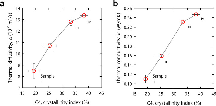
The recovery of crystallinity was expected to improve the bulk properties of the CNF structures. Figure 5 shows the thermal diffusivity, α, and conductivity, k, of samples i–iv as a function of the crystallinity index. With the recovery of crystallinity, both the diffusivity and conductivity significantly improved (see Figure S11 for the specific values of α and k divided by their bulk densities, showing the same trend). This trend is reasonable because heat transfers in a solid via phonon propagation. The phonon is an elastic wave and is often scattered at the grain boundary in a particle assembly. The recovery of crystallinity was caused by the inter‐CNF interactions, which reduced the grain boundary and facilitated phonon propagation.
Figure 5.
Contribution to bulk properties. a) Thermal diffusivity and b) conductivity of samples i–iv as a function of the crystallinity index of the C4 carbon atoms. Each plot shows the mean values with standard deviations estimated using three sets of samples i–iv.
Conclusion
Enhancing the interaction between CNFs or a‐few‐nanometer‐wide fibrillar crystallites of cellulose resulted in the coupling of multiple crystallites into single fusion crystals in a bulk aggregate without passing through a melting or dissolving state. The interaction was enhanced by the following steps: starting from a nematic liquid‐crystalline dispersion where the CNFs were uniaxially oriented in places, forming a dense aggregate by condensation, and enabling the CNFs to bind with one another via hydrogen bonds at the grain boundary. These steps induced the conformational change of the constituent carbon atoms of the CNFs to be crystalline, and the phase extension of the crystal planes occurred. Accordingly, the lowered crystallinity of the CNFs, which was previously considered irreversible from an energetic point of view, was recovered, and thermal energy transfer in the aggregate was significantly improved. CNFs have recently been produced in industrial settings, for example, ca. 1000 ton capacity in Japan in 2020, [30] and this finding will contribute to the building of the technical bases for exploiting the potential of CNFs in bulk materials.
Other fibrillar crystallites of crab shell chitin also showed a similar fusion phenomenon through the enhancement of their inter‐crystallite interactions in the solid state. The implication is that such crystallite fusion naturally occurs in biological structures with network skeletons of aggregated fibrillar crystallites.
Conflict of interest
The authors declare no conflict of interest.
Supporting information
As a service to our authors and readers, this journal provides supporting information supplied by the authors. Such materials are peer reviewed and may be re‐organized for online delivery, but are not copy‐edited or typeset. Technical support issues arising from supporting information (other than missing files) should be addressed to the authors.
Supporting Information
Acknowledgements
This research was partially supported by the JST‐Mirai R&D Program (JPMJMI17ED), JSPS Grant‐in‐Aids for Scientific Research (18K14501; 20J12793; 20K15567; 21H04733), a PHOENIX Grant‐in‐Aid, and the Research Program for Next Generation Young Scientists of “Network Joint Research Center for Materials and Devices: Dynamic Alliance for Open Innovation Bridging Human, Environment and Materials” (20205012). We also thank Prof. Tomoya Imai at Kyoto University in Japan for fruitful discussion about the XRD analyses.
K. Daicho, K. Kobayashi, S. Fujisawa, T. Saito, Angew. Chem. Int. Ed. 2021, 60, 24630.
A previous version of this manuscript has been deposited on a preprint server (https://doi.org/10.21203/rs.3.rs‐518217/v4).
Contributor Information
Dr. Kazuho Daicho, Email: daichok@g.ecc.u-tokyo.ac.jp.
Prof. Tsuguyuki Saito, Email: saitot@g.ecc.u-tokyo.ac.jp.
References
- 1. Ashby M. F., Shercliff H., Cebon D., Materials: Engineering, Science Processing and Design, Butterworth-Heinemann, Oxford, 2018. [Google Scholar]
- 2. Shan Z., Stach E. A., Wiezorek J. M. K., Knapp J. A., Follstaedt D. M., Mao S. X., Science 2004, 305, 654–657. [DOI] [PubMed] [Google Scholar]
- 3. Qian X., Zhou J., Chen G., Nat. Mater. 2021, 20, 1188–1202. [DOI] [PubMed] [Google Scholar]
- 4. Huang P. Y., Ruiz-Vargas C. S., van der Zande A. M., Whitney W. S., Levendorf M. P., Kevek J. W., Garg S., Alden J. S., Hustedt C. J., Zhu Y., Park J., McEuen P. L., Muller D. A., Nature 2011, 469, 389–392. [DOI] [PubMed] [Google Scholar]
- 5. Podsiadlo P., Kaushik A. K., Arruda E. M., Waas A. M., Shim B. S., Xu J., Nandivada H., Pumplin B. G., Lahann J., Ramamoorthy A., Kotov N. A., Science 2007, 318, 80–83. [DOI] [PubMed] [Google Scholar]
- 6. Hou Y., Guan Q.-F., Xia J., Ling Z.-C., He Z., Han Z.-M., Yang H.-B., Gu P., Zhu Y., Yu S.-H., ACS Nano 2021, 15, 1310–1320. [DOI] [PubMed] [Google Scholar]
- 7. Goris B., Bals S., Van den Broek W., Carbó-Argibay E., Gómez-Graña S., Liz-Marzán L. M., Van Tendeloo G., Nat. Mater. 2012, 11, 930–935. [DOI] [PubMed] [Google Scholar]
- 8. Moon R. J., Martini A., Nairn J., Simonsen J., Youngblood J., Chem. Soc. Rev. 2011, 40, 3941–3994. [DOI] [PubMed] [Google Scholar]
- 9. Cosgrove D. J., Nat. Rev. Mol. Cell Biol. 2005, 6, 850–861. [DOI] [PubMed] [Google Scholar]
- 10. Nishiyama Y., Langan P., Chanzy H., J. Am. Chem. Soc. 2002, 124, 9074–9082. [DOI] [PubMed] [Google Scholar]
- 11. Daicho K., Saito T., Fujisawa S., Isogai A., ACS Appl. Nano Mater. 2018, 1, 5774–5785. [Google Scholar]
- 12. Fernandes A. N., Thomas L. H., Altaner C. M., Callow P., Forsyth V. T., Apperley D. C., Kennedy C. J., Jarvis M. C., Proc. Natl. Acad. Sci. USA 2011, 108, E1195-1203. [DOI] [PMC free article] [PubMed] [Google Scholar]
- 13. French A. D., Pérez S., Bulone V., Rosenau T., Gray D. in Encyclopedia of Polymer Science and Technology, Wiley, Hoboken, 2018, pp. 1–69. [Google Scholar]
- 14. Saito T., Nishiyama Y., Putaux J., Vignon M., Isogai A., Biomacromolecules 2006, 7, 1687–1691. [DOI] [PubMed] [Google Scholar]
- 15. Saito T., Uematsu T., Kimura S., Enomae T., Isogai A., Soft Matter 2011, 7, 8804–8809. [Google Scholar]
- 16. Nemoto J., Saito T., Isogai A., ACS Appl. Mater. Interfaces 2015, 7, 19809–19815. [DOI] [PubMed] [Google Scholar]
- 17. Zhao M., Ansari F., Takeuchi M., Shimizu M., Saito T., Berglund L., Isogai A., Nanoscale Horiz. 2018, 3, 28–34. [DOI] [PubMed] [Google Scholar]
- 18. Shimizu M., Saito T., Isogai A., J. Membr. Sci. 2016, 500, 1–7. [Google Scholar]
- 19. Huang S., Makarem M., Kiemle S. N., Zheng Y., He X., Ye D., Gomez E. W., Gomez E. D., Cosgrove D. J., Kim S. H., Carbohydr. Polym. 2018, 197, 337–348. [DOI] [PubMed] [Google Scholar]
- 20. Shimizu M., Saito T., Isogai A., Biomacromolecules 2014, 15, 1904–1909. [DOI] [PubMed] [Google Scholar]
- 21. Zhou Q., Malm E., Nilsson H., Larsson P. T., Iversen T., Berglund L. A., Bulone V., Soft Matter 2009, 5, 4124–4130. [Google Scholar]
- 22. Newman R. H., Cellulose 2004, 11, 45–52. [Google Scholar]
- 23. Newman R. H., Hill S. J., Harris P. J., Plant Physiol. 2013, 163, 1558–1567. [DOI] [PMC free article] [PubMed] [Google Scholar]
- 24. Willhammar T., Daicho K., Johnstone D. N., Kobayashi K., Liu Y., Midgley P. A., Bergström L., Saito T., ACS Nano 2021, 15, 2730–2737. [DOI] [PMC free article] [PubMed] [Google Scholar]
- 25. Ogawa Y., Nanoscale 2019, 11, 21767–21774. [DOI] [PubMed] [Google Scholar]
- 26. Nyström G., Arcari M., Adamcik J., Usov I., Mezzenga R., ACS Nano 2018, 12, 5141–5148. [DOI] [PubMed] [Google Scholar]
- 27. Song B., Zhao S., Shen W., Collings C., Ding S.-Y., Front. Plant Sci. 2020, 11, DOI: 10.3389/fpls.2020.00479. [DOI] [PMC free article] [PubMed] [Google Scholar]
- 28. Rosén T., He H., Wang R., Zhan C., Chodankar S., Fall A., Aulin C., Larsson P. T., Lindström T., Hsiao B. S., ACS Nano 2020, 14, 16743–16754. [DOI] [PMC free article] [PubMed] [Google Scholar]
- 29. Oehme D. P., Doblin M. S., Wagner J., Bacic A., Downton M. T., Gidley M. J., Cellulose 2015, 22, 3501–3520. [Google Scholar]
- 30.See, for example, the website of Nanocellulose Japan, Available from: https://www.nanocellulosejapan.com/.
Associated Data
This section collects any data citations, data availability statements, or supplementary materials included in this article.
Supplementary Materials
As a service to our authors and readers, this journal provides supporting information supplied by the authors. Such materials are peer reviewed and may be re‐organized for online delivery, but are not copy‐edited or typeset. Technical support issues arising from supporting information (other than missing files) should be addressed to the authors.
Supporting Information


