

Abstract
Objective:
To evaluate whether overloading of teeth can be avoided by utilizing aligners with reduced thicknesses of 0.4 mm or 0.3 mm.
Materials and Methods:
The experimental setup included an acrylic maxillary jaw model with tooth 11 separated and fixed via a 3-D force-moment transducer to a hexapod for experimental movement. Aligners tested were fabricated on duplicate stone models using commercially available polyethylene terephthalate glycol (PET-G) foils with thicknesses between 0.5 and 0.75 mm, and novel 0.4-mm- and 0.3-mm-thick foils. With the test aligner seated, 11 was bodily displaced in a labiopalatal direction in the range of ±0.25 mm while all six force-and-moment components exerted on this tooth were registered.
Results:
With the thinnest commercially available 0.5-mm aligner, median forces of −7.89 N and 8.37 N were measured for the maximum 0.25-mm movement of 11 in a labial and palatal direction, respectively. In comparison, force values were 35% and 71% lower for the novel aligners with a thickness of 0.4 mm and 0.3 mm, respectively.
Conclusions:
Novel “leveling” aligners with reduced thickness may reduce overloading of individual teeth during aligner therapy. Due to form instability of 0.3-mm aligners, we suggest a novel sequence of 0.4–0.5–0.75 mm for aligner systems using several foil thicknesses for load graduation within single setup steps. This would combine low stiffness of the initial aligner and relatively constant load increases throughout the treatment.
Keywords: Orthodontic aligner, Force, Overloading, Aligner thickness, Aligner sequence
INTRODUCTION
During the past decade, aligners have been established as an alternative removable appliance for correction of tooth malposition. Originally, Kesling introduced aligners as a supplementary treatment for finishing orthodontic treatment.1 Since then, several technical improvements in aligners have been developed and evaluated. A significant step forward was the introduction of different thermoforming techniques using plastic sheets to fabricate the appliance in an efficient manner.2 Later improvements led to a force reduction by using double-layered foils,3 using more flexible materials (eg, polyethylene vinyl acetate or polyurethane), or implementing pressure points in the aligner.4 These modifications aimed mainly to increase the versatility of the appliance. Toward the end of the 20th century, two novel aligner systems were developed and introduced to the orthodontic field allowing a larger range of tooth movement. The Invisalign system5 (Align Technology, Santa Clara, Calif) is based on small setup increments ranging between 0.1–0.2 mm and uses one aligner for each setup with all subsequent aligners having uniform material characteristics. In contrast, the Clear-Aligner system (Scheu Dental GmbH, Iserlohn, Germany) incorporates larger setup increments of 0.5 mm for the first setup and up to 1.0 mm for all consequent steps, which requires the fabrication of several aligners with a different load deflection behavior within each setup step.5,6 The latter is realized by sequentially increasing the thickness of the plastic foil used for thermoforming from 0.5 mm to 0.625 mm and 0.75 mm.
Reviewing the currently available literature revealed that such specific selection of foil thickness could not be based on meaningful clinical or experimental data. For instance, in the two published in vivo studies on force application by aligners, either pressure-indicating foils placed between the aligner and the tooth of interest7 or strain gauges for determining the von Mises strains8 were used. The main limitations of such methods with respect to determining the force system applied to a single tooth are related to the fact that such measurements are very localized and are restricted to certain regions of the aligner and tooth, respectively, which does not account for the complex and uneven aligner-induced pressure distribution on the tooth surface. In vitro studies on mechanical aligner characteristics have included three-point bending of flat aligner specimens. One of these investigations reported 7.4%–25.1% thickness reductions after thermoforming,9 and another concluded that relative tooth displacements in the setup below 0.5 mm would prevent excessive force application during aligner therapy at least for certain plastic materials.10 Although such study design allows a basic comparison between the various plastic materials, it must be noted that results cannot be transferred to the clinical situation because of the simplified specimen geometry that ignores relevant mechanical effects such as regional reinforcement of the plastic material due to thermoforming on dental models.11,12 The latter has been considered in later investigations examining force-and-moment application of aligners thermoformed on dentition models. Results clearly indicated that the teeth are overloaded when following the recommendations regarding tooth displacements in the setup and aligner materials.11,13–15 For instance, force values of up to eight times those recommended for tipping a maxillary central incisor were recorded for the thinnest commercially available aligner material with a thickness of only 0.5 mm.15 It might be speculated that such overloading of single teeth by aligners might increase the risk of root resorption. However, there is only one in vivo study published concluding that the risk of root resorption is similar for treatment with aligners and fixed appliances.16
Regardless of the insufficient clinical evidence for an increased root resorption risk of aligners, interrelations between orthodontic force magnitude and amount of resorption are generally acknowledged and supported by several in vivo studies.17 Hence, aligners' overloading teeth should be avoided. Principally, this can be achieved either by reducing the movement increments in each setup or by using thinner and less stiff aligner materials. In the current study, we pursued the second approach and evaluated the forces and moments applied by novel aligner thicknesses of 0.4 mm and 0.3 mm during the labiopalatal bodily movement of a maxillary central incisor. A further aspect of this biomechanical study was evaluating the moment-to-force (M/F) ratio to determine the type of movement associated with aligners of different thicknesses. Moreover, we evaluated the form stability of the novel thinner materials after thermoforming and repeated seating on and removal from the test model.
MATERIALS AND METHODS
Test Apparatus
The test apparatus (Figure 1) consisted of a maxillary Frasaco model (Frasaco GmbH, Tettnang, Germany) with a separated maxillary central incisor (tooth 11) mounted on a 3-D force-and-moment sensor (Nano 17 Sensor, ATI Industrial Automation, Apex, Markham, Ontario, Canada). This design enabled recording all the forces and moments applied during the experimental tooth movement. The experimental simulation of tooth displacement was achieved by using a hexapod that allowed simulating different malpositions of the measurement tooth (Figure 1). Occlusal forces were simulated by a horseshoe-shaped opposite-jaw piece lined with silicone material to prevent the aligners' being dislodged during the experiments. The occlusal forces were maintained at a level of 30 N by adjusting coil springs and tightening screws (Figure 1). The whole test apparatus was enclosed in a climate chamber to maintain a temperature of 37°C.
Figure 1.

Detailed view of the test apparatus showing the tooth mounted on the 3-D force-moment sensor. A horseshoe, opposite-jaw piece with silicone underlining was used for simulating occlusal forces and securing the aligners on the maxillary model during the tests.
Aligner Materials and Fabrication
Aligners made from polyethylene terephthalate glycol (PET-G) foils (Duran, Scheu Dental) were examined. They were fabricated on duplicates of the original Frasaco model, that is, before separating the measurement tooth. Duplicates were made using a type 4 dental cast stone (Fujirock, GC Europe NV, Leuven, Belgium). Two lines were drawn on each duplicate model at distances of 10 mm and 3 mm below the gingival margins, indicating the model embedding depth during the thermoforming process and the gingival extension of the aligners, respectively. A spacer foil (Isofolan, Scheu Dental) was thermoformed on the models before the test aligners were made according to the manufacturer's recommendation. To account for possible variations in the thermoforming process, three aligners were fabricated from each foil thickness, that is, the commercially available original thicknesses of 0.5 mm, 0.625 mm, and 0.75 mm, as well as the reduced thicknesses of 0.4 mm and 0.3 mm. Directly after thermoforming, the line on the duplicate models marking the aligner extension was transferred to the aligner, which was then cut to this level.
Test Procedure
Before the experiments, the aligners were stored in the climate chamber at 37°C for at least 30 minutes. They were then moistened with artificial saliva (Glandosane, Cell Pharm, Bad Vilbel, Germany) and seated on the test model with the measurement tooth in its original position. The horseshoe plate was then positioned and the screws were tightened to the desired force (30 N). The measurement tooth was then bodily displaced in a labiopalatal direction to a maximum of ±0.25 mm in 0.01-mm steps.
Data Analysis
Data analysis was performed using special algorithms programmed in Matlab (The Math Works Inc, Natick, Mass). Measured 3-D force-and-moment values were all referred to the estimated center of resistance of the measurement tooth. For each aligner, we characterized its stiffness with respect to labial and palatal displacements of 11 by calculating individual stiffness values for each pair of subsequent data points on the labiopalatal force (Fy) curves. The quasilinear behavior of these force curves (Figure 2) allowed for calculating one average stiffness value per curve and displacement direction, considering all individual stiffness values between the corresponding 5th and 95th percentiles. Additionally, M/F ratios were calculated for each aligner and both displacement directions to determine the resulting type of tooth movement. These M/F ratios were also referred to the center of resistance of the measurement tooth, which means that an M/F ratio of 0 mm would indicate a purely bodily tooth movement.
Figure 2.

Example of stiffness determination for a 0.5-mm-thick Duran aligner. The measurement curve shows nearly linear behavior. The dashed lines represent the calculated average stiffness of the labial and palatal displacement directions of 11.
Collected data were statistically analyzed using the software SAS 9.1.3 (SAS Institute Inc, Cary, NC). Descriptive analysis included calculating the maximum, minimum, median, and interquartile range values of the determined forces, moments, stiffness values, and M/F ratios separately for each displacement direction and aligner thickness. The aligner stiffness values were further analyzed using the Kruskal-Wallis test to evaluate differences between displacement directions and aligner thicknesses. Furthermore, the regularity of stiffness increases within different aligner sequences was characterized by calculating Pearson correlation coefficients (ρ).
RESULTS
Forces and Moments
Figure 3 exemplifies the six force-and-moment components applied by a 0.5-mm aligner during the ±0.25-mm labiopalatal displacement of 11. As expected, the curves revealed maximum values for the Fy and the corresponding moment for labiopalatal crown tipping. However, collateral forces and moments can also be observed. A quasilinear increase in Fys was observed throughout the whole displacement range. In general, curves for all measurements showed a similar trend.
Figure 3.

Example of 3-D force (Fx, Fy, Fz)- and-moment (Mx, My, Mz) values measured for a 0.5-mm Duran aligner during ±0.25-mm labiopalatal bodily movement of the measurement tooth. Negative displacement values represent palatal movement direction. Force-and-moment values are referred to the estimated center of resistance of the measurement tooth.
The median Fys measured for the 0.5-mm aligner were −7.89 N (IQR = 1.15) for the 0.25-mm labial displacement and 8.37 N (IQR = 0.83) for the 0.25-mm palatal displacement. The corresponding forces measured with the novel 0.4-mm and 0.3-mm leveling aligners were −5.09 N (IQR = 0.26) and −2.50 (IQR = 1.15) for the labial, as well as 5.41 N (IQR = 1.36) and 2.24 N (IQR = 1.29) for the palatal displacement, respectively (Table 1). These forces correspond to an average reduction in both directions of 35% (0.4-mm aligner) and 71% (0.3-mm aligner).
Table 1.
Labio-Palatal Forces, Moments, and M/F Ratios Measured at the Maximum Labial and Palatal Displacement of the Measurement Tooth

Aligner Stiffness
Stiffness values for the various aligner thicknesses and displacement directions are given in Table 2 and illustrated in Figure 4. Generally, the aligner stiffness showed an increase with an increasing aligner thickness (Kruskal-Wallis test; P < .05) and was higher for the palatal than for the labial displacement of 11 (Kruskal-Wallis test; P < .05). Moreover, the Pearson correlation test revealed a relatively high and significant correlation (ρ) between the stiffness values and aligner thickness in both the labial (ρ = 0.92) and palatal direction (ρ = 0.90). As expected, the highest stiffness was observed for the thickest (0.7-mm) aligner, with median values of 37.38 N/mm (labial direction) and 43.88 N/mm (palatal direction). Stiffness increases between the 0.5-mm and 0.625-mm aligners, as well as between the 0.625-mm and 0.75-mm aligners, were relatively small, with average values ranging between 5% and 8%, respectively (Table 2). According to the Pearson correlation coefficients, stiffness increments for the thickness sequences of either 0.4-mm/0.5-mm/0.75-mm (P = .79) or 0.3-mm/0.5-mm/0.75-mm (P = .89) were more regular than the currently recommended sequence of 0.5-mm/0.625-mm/0.75-mm (P = .60) (Table 3).
Table 2.
Median Aligner Stiffness in Labial and Palatal Directions Calculated From the Load-Deflection Curves of the Various Aligners

Figure 4.

Box plot representing aligner stiffness values for labial and palatal bodily displacement of 11. Color-coded thickness values represent the original foil thicknesses before thermoforming. Lines inside boxes represent the median values. Cross marks outside the boxes represent outliers.
Table 3.
Comparison of Pearson Correlation Coefficients for the Current (0.5/0.625 mm and 0.75 mm) and the Two Possible Novel Sequences

Moment-to-Force Ratios
The calculated M/F ratios for the various aligners ranged between −11.42 and −12.30 for the labial movement direction. The corresponding range for the palatal direction was −8.15 to −9.98 mm (Table 1).
Form Stability of the Novel Thinner Aligners
The thinnest (0.3-mm) aligners showed insufficient form stability after thermoforming. Deformation occurred mainly at the gingival aligner margins in the anterior region (Figure 5) and were caused by manual aligner seating and removal from the Frasaco model. The 0.4-mm-thick aligners, in contrast, showed sufficient form stability.
Figure 5.
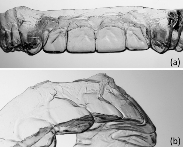
Frontal (a) and tilted (b) view of a 0.3-mm-thick aligner after thermoforming. In particular, the thin areas below the front teeth were deformed during removal from the plaster model.
DISCUSSION
Principally, there are two possible approaches to reduce the forces applied by aligners along the treatment course, either by implementing smaller tooth displacements in each setup—resulting in more treatment steps and higher laboratory costs—or by using thinner and less stiff aligners, while maintaining the current tooth displacement recommendation of a of 0.5-mm minimum.15 In this study, we explored the second approach by investigating the biomechanical behavior of novel aligners with a reduced thickness of 0.4 mm and 0.3 mm, respectively, and comparing the results with the commercially available thinnest aligners having a thickness of 0.5 mm. During our experiment, the selected maxillary right central incisor was bodily displaced by ±0.25 mm. We estimate that this value approximately corresponds to the suggested relative tooth displacement within single setup steps of 0.5 mm, because in the clinical situation, the elasticity of the periodontal ligaments of both displaced and anchorage teeth leads to smaller relative tooth displacements than those in the setup model.15 Our results indicate that, even with the thinnest commercially available 0.5-mm aligner, median forces of −7.89 N for the labial and 8.37 N for the palatal displacement would be applied to a maxillary central, resulting in significant overloading of its periodontal structures. In view of this, it seems a remarkable finding of the current study that these forces can be significantly reduced by 35% and 71% when using the novel PET-G foils with a thickness of 0.4 and 0.3 mm, respectively. Hence, using thinner aligners might be an efficient approach for reducing the risk of root resorption during aligner therapy, although this hypothesis is yet to be proven by clinical studies.
When compared with similar previous studies, our study determined higher forces and moments for the same aligner thicknesses.11,13,15 This difference might be explained by use of the opposite-jaw-simulating device in the current study that prevented dislodgment of the aligner from the model.15 A further interesting finding was the minimal average stiffness difference between the 0.5-mm and 0.625-mm (5%) as well as between the 0.625-mm and 0.75-mm (8%) aligner, which means that the 0.625-mm aligner could be omitted from the current aligner prescription without diminishing the efficiency of treatment. Additionally, because of the form instability of the 0.3-mm aligner, it can be concluded that PET-G aligners of this thickness are not suitable for clinical use. These findings support the suggestion of using a novel aligner sequence of 0.4, 0.5, and 0.75 mm. This sequence would ensure a relatively low initial force application, followed by a gradual and nearly uniform increase in aligner stiffness within each setup (Table 2), which is also demonstrated by the high Pearson correlation coefficient (ρ = 0.79). Further investigations are planned to determine stiffness increments and mechanical characteristics of other aligner systems.
A further objective of this biomechanical study was to evaluate the capability of aligners to induce bodily tooth movement by assessing the M/F ratio of each aligner thickness and both displacement directions of 11. It must be noted that bodily movement would require an M/F ratio of 0 mm when force-and-moment components are referred to the center of resistance of the tooth. The M/F ratios determined for the examined aligners ranged between −8.15 and −9.98 mm (palatal direction) and −11.42 and −12.30 mm (labial direction). The fact that the M/F ratios for palatal displacement are closer to zero and slightly more efficient for bodily movement agrees with the findings of a previous study and should be related to a higher force couple, creating a countertip moment.15 This is most likely due to the specific aligner contour, leading to relatively high mechanical resistance in the cervicopalatal region (Figure 6). However, with respect to the large difference in the required M/F ratio of 0 mm, it must be emphasized that even for aligning a palatally displaced maxillary incisor, aligners without any modifications such as specific pressure points or stiffer cervical regions do not seem to be efficient for bodily tooth movement.18 Furthermore, the forces and moments generated by the aligner are significantly influenced by the direction and type of tooth displacement in the setup as well as the morphology of the tooth and the location of its center of resistance. These aspects have also to be considered when transferring the results of this in vitro study to specific clinical situations.
Figure 6.

Schematic explanation of the bodily movement capacity of an aligner. This capacity is related to its ability to generate both a countertipping force couple and moment. Its magnitude depends on the smallest contact force component. The tight curvature at the incisal edge reinforces the aligner, leading to relatively high incisal contact forces (Fi) for both displacement directions. In contrast, the cervical contact force (Fc) is higher for palatal tooth displacement (left) than for labial displacement (right). This is due to the specific aligner geometry leading to reinforcement in the cervicopalatal region.
With respect to the form stability of the novel aligner foils, it was found that, at least during our experiment, the 0.4-mm aligners possessed reasonable stability. In contrast, the 0.3-mm aligners showed a higher deformation rate and seem, therefore, not suitable for clinical application. However, further studies are needed to develop a full picture of the clinical suitability and ease of handling of the novel thinner materials.
CONCLUSIONS
A considerable amount of force reduction can be achieved by utilizing the novel PET-G leveling aligners with thicknesses of 0.4 or 0.3 mm, which might contribute to reducing the risk of tooth overloading and root resorption.
In contrast to the 0.4-mm aligners, the 0.3-mm aligners showed considerable form instability during experimental handling, rendering them unsuitable for clinical application.
The findings of this study suggest a modification of the aligner sequence, including 0.4-mm, 0.5-mm, and 0.75-mm PET-G foils. This sequence would combine low initial stiffness with an almost steady load increase within each treatment step; clinical studies are required before recommending this sequence as a therapeutic standard.
The M/F ratios determined in this study indicate that, for aligners without specific modifications, bodily movement of maxillary central incisors in the labiopalatal direction is impossible to achieve.
ACKNOWLEDGMENTS
This study was funded by Scheu Dental GmbH, Germany, which included the supplement of the tested PET-G foils and the newly developed and thinner 0.3-mm and 0.4-mm thick materials.
REFERENCES
- 1.Kesling H. The philosophy of the tooth positioning appliance. Am J Orthod Oral Surg. 1945;31:297–304. [Google Scholar]
- 2.Nahoum HI. The vacuum formed dental contour appliance. New York J Dent. 1964;9:385–90. [Google Scholar]
- 3.Yoshii O, Pohl M. The Osamu retainer and its indications. Am J Orthod Dentofacial Orthop. 1995;107:457. [Google Scholar]
- 4.Ponitz RJ. Invisible retainers. Am J Orthod. 1971;59:266–272. doi: 10.1016/0002-9416(71)90099-6. [DOI] [PubMed] [Google Scholar]
- 5.Boyd RL, Miller RJ, Vlaskalic V. The Invisalign system in adult orthodontics: mild crowding and space closure cases. J Clin Orthod. 2000;34:203–212. [Google Scholar]
- 6.Kim T, Echarri P. Clear aligner: an efficient, esthetic, and comfortable option for an adult patient. World J Orthod. 2007;8:13–18. [PubMed] [Google Scholar]
- 7.Barbagallo LJ, Shen G, Jones AS, Swain MV, Petocz P, Darendeliler MA. A novel pressure film approach for determining the force imparted by clear removable thermoplastic appliances. Ann Biomed Eng. 2008;36:335–341. doi: 10.1007/s10439-007-9424-5. [DOI] [PubMed] [Google Scholar]
- 8.Vardimon AD, Robbins D, Brosh T. In-vivo von Mises strains during Invisalign treatment. Am J Orthod Dentofacial Orthop. 2010;138:399–409. doi: 10.1016/j.ajodo.2008.11.027. [DOI] [PubMed] [Google Scholar]
- 9.Ryokawa H, Miyazaki Y, Fujishima A, Miyazaki T, Maki K. The mechanical properties of dental thermoplastic materials in a simulated intraoral environment. Orthod Waves. 2006;65:64–72. [Google Scholar]
- 10.Kwon J, Lee Y, Lim B, Lim Y. Force delivery properties of thermoplastic orthodontic materials. Am J Orthod Dentofacial Orthop. 2008;133:228–234. doi: 10.1016/j.ajodo.2006.03.034. quiz 328.e1. [DOI] [PubMed] [Google Scholar]
- 11.Hahn W, Fialka-Fricke J, Dathe H, Fricke-Zech S, Zapf A, Gruber R, et al. Initial forces generated by three types of thermoplastic appliances on an upper central incisor during tipping. Eur J Orthod. 2009;31:625–631. doi: 10.1093/ejo/cjp047. [DOI] [PubMed] [Google Scholar]
- 12.Nahoum HI. Forces and moments generated by removable thermoplastic aligners. Am J Orthod Dentofacial Orthop. 2014;146:545–546. doi: 10.1016/j.ajodo.2014.08.006. [DOI] [PubMed] [Google Scholar]
- 13.Hahn W, Dathe H, Fialka-Fricke J, Fricke-Zech S, Zapf A, Kubein-Meesenburg D, et al. Influence of thermoplastic appliance thickness on the magnitude of force delivered to a maxillary central incisor during tipping. Am J Orthod Dentofacial Orthop. 2009;136:12.e1–e7. doi: 10.1016/j.ajodo.2008.12.015. discussion 12–13. [DOI] [PubMed] [Google Scholar]
- 14.Hahn W, Zapf A, Dathe H, Fialka-Fricke J, Fricke-Zech S, Gruber R, et al. Torquing an upper central incisor with aligners—acting forces and biomechanical principles. Eur J Orthod. 2010;32:607–613. doi: 10.1093/ejo/cjq007. [DOI] [PubMed] [Google Scholar]
- 15.Elkholy F, Panchaphongsaphak T, Kilic F, Schmidt F, Lapatki BG. Forces and moments delivered by PET-G aligners to an upper central incisor for labial and palatal translation. J Orofac Orthop. 2015;76:460–475. doi: 10.1007/s00056-015-0307-3. [DOI] [PubMed] [Google Scholar]
- 16.Barbagallo LJ, Jones AS, Petocz P, Darendeliler MA. Physical properties of root cementum: Part 10. Comparison of the effects of invisible removable thermoplastic appliances with light and heavy orthodontic forces on premolar cementum. A microcomputed-tomography study. Am J Orthod Dentofacial Orthop. 2008;133:218–227. doi: 10.1016/j.ajodo.2006.01.043. [DOI] [PubMed] [Google Scholar]
- 17.Chan E, Darendeliler MA. Physical properties of root cementum: Part 5. Volumetric analysis of root resorption craters after application of light and heavy orthodontic forces. Am J Orthod Dentofacial Orthop. 2005;127:186–195. doi: 10.1016/j.ajodo.2003.11.026. [DOI] [PubMed] [Google Scholar]
- 18.Simon M, Keilig L, Schwarze J, Jung BA, Bourauel C. Forces and moments generated by removable thermoplastic aligners: incisor torque, premolar derotation, and molar distalization. Am J Orthod Dentofacial Orthop. 2014;145:728–736. doi: 10.1016/j.ajodo.2014.03.015. [DOI] [PubMed] [Google Scholar]