

Abstract
Microwire microelectrode arrays (MEAs) are implanted in the brain for recording neuron activities to study the brain function. Among various microwire materials, carbon fiber stands out due to its small diameter (5–10 μm), relatively high Young's modulus, and low electrical resistance. Microwire tips in MEAs are often sharpened to reduce the insertion force and prevent the thin microwires from buckling. Currently, carbon fiber MEAs are sharpened by either torch burning, which limits the positions of wire tips to a water bath surface plane, or electrical discharge machining, which is difficult to implement to the nonelectrically conductive carbon fiber with parylene-C insulation. A laser-based carbon fiber sharpening method proposed in this study enables the fabrication of carbon fiber MEAs with sharp tips and custom lengths. Experiments were conducted to study effects of laser input voltage and transverse speed on carbon fiber tip geometry. Results of the tip sharpness and stripped length of the insulation as well as the electrochemical impedance spectroscopy measurement at 1 kHz were evaluated and analyzed. The laser input voltage and traverse speed have demonstrated to be critical for the sharp tip, short stripped length, and low electrical impedance of the carbon fiber electrode for brain recording MEAs. A carbon fiber MEA with custom electrode lengths was fabricated to validate the laser-based approach.
1 Introduction
The human brain consists of about 86 × 106 neurons, and each neuron communicates with 7000 other neurons in average via axons through electric signals generated by Na+ and K+ ion transportation across the membrane [1]. The brain functioning mechanism is complex and understanding the mechanism is an active multidisciplinary research in which manufacturing plays an important role. Single neuron action has an 80–100 mV potential change and is only distinguishable within a 150 μm radius [2]. Recording of such single neuron activity is critical for understanding the brain function.
Brain recording methods like electro-encephalography, magneto-encephalography and functional magnetic resonance imaging (fMRI) lack the spatial and/or temporal resolution to record the single neuron activities [3,4]. Microelectrode array (MEA) implantation places the electrodes next to neurons, enabling the electrophysiological extracellular recording of single neuron firings. There are three types of MEAs: the silicon-based MEA, flexible MEA, and microwire MEA. Silicon-based MEAs, like the Michigan Probe [5] and Utah Array [6], stimulate the formation of scar tissue due to the rigidity of silicon electrodes and lead to signal loss over a few weeks after the implantation in the brain [7,8]. Flexible MEAs are built on thin (typically 4–14 μm in thickness) polyimide, which has great flexibility and biocompatibility [9,10]. However, the thin polyimide has low stiffness and requires a thick shuttling device (e.g., a 30 μm thick silicon stiffener [9] or a Tungsten-Rhenium needle of 40 μm diameter [10]) to facilitate the implantation, causing extra brain trauma, and affecting long-term recording quality.
Microwire MEAs use fine cellular-scale microwires as the recording electrodes. Microwire MEAs are made of different biocompatible materials, including 5–10 μm diameter carbon fiber [11–14] and 10–75 μm diameter metal (tungsten, stainless steel, platinum-iridium, etc.) [15–18], have been developed and implanted for recording of neuron signals in the brain. The small diameter of these microwires gives the flexibility to prevent the formation of scar tissue and enable the long-term recording (e.g., over three months using carbon fiber in Ref. [12]). Microwires in MEAs are coated by an insulation layer with only the electrode tips exposed for recording to increase the signal-to-noise ratio in neural signal measurement.
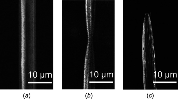
Among microwire materials, carbon fiber has the smallest diameter (under 10 μm) and a relatively high Young's modulus of 241 GPa [19], as compared to the 200 GPa of stainless steel [20] and the 160 GPa of platinum [21]. The low electrical resistivity of carbon fiber results in less noise and enables the detection of small signals without noise contamination [22]. Carbon fiber MEAs have been fabricated manually. Guitchounts et al. developed a bundle with 16 carbon fiber electrodes in 2013 (Fig. 1(a)) [13], Patel et al. fabricated a 2 × 8 carbon fiber array in 2015 (Fig. 1(b)) [11] and Massey et al. assembled a 32 carbon fiber array in 2018 (Fig. 1(c)) [23].
Fig. 1.
![Three sample carbon fiber MEAs (a) a bundle of 16 carbon fiber electrodes [13], (b) 2 × 8 carbon fiber array [11], and (c) 32 channel carbon fiber array assembled by Massey et al.](https://cdn.ncbi.nlm.nih.gov/pmc/blobs/71e1/8597551/89ae5a938c2f/jmnm-20-1041_041013_g001.jpg)
Three sample carbon fiber MEAs (a) a bundle of 16 carbon fiber electrodes [13], (b) 2 × 8 carbon fiber array [11], and (c) 32 channel carbon fiber array assembled by Massey et al.
The electrode tips in microwire MEAs are often sharpened to reduce the insertion force and avoid microwire buckling during insertion. For metal microwires, chemical etching and electrochemical machining (ECM) are two well-established methods to sharpen the microwire tip. Figure 2(a) shows the tip of a 200 μm diameter stainless steel microwire sharpened by chemical etching [31]. For microwire materials with good corrosion resistance (e.g., tungsten and platinum-iridium), ECM has been adopted for sharpening (Fig. 2(b)). However, both chemical etching and ECM cannot be applied to sharpen the tip of a carbon fiber.
Fig. 2.
![Sharp tip of metal microwire: (a) stainless steel microwire by chemical etching [31] and (b) tungsten microwire by ECM with KOH solution](https://cdn.ncbi.nlm.nih.gov/pmc/blobs/71e1/8597551/3194ed2bcf2e/jmnm-20-1041_041013_g002.jpg)
Sharp tip of metal microwire: (a) stainless steel microwire by chemical etching [31] and (b) tungsten microwire by ECM with KOH solution
Two methods are currently applied in carbon fiber tip sharpening. The first is torch burning (Fig. 3(a)) [13]. Tips of carbon fibers of an assembled array are protruded over the surface of a water bath. A torch passes over the water surface, as shown in Fig. 3(a), to burn off and sharpen the carbon fiber. This method applies only to carbon fiber MEAs with tips aligned in the same plane. MEAs with custom electrode lengths are necessary when recording neuron activities from multiple layers at different depths from the curved brain surface [24]. The second sharpening method is electrical discharge machining (EDM) (Fig. 3(c)) [25]. A tungsten cathode was brought within a few microns from the carbon fiber tip to create electrical discharges and generate a conical sharp tip [33]. For carbon fiber MEAs with electrical-insulated parylene-C coating [11,13,23], the tips are not electrical conductive for EDM sharpening.
Fig. 3.
![Carbon fiber sharpening methods and outcomes: (a) setup, (b) outcome of the torch burning method [13], (c) schematic diagram, and (d) outcome of EDM sharpening of carbon fiber [33]](https://cdn.ncbi.nlm.nih.gov/pmc/blobs/71e1/8597551/3a38ae574abe/jmnm-20-1041_041013_g003.jpg)
Carbon fiber sharpening methods and outcomes: (a) setup, (b) outcome of the torch burning method [13], (c) schematic diagram, and (d) outcome of EDM sharpening of carbon fiber [33]
This study investigated the laser sharpening of the carbon fiber tips. Using a 405 nm InGaN laser (4 DCV input), the speed of laser moving perpendicularly across the carbon fiber (denoted as speed hereafter) determines the shape of the carbon fiber tip. At 25 μm/s, the diameter of the carbon fiber was reduced, as shown in Fig. 4(b). At a slower 20 μm/s speed, the carbon fiber was cut off and left a sharp tip (Fig. 4(c)). The laser energy was absorbed by the carbon fiber, converted to the heat flux, and led to temperature rise in the carbon fiber. When the temperature exceeded 500 °C in air [26], the chemical reaction would oxidize the solid carbon into gaseous carbon dioxide. The distribution of the intensity of a laser beam with peak at the center resulted in the diameter reduction of the carbon fiber shown in Fig. 4(b). In this study, laser is studied as a controlled cutting and sharpening method for carbon fiber MEAs to create desired sharp tips.
Fig. 4.
SEM pictures of the carbon fiber with parylene-C insulation: (a) before cutting, (b) partial cutoff at 25 μm/s and 4 DCV laser input voltage, and (c) fully cutoff with sharpened conical tip at 20 μm/s and 4 DCV laser input voltage
Carbon fiber electrodes in MEAs are often insulated with parylene-C before the tip sharpening process [11,13,23]. Parylene-C is a thermoplastic material with a melting temperature of 290 °C [27]. It is lower than the oxidation temperature of carbon (above 500 °C) [26]. The heat is transferred through the carbon fiber during laser cutting to melt and remove the parylene-C insulation layer adjacent to the sharpened tip. The length of this region in the axial direction is called the stripped length (commonly 100–300 μm in the carbon fiber). This stripped length is the result of combined effects of heating and exposure time during the laser sharpening of parylene-C-coated carbon fiber. A higher laser input voltage contributes to a higher temperature in the carbon fiber and enables a faster speed and a shorter cutting time. The effect of laser input voltage and speed on stripped length is investigated in this study.
The electrical impedance of the sharpened carbon fiber electrode needs to be below 4 MΩ at 1 kHz to be categorized as a functional electrode for brain recording [13,23,28]. This electrical impedance test is performed on laser sharpened carbon fiber electrodes as a functionality test.
In this paper, the experimental setup and sharpening procedure for a carbon fiber sharpening method based on a moving laser beam are introduced. Design of experiment to explore the impact of laser input voltage and speed is presented. Experimental measurements of the carbon fiber tip geometry and parylene-C insulation stripped length are presented and discussed. Impedance test is carried out as a functionality evaluation of the carbon fiber electrodes. A carbon fiber MEA with custom electrode lengths is fabricated to validate the laser-based approach.
2 Materials and Methods
The experimental setup, procedure, and design for sharpening the carbon fiber tip as well as the electrical impedance evaluation method are presented.
2.1 Experimental Setup.
The experimental setup (Fig. 5(a)) consisted of a three-axis motion system, a laser head, a microscope camera for process monitoring and a printed circuit board (PCB) with carbon fibers. The motion system was composed of three orthogonally configured linear stages. Two horizontal linear stages (200cri-R by Siskiyou, Grants Pass, OR) were denoted as x and y. The vertical linear stage z (100cri-R by Siskiyou, Grant Pass, OR) carried the laser head and could be moved horizontally by the x and y linear stages. The positive directions of motion for linear stages x, y, and z are marked in Fig. 5(a) and denoted as positive x-, y-, and z-directions, respectively. The positioning accuracy of all three linear stages was 2 μm and the three-axis motion was coordinated through the same controller (PCI-7344 by National Instruments, Austin, TX). Both the PCB and camera were stationary. A multimode InGaN semiconductor laser (1.5 W maximum output power and 405 nm violet wavelength) made by WER (Shanghai, China) was fixed on the linear stage z and pointing down in the negative z-direction. The laser head was 12 mm in diameter and 40 mm in length. The convex lens attached to the laser head had a focal length of 100 mm. The laser beam had a 1 mm depth of focus and a 75 μm beam waist radius. It had a 1.5 W maximum power under the 5 DCV input voltage and lower input voltage can be adjusted to reduce the laser power. The multimode InGaN semiconductor lasers are widely used as engraver lasers and are of compact size, enabling their broad integration in biomedical and neuroscience research labs. This specific laser had the suitable power (1.5 W maximum) to cutoff and sharpen 6.8 μm diameter carbon fibers in this study.
Fig. 5.
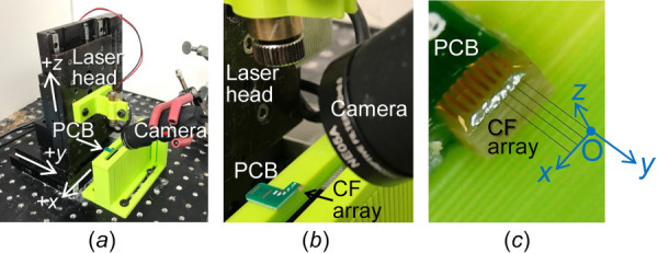
Experimental setup: (a) overview of the three-axis motion system, stationary camera and PCB, (b) close-up view of the laser head, camera and PCB, and (c) camera view of the 1 × 4 carbon fiber array on the PCB
A 1 × 4 carbon fiber array was fixed at the side of the PCB, which was stationary and located on a fixture, as shown in Fig. 5(a). The close-up view of the PCB on the fixture is shown in Fig. 5(b). The close-up view of the four carbon fibers in PCB is shown in Fig. 5(c). The 6.8 μm carbon fiber (T-650/35 3 K by Cytec Thornel, Woodland Park, NJ) had 800 nm thick parylene-C coating by chemical vapor deposition (using PDS-2010 by Specialty Coating Systems, Indianapolis, IN) for electrical insulation. All four carbon fibers on the PCB had parylene-C coating, 8.4 μm in diameter (coating included), 2 mm overhanging length, and 200 μm pitch. As shown in Fig. 5(c), these four carbon fibers were placed horizontally in the xy plane and aligned along the y-direction. The distal end of the first carbon fiber in the array was assigned as the origin, marked as point O. Four carbon fibers were accurately aligned in the xy plane with their variation in height in the z-direction less than 250 μm, which is less than a quarter of the laser depth of focus and ensures the laser cutting zone coverage of all carbon fibers.
2.2 Sharpening Procedure.
The laser was first adjusted to focus at the tip of the carbon fiber by moving linear stages x, y, and z to focus at O. During cutting and sharpening carbon fibers, the laser head was guided by two linear stages (xy) along a designed path in a horizontal plane with linear stage z remained stationary.
2.2.1 Focus of the Laser on a Carbon Fiber Tip.
When the power of the visible laser beam was sufficiently low, the carbon fiber could not be cutoff and an oval-shaped light spot, as shown in Fig. 6, was visible by the camera due to the reflection of the laser light on the parylene-C coating and the carbon fiber. In this study, 1.7 DCV was found to be the lowest input voltage for the laser to have a visible light spot and could not cutoff the carbon fiber after focusing on it for over 5 min, which was long enough to focus the laser center of focal spot at point O based on the following three steps. In step 1, linear stages x and y were moved to find the largest light spot on the carbon fiber with point O at the tip. The center of the focal spot was moved to x = 0. In step 2, the linear stage z was adjusted vertically to find the smallest light spot size on the carbon fiber. The center of the focal spot was at z = 0. In step 3, the linear stage y was moved until the length of the light spot in y-direction was equal to half of that in step 2. The center of the focal spot was moved to y = 0 and aligned with point O.
Fig. 6.
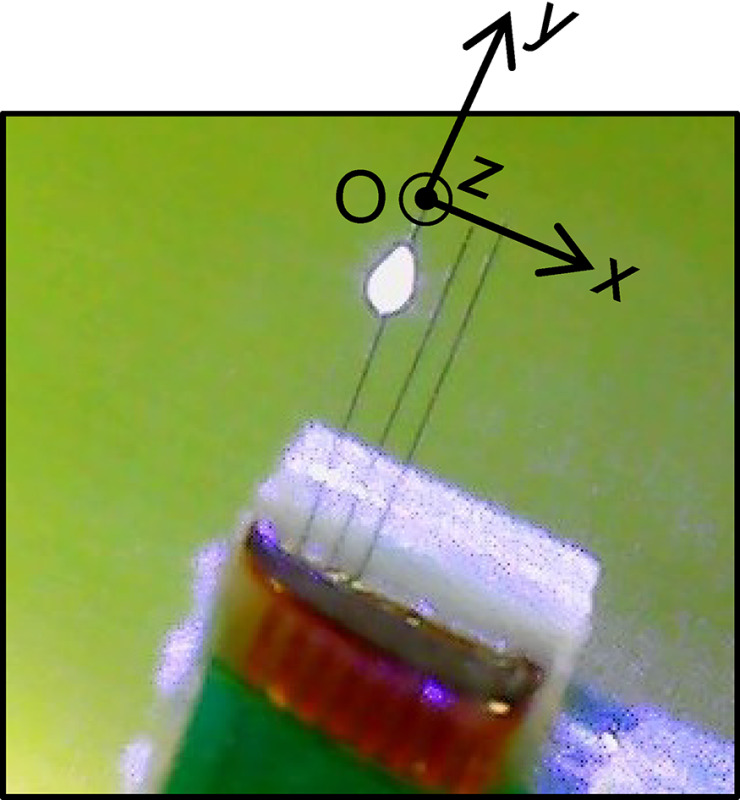
The light spot on the carbon fiber when the laser beam hit the carbon fiber
2.2.2 Cutting Paths.
Two cutting paths, denoted as path I and II, in the xy plane are shown in Fig. 7. The center of the laser focal spot was in the carbon fiber plane (z = 0) for cutting and sharpening. In path I, as shown in Fig. 7(a), the laser was moved along a straight line in the x-direction across all four carbon fibers. In path II, the laser was moved in both the x- and y-directions to fabricate an MEA with varying carbon fiber electrode lengths shown as l1, l2, l3, and l4 in Fig. 7(b). The laser moved transversely across the carbon fiber in the x-direction with its power on during cutting and sharpening. Along the y-direction, the laser was moved without power on.
Fig. 7.
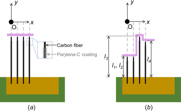
Schematic diagram of laser path: (a) path I for Experiments I and II (0.2 mm pitch between two adjacent fibers) and (b) Path II for Experiment III
2.3 Experiment Design and Measurements.
Experiments I, II, and III were conducted to study effects of laser speed and input voltage on the sharpness and stripped length of parylene-C-coated carbon fiber tips.
Experiment I identified the maximum allowable speed for the cutoff of all four carbon fibers in an array under three laser input voltage levels (2.5, 4.0, and 5.0 DCV) using Path I. A minimal thermal energy accumulation from laser is needed for the carbon fiber cutoff. Thus, there exists a maximum allowed speed under each laser input voltage level. During laser cutting, the thermoplastic parylene-C insulation on carbon fiber is partially removed. The exposed surface area affects the microelectrode impedance, which is crucial for single neuron activity recording. An electrode is defined to be functional if its 1 kHz impedance is lower than 4 MΩ [9]. Carbon fiber microelectrodes with small exposed surface area would yield high impedance (e.g., 3.9 MΩ at 1 kHz for carbon fiber with 257 μm2 exposed area in Ref. [28]) close to the 4 MΩ upper limit. Large exposed surface area leads to lower impedance but will reduce the electrode's sensitivity to single unit spikes [13,28]. In this preliminary study, the laser cutting generates a stripped length over 100 μm and an exposed area over 2000 μm2, which is larger than the approximately 700 μm2 exposed area generated by the current torch burning approach [13]. Thus, it is preferred for the laser cutting to be operated at or near the maximum allowed speed to enable the cutoff of parylene-C-coated carbon fiber with minimal parylene-C stripping. Under 5 DCV laser input voltage, Experiment I started with the laser moving in the x-direction at 30 μm/s. This speed was decreased by 2 μm/s increment until the speed with all four carbon fibers were cutoff. Another test was carried out with the speed increased by 1 μm/s. The larger speed of these two with the cutoff of all four carbon fibers was selected for 5 DCV. This procedure was repeated in tests at 4.0 and 2.5 DCV to find the laser speed enabling the cutoff of all four carbon fibers.
The largest allowable speed under each voltage found in Experiment I was utilized in Experiment II to study the effects of laser input voltage on carbon fiber tip sharpness and stripped length of parylene-C. For each laser input voltage, one cut across four carbon fibers using Path I was carried out based on the speed and laser input voltage identified in Experiment I. Micrographs of carbon fiber tips were acquired with the scanning electron microscope (SEM) (JSM-IT500HR by JEOL, Tokyo, Japan). Using the Fiji image processing package [29] in imagej (v.1.52r) [30], the tip profile, tip angle, and parylene-C-stripped length were measured based on SEM micrographs of carbon fiber tips. The diameter of bare carbon fiber without parylene-C coating is denoted as D1, as shown in Fig. 8(a). In this study, D1 was 6.8 μm. The diameter of the sharpened carbon fiber at different axial positions on the carbon fiber tip was denoted as D2 in Fig. 8(a). The conical tip profile was characterized by three axial distances, denoted as L1, L2, and L3, between the tip and the positions corresponding to D2 of 0.2D1, 0.5D1, and 0.8D1, respectively.
Fig. 8.
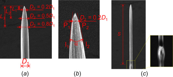
Evaluation metrics for (a) tip profile L1, L2, and L3: the distances between tip and the positions which correspond to D2 = 0.2D1, 0.5D1, and 0.8D1, (b) tip angle α, and (c) stripped length S: the distance from the tip to the end of the stripped region
For a conical carbon fiber tip, the tip angle α was measured as illustrated in Fig. 8(b). Two points P1 and P2 on the tip profile where D2 = 0.2D1 were identified. At P1 and P2, two lines l1 and l2 tangent to the tip profile were generated. The angle between l1 and l2 is the carbon fiber tip angle α. The stripped length S was defined as the distance from the carbon fiber tip to the end of the stripped region of parylene-C, as shown in Fig. 8(c).
To ensure the function of brain electrode for recording, the electrochemical impedance spectroscopy (EIS) test was performed. During EIS, the array of four carbon fibers with the sharpest tip in Experiment II was submerged 1 mm in the 1X phosphate buffered saline (BP3994 by Fisher, Waltham, MA) along with an Ag|AgCl reference electrode (RE-5B by BASi, West Lafayette, IN) and a stainless steel counterelectrode [28]. Signals with 10 μVRMS amplitude at frequency ranging from 10 Hz to 31 kHz were utilized during the EIS measurement. The impedance of the carbon fiber electrodes at 1 kHz frequency, commonly used as the evaluation criterion in neuroscience [13,23,28], was recorded. Exposure area was measured by reconstructing axisymmetric 3D models of the sharp electrodes according to their SEM images in computer aided design software (Solidworks 2019).
Experiment III investigated the fabrication of a carbon fiber array with custom electrode lengths using the Path II based on the laser input voltage and speed with the sharpest tip in Experiment II.
3 Results and Discussions
Experiment I results of laser cutoff speed are summarized in Sec. 3.1. Results of Experiment II, including tip angle and profile, insulation stripped length and impedance, are presented and discussed in Secs. 3.2–3.4, respectively. The carbon fiber electrode array with different electrode lengths in Experiment III is illustrated in Sec. 3.5.
3.1 Experiment I: Laser Speed for Cutting Off Carbon Fibers.
Results of Experiment I are summarized in Table 1. Under the 5 DCV laser input voltage (1.5 W output power), all four carbon fibers could be cutoff in one pass at 25 μm/s laser speed. This speed dropped to 20 μm/s as the voltage decreased to 4 DCV. At 2.5 DCV, the speed further reduced to 1 μm/s. It took about 150 s to cutoff one carbon fiber under 1 μm/s laser speed. The time required for cutoff with input voltage less than 2.5 DCV was longer than 150 s and not practical. Under a lower input voltage, the rise in carbon fiber temperature would be slower, a longer time was required for the carbon oxidation and carbon fiber cutoff, and a slower laser speed was required for cutoff.
Table 1.
Carbon fiber cutoff speed, tip profile, tip angle, and stripped length results under three laser input voltages

3.2 Experiment II: Tip Angle and Profile.
Conically sharp carbon fiber tips were achieved with 5.0 and 4.0 DCV laser input voltages, as shown in SEM images in Figs. 9(a) and 9(b). For the 2.5 DCV input voltage, serrated asymmetric carbon fiber tips were observed. As shown in Fig. 9(c), only two of the four tips had a conically sharp tip. The L1, L2, L3, and tip angle α (defined in Fig. 8) of conical sharp tips from 5.0 and 4.0 DCV was quantitatively evaluated and results are summarized in Fig. 10 and Table 1. Cutting at the highest laser power (1.5 W at 5.0 DCV input) gave a sharper conical tip with the longer average L1 of 1.3 μm and L3 of 14.6 μm and the smaller average tip angle of 27.9 deg. As the laser input voltage decreased to 4.0 DCV (cutting at 20 μm/s), L1 and L3 were shortened to 0.5 μm and 11.3 μm, respectively, and the average tip angle was increased to 41.4 deg.
Fig. 9.
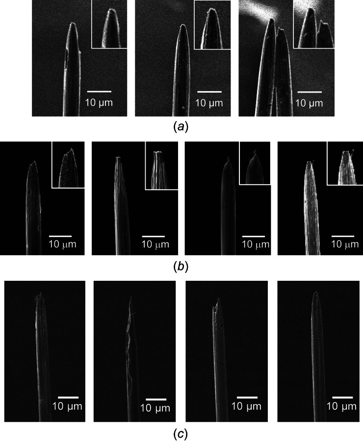
Four tips from (a) 5, (b) 4, and (c) 2.5 DCV input. Serrated asymmetric profiles were observed.
Fig. 10.
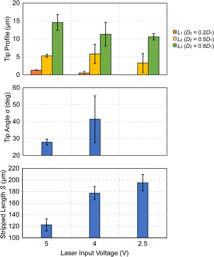
Tip geometry under three laser power levels: tip profile L1, L2, L3, tip angle α and stripped length S
Laser heating increased the temperature in carbon fibers, and the material removal was a result of carbon oxidation to carbon dioxide gas on the fiber surface at temperature above 500 °C [26]. When the laser moved across and temperature dropped below 500 °C, the material removal stopped. The carbon fiber had a large surface to volume ratio and low thermal conductivity of 14 W/(m·K) [19]. Under laser heating, the carbon material near the laser focal point had higher heat flux and resulted in higher temperature and oxidation rate. The oxidation generated a reduced diameter section on the fiber (as shown in Fig. 4(b)). This section had larger specific surface area (inversely proportional to the diameter) compared to regions away from the laser cutting path, leading to larger contact area between carbon material, and oxygen in the air. The larger specific surface area and more heat flux from laser per unit volume further expedited the oxidation and material removal rate for carbon material near the forming tip and progressively generated a conical sharp tip geometry.
At a high laser input voltage and cutting speed, a shorter heat exposure time decreased the amount of heat conducted to the carbon fiber and created an uneven amount of carbon oxidation along the radial direction, leading to less material removal, and longer and shaper tip. In contrast, at lower laser input voltage and slower speed, less heat was conducted along the radial and axial directions of the carbon fiber, causing a less axisymmetric carbon oxidation over longer chemical reaction time, and resulting less sharp tip at 4.0 DCV and 20 μm/s and nonconical shape at 2.5 DCV and 1 μm/s).
The variation in tip angle and profile of four carbon fibers under the same input voltage was mainly due to the difference in the z-direction height of carbon fibers in the MEA assembly. The laser beam intensity will be higher at the center of laser focal spot. Therefore, the temperature in the carbon fiber would be higher at positions near the focal spot center, resulting in a faster oxidation rate [26] and a sharper carbon fiber tip. It was also observed that higher laser input voltage cutting at high speed leads to less deviations in tip geometry, yielding the standard deviation of 0.1 μm in L1, 0.4 μm in L2, 2.2 μm in L3, and 1.7 deg in α when cutting with 5.0 DCV at 25 μm/s. The standard deviation increased to 0.5 μm, 2.7 μm, 3.3 μm, and 13.8 deg for L1, L2, L3, and α, respectively, during the laser cutting and sharpening of carbon fiber with decreased 4.0 DCV input and 20 μm/s speed.
3.3 Experiment II: Stripped Length of Parylene-C Insulation.
Results of the stripped length S at the maximum cutting speed under different laser input voltage levels are shown in Table 1 and Fig. 10. The highest laser power 1.5 W resulted in the shortest average stripped length of 122.5 μm. The stripped length increased as the laser power (or input voltage) decreased. As the speed decreased, the laser heated the carbon fiber for a longer time. The temperature of a larger surface area on the carbon fiber reached the parylene-C melting point, resulting in a longer stripped length. The standard deviation in stripped length also increased from 10.4 μm to 14.1 μm as the laser input voltage decreased from 5 to 2.5 DCV.
In brain recording, a sharp tip with short stripped length (small surface area of recording site) is preferred for a low insertion force [31,32] and accurate recording of single neuron activities [13,28]. Sharpening with high laser power at the maximum allowable speed is preferred. Also, a short laser-carbon fiber interaction duration reduces the variation in sharpness caused by variation of carbon fiber z-direction height.
3.4 Experiment II: Impedance of Laser Sharpened Carbon Fiber in Microelectrode Array.
Impedance of parylene-C-coated carbon fibers after laser sharpening and insulation removal was evaluated as a functionality test. Carbon fiber electrodes sharpened with laser beam (1.5 W power and 25 μm/s speed) have an average 1 kHz impedance of 460±225 kΩ (mean±standard deviation), which is significantly lower than that of traditional steel scissor cut carbon fibers (6.7±3.3 MΩ) [28] or torch burning carbon fibers (1.2±1.3 MΩ [13]). While low impedance of the laser sharpened carbon fibers was partially due to the larger exposed area (2433 μm2), compared to that of 629 μm2 for torch burning. The laser sharpening of carbon fiber electrodes is a highly controllable method and could be further investigated to optimize the balance between insulation stripping and impedance.
3.5 Experiment III: Fabrication of an Array With Custom Electrode Lengths.
As described in Fig. 7(b), the fabrication of an array with different carbon fiber lengths using Path II was conducted under 1.5 W laser power at 25 μm/s speed. As shown in Fig. 11(a), the laser moved along a staircase path from left to right. The carbon fiber array with defined electrode lengths was fabricated in one-pass of laser cutting. As shown in the SEM image (Fig. 11(b)), the array has custom electrode lengths and exposed carbon fiber tips.
Fig. 11.
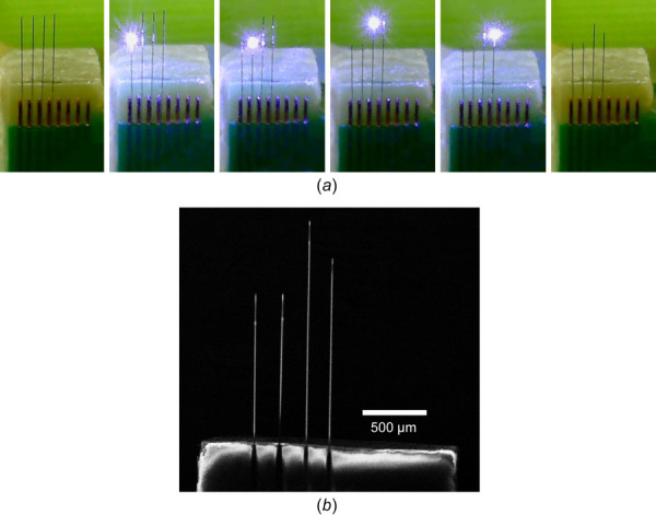
Experiment III results: (a) snapshots of ongoing cutting and sharpening process to get an array of carbon fiber in different lengths (with l1 = 1.2 mm, l2 = 1.2 mm, l3 = 1.6 mm, and l4 = 1.4 mm in Fig. 6) and (b) SEM image of the array
4 Conclusions and Future Work
A new sharpening method for carbon fiber MEAs for brain recording based on a moving laser beam was developed and tested. Results showed that the newly developed method enabled efficient sharpening of a carbon fiber MEA with custom electrode length. To achieve a sharper tip with minimal insulation layer stripped, a high-power laser at maximum allowable speed is preferred. This research overcomes a key barrier in manufacturing preassembled carbon fiber MEAs by using the laser for noncontact sharpening with repeatable shape. To further reduce the stripped length from 120 to 150 μm in this study to an ideal value of less than 50 μm for accurate single neuron activity recording with proper impedance, further study is focused on laser cutting and sharpening with barely minimum thermal energy. Future work also includes more comprehensive design of experiment with one-factor-at-a-time method, the study of material removal mechanism during the laser sharpening process and quantitative prediction of the stripped length and sharpened tip geometry.
Acknowledgment
The authors would like to thank Drs. Cindy Chestek and Paras Patel and Ms. Julianna Richie of the University of Michigan's Cortical Neural Prosthetics Lab for their assistance in the assembly of carbon fiber MEAs and impedance tests. Supports from Nation Institute of Health (NIH) National Institute of Neurological Disorders and Stroke (NINDS) grant UF1NS107659 and University of Michigan MCUBED 3.0 are acknowledged.
Funding Data
National Institutes of Health (Grant No. UF1NS107659; Funder ID: 10.13039/100000002).
University of Michigan (Grant No. MCUBED 3.0; Funder ID: 10.13039/100007270).
Nomenclature
- D1 =
carbon fiber diameter (without parylene-C coating) before cutting, μm
- D2 =
carbon fiber diameter after cutting, μm
- l1, l2, l3, l4 =
carbon fiber electrode lengths, mm
- L1, L2, L3 =
carbon fiber tip profile, μm
- S =
carbon fiber stripped length, μm
- α =
carbon fiber tip angle, deg
References
- [1]. Drachman, D. A. , 2005, “ Do We Have Brain to Spare?,” Neurology, 64(12), pp. 2004–2005. 10.1212/01.WNL.0000166914.38327.BB [DOI] [PubMed] [Google Scholar]
- [2]. Henze, D. A. , Borhegyi, Z. , Csicsvari, J. , Mamiya, A. , Harris, K. D. , and Buzsáki, G. , 2000, “ Intracellular Features Predicted by Extracellular Recordings in the Hippocampus In Vivo,” J. Neurophysiol., 84(1), pp. 390–400. 10.1152/jn.2000.84.1.390 [DOI] [PubMed] [Google Scholar]
- [3]. Burle, B. , Spieser, L. , Roger, C. , Casini, L. , Hasbroucq, T. , and Vidal, F. , 2015, “ Spatial and Temporal Resolutions of EEG: Is It Really Black and White? A Scalp Current Density View,” Int. J. Psychophysiol., 97(3), pp. 210–220. 10.1016/j.ijpsycho.2015.05.004 [DOI] [PMC free article] [PubMed] [Google Scholar]
- [4]. Dale, A. M. , Liu, A. K. , Fischl, B. R. , Buckner, R. L. , Belliveau, J. W. , Lewine, J. D. , and Halgren, E. , 2000, “ Dynamic Statistical Parametric Mapping: Combining FMRI and MEG for High-Resolution Imaging of Cortical Activity,” Neuron, 26(1), pp. 55–67. 10.1016/S0896-6273(00)81138-1 [DOI] [PubMed] [Google Scholar]
- [5]. Drake, K. L. , Wise, K. D. , Farraye, J. , Anderson, D. J. , and BeMent, S. L. , 1988, “ Performance of Planar Multisite Microprobes in Recording Extracellular Single-Unit Intracortical Activity,” IEEE Trans. Biomed. Eng., 35(9), pp. 719–732. 10.1109/10.7273 [DOI] [PubMed] [Google Scholar]
- [6]. Campbell, P. K. , Jones, K. E. , Huber, R. J. , Horch, K. W. , and Normann, R. A. , 1991, “ A Silicon-Based, Three-Dimensional Neural Interface: Manufacturing Processes for an Intracortical Electrode Array,” IEEE Trans. Biomed. Eng., 38(8), pp. 758–768. 10.1109/10.83588 [DOI] [PubMed] [Google Scholar]
- [7]. Polikov, V. S. , Tresco, P. A. , and Reichert, W. M. , 2005, “ Response of Brain Tissue to Chronically Implanted Neural Electrodes,” J. Neurosci. Methods, 148(1), pp. 1–18. 10.1016/j.jneumeth.2005.08.015 [DOI] [PubMed] [Google Scholar]
- [8]. Karumbaiah, L. , Saxena, T. , Carlson, D. , Patil, K. , Patkar, R. , Gaupp, E. A. , Betancur, M. , Stanley, G. B. , Carin, L. , and Bellamkonda, R. V. , 2013, “ Relationship Between Intracortical Electrode Design and Chronic Recording Function,” Biomaterials, 34(33), pp. 8061–8074. 10.1016/j.biomaterials.2013.07.016 [DOI] [PubMed] [Google Scholar]
- [9]. Chung, J. E. , Joo, H. R. , Fan, J. L. , Liu, D. F. , Barnett, A. H. , Chen, S. , Geaghan-Breiner, C. , Karlsson, M. P. , Karlsson, M. , Lee, K. Y. , Liang, H. , Magland, J. F. , Pebbles, J. A. , Tooker, A. C. , Greengard, L. F. , Tolosa, V. M. , and Frank, L. M. , 2019, “ High-Density, Long-Lasting, and Multi-Region Electrophysiological Recordings Using Polymer Electrode Arrays,” Neuron, 101(1), pp. 21–31.e5. 10.1016/j.neuron.2018.11.002 [DOI] [PMC free article] [PubMed] [Google Scholar]
- [10]. Musk, E. , Neuralink, 2019, “ An Integrated Brain-Machine Interface Platform With Thousands of Channels,” J. Med. Internet Res., 21(10), p. e16194. 10.2196/16194 [DOI] [PMC free article] [PubMed] [Google Scholar]
- [11]. Patel, P. R. , Na, K. , Zhang, H. , Kozai, T. D. Y. , Kotov, N. A. , Yoon, E. , and Chestek, C. A. , 2015, “ Insertion of Linear 8.4 Μm Diameter 16 Channel Carbon Fiber Electrode Arrays for Single Unit Recordings,” J. Neural Eng., 12(4), p. 046009. 10.1088/1741-2560/12/4/046009 [DOI] [PMC free article] [PubMed] [Google Scholar]
- [12]. Patel, P. R. , 2015, “ Carbon FIiber Microelectrode Arrays for Neuroprosthetic and Neuroscience Applications,” Ph.D. thesis, University of Michigan, Ann Arbor, MI. [Google Scholar]
- [13]. Guitchounts, G. , Markowitz, J. E. , Liberti, W. A. , and Gardner, T. J. , 2013, “ A Carbon-Fiber Electrode Array for Long-Term Neural Recording,” J. Neural Eng., 10(4), p. 046016. 10.1088/1741-2560/10/4/046016 [DOI] [PMC free article] [PubMed] [Google Scholar]
- [14]. Patel, P. R. , Zhang, H. , Robbins, M. T. , Nofar, J. B. , Marshall, S. P. , Kobylarek, M. J. , Kozai, T. D. Y. , Kotov, N. A. , and Chestek, C. A. , 2016, “ Chronic In Vivo Stability Assessment of Carbon Fiber Microelectrode Arrays,” J. Neural Eng., 13(6), p. 066002. 10.1088/1741-2560/13/6/066002 [DOI] [PMC free article] [PubMed] [Google Scholar]
- [15]. Rose, J. D. , and Weishaar, D. J. , 1979, “ Tapered Tungsten Fine-Wire Microelectrode for Chronic Single Unit Recording,” Brain Res. Bull., 4(3), pp. 435–437. 10.1016/S0361-9230(79)80022-2 [DOI] [PubMed] [Google Scholar]
- [16]. Xie, K. , Fox, G. E. , Liu, J. , and Tsien, J. Z. , 2016, “ 512-Channel and 13-Region Simultaneous Recordings Coupled With Optogenetic Manipulation in Freely Behaving Mice,” Front. Syst. Neurosci., 10, p. 48. 10.3389/fnsys.2016.00048A [DOI] [PMC free article] [PubMed] [Google Scholar]
- [17]. Schwarz, D. A. , Lebedev, M. A. , Hanson, T. L. , Dimitrov, D. F. , Lehew, G. , Meloy, J. , Rajangam, S. , Subramanian, V. , Ifft, P. J. , Li, Z. , Ramakrishnan, A. , Tate, A. , Zhuang, K. Z. , and Nicolelis, M. A. L. , 2014, “ Chronic, Wireless Recordings of Large-Scale Brain Activity in Freely Moving Rhesus Monkeys,” Nat. Methods, 11(6), pp. 670–676. 10.1038/nmeth.2936 [DOI] [PMC free article] [PubMed] [Google Scholar]
- [18]. Liao, Y. F. , Tsai, M. L. , Yen, C. T. , and Cheng, C. H. , 2011, “ A Simple Method for Fabricating Microwire Tetrode With Sufficient Rigidity and Integrity Without a Heat-Fusing Process,” J. Neurosci. Methods, 195(2), pp. 211–215. 10.1016/j.jneumeth.2010.12.017 [DOI] [PubMed] [Google Scholar]
- [19].MatWeb, 2012, “ Solvay Thornel® T-650/35 3K Carbon Fiber, Polyacrylonitrile (PAN) Precursor,” MatWeb, LLC, Blacksburg, VA, accessed Jan. 1, 2019, http://www.matweb.com/search/datasheet.aspx?matguid=7e9aca60a2e84538a4 e8038784f2b629&ckck=1
- [20]. Ledbetter, H. M. , Frederick, N. V. , and Austin, M. W. , 1980, “ Elastic-Constant Variability in Stainless-Steel 304 Articles You May Be Interested In,” J. Appl. Phys., 51(1), pp. 305–309. 10.1063/1.327371 [DOI] [Google Scholar]
- [21]. Farraro, R. , and McLellan, R. B. , 1977, “ Temperature Dependence of the Young'S Modulus and Shear Modulus of Pure Nickel, Platinum, and Molybdenum,” Met. Trans A, 8(10), pp. 1563–1565. 10.1007/BF02644859 [DOI] [Google Scholar]
- [22]. Budai, D. , 2010, Carbon Fiber-Based Microelectrodes and Microbiosensors, Intelligent and Biosensors, Intech Open, Rijeka, Croatia, pp. 269–288. [Google Scholar]
- [23]. Massey, T. L. , Santacruz, S. R. , Hou, J. F. , Pister, K. S. J. , Carmena, J. M. , and Maharbiz, M. M. , 2019, “ A High-Density Carbon Fiber Neural Recording Array Technology,” J. Neural Eng., 16(1), p. 016024. 10.1088/1741-2552/aae8d9 [DOI] [PubMed] [Google Scholar]
- [24]. Xu, H. , Hsiao, M. C. , Song, D. , and Berger, T. W. , 2014, “ Recording Place Cells From Multiple Sub-Regions of the Rat Hippocampus With a Customized Micro-Electrode Array,” 36th Annual International Conference of the IEEE Engineering in Medicine and Biology Society (EMBC 2014), Institute of Electrical and Electronics Engineers, Chicago, IL, Aug. 26–30, pp. 4876–4879. 10.1109/EMBC.2014.6944716 [DOI] [PubMed] [Google Scholar]
- [25]. Millar, J. , and Pelling, C. W. A. , 2001, “ Improved Methods for Construction of Carbon Fibre Electrodes for Extracellular Spike Recording,” J. Neurosci. Methods, 110(1–2), pp. 1–8. 10.1016/S0165-0270(01)00411-3 [DOI] [PubMed] [Google Scholar]
- [26]. Yin, Y. , Binner, J. G. P. , Cross, T. E. , and Marshall, S. J. , 1994, “ The Oxidation Behaviour of Carbon Fibres,” J. Mater. Sci., 29(8), pp. 2250–2254. 10.1007/BF01154706 [DOI] [Google Scholar]
- [27]. Von Metzen, R. P. , and Stieglitz, T. , 2013, “ The Effects of Annealing on Mechanical, Chemical, and Physical Properties and Structural Stability of Parylene C,” Biomed. Microdev., 15(5), pp. 727–735. 10.1007/s10544-013-9758-8 [DOI] [PubMed] [Google Scholar]
- [28]. Welle, E. J. , Patel, P. R. , Woods, J. E. , Petrossians, A. , Della Valle, E. , Vega-Medina, A. , Richie, J. M. , Cai, D. , Weiland, J. D. , and Chestek, C. A. , 2020, “ Ultra-Small Carbon Fiber Electrode Recording Site Optimization and Improved In Vivo Chronic Recording Yield,” J. Neural Eng., 17(2), p. 026037. 10.1088/1741-2552/ab8343 [DOI] [PMC free article] [PubMed] [Google Scholar]
- [29]. Schindelin, J. , Arganda-Carreras, I. , Frise, E. , Kaynig, V. , Longair, M. , Pietzsch, T. , Preibisch, S. , Rueden, C. , Saalfeld, S. , Schmid, B. , Tinevez, J. Y. , White, D. J. , Hartenstein, V. , Eliceiri, K. , Tomancak, P. , and Cardona, A. , 2012, “ Fiji: An Open-Source Platform for Biological-Image Analysis,” Nat. Methods, 9(7), pp. 676–682. 10.1038/nmeth.2019 [DOI] [PMC free article] [PubMed] [Google Scholar]
- [30]. Schneider, C. A. , Rasband, W. S. , and Eliceiri, K. W. , 2012, “ NIH Image to ImageJ: 25 Years of Image Analysis,” Nat. Methods, 9(7), pp. 671–675. 10.1038/nmeth.2089 [DOI] [PMC free article] [PubMed] [Google Scholar]
- [31]. Sharp, A. A. , Ortega, A. M. , Restrepo, D. , Curran-Everett, D. , and Gall, K. , 2009, “ In Vivo Penetration Mechanics and Mechanical Properties of Mouse Brain Tissue at Micrometer Scales,” IEEE Trans. Biomed. Eng., 56(1), pp. 45–53. 10.1109/TBME.2008.2003261 [DOI] [PMC free article] [PubMed] [Google Scholar]
- [32]. Chen, L. , Hartner, J. P. , Dong, T. , Li, A. D. R. , Watson, B. O. , and Shih, A. J. , “ Flexible High-Resolution Force and Dimpling Measurement for Pia and Dura Penetration During In-Vivo Microelectrode Insertion Into Rat Brain,” IEEE Trans. Biomed. Eng. (submitted). [DOI] [PMC free article] [PubMed] [Google Scholar]
- [33].Budai, D. , and Molnár, Z. , 2001, “ Novel Carbon Fiber Microeletrodes for Extracellular Electrophysiology,” Acta Biologica Szegediensis, 45(1–4), pp. 65–73. [Google Scholar]